EP0905305A1 - Stahlseil zur Verstärkung von Gummiartikeln und solche Stahlseile aufweisender Luftreifen - Google Patents
Stahlseil zur Verstärkung von Gummiartikeln und solche Stahlseile aufweisender Luftreifen Download PDFInfo
- Publication number
- EP0905305A1 EP0905305A1 EP97307057A EP97307057A EP0905305A1 EP 0905305 A1 EP0905305 A1 EP 0905305A1 EP 97307057 A EP97307057 A EP 97307057A EP 97307057 A EP97307057 A EP 97307057A EP 0905305 A1 EP0905305 A1 EP 0905305A1
- Authority
- EP
- European Patent Office
- Prior art keywords
- steel
- core
- steel cord
- reinforcing
- rubber product
- Prior art date
- Legal status (The legal status is an assumption and is not a legal conclusion. Google has not performed a legal analysis and makes no representation as to the accuracy of the status listed.)
- Withdrawn
Links
- 229910000831 Steel Inorganic materials 0.000 title claims abstract description 81
- 239000010959 steel Substances 0.000 title claims abstract description 81
- 230000003014 reinforcing effect Effects 0.000 title claims abstract description 21
- 238000005452 bending Methods 0.000 claims abstract description 8
- 239000011324 bead Substances 0.000 claims abstract description 4
- 230000000052 comparative effect Effects 0.000 description 22
- 239000011295 pitch Substances 0.000 description 18
- 230000035515 penetration Effects 0.000 description 9
- 238000004519 manufacturing process Methods 0.000 description 5
- 230000000694 effects Effects 0.000 description 3
- 238000000926 separation method Methods 0.000 description 3
- 230000006835 compression Effects 0.000 description 2
- 238000007906 compression Methods 0.000 description 2
- 239000013013 elastic material Substances 0.000 description 2
- 238000011156 evaluation Methods 0.000 description 2
- 230000005540 biological transmission Effects 0.000 description 1
- 230000015556 catabolic process Effects 0.000 description 1
- 238000005260 corrosion Methods 0.000 description 1
- 230000007797 corrosion Effects 0.000 description 1
- 238000006731 degradation reaction Methods 0.000 description 1
- 238000002360 preparation method Methods 0.000 description 1
- 230000003252 repetitive effect Effects 0.000 description 1
- 238000005096 rolling process Methods 0.000 description 1
Images


Classifications
-
- D—TEXTILES; PAPER
- D07—ROPES; CABLES OTHER THAN ELECTRIC
- D07B—ROPES OR CABLES IN GENERAL
- D07B7/00—Details of, or auxiliary devices incorporated in, rope- or cable-making machines; Auxiliary apparatus associated with such machines
- D07B7/02—Machine details; Auxiliary devices
- D07B7/025—Preforming the wires or strands prior to closing
-
- B—PERFORMING OPERATIONS; TRANSPORTING
- B60—VEHICLES IN GENERAL
- B60C—VEHICLE TYRES; TYRE INFLATION; TYRE CHANGING; CONNECTING VALVES TO INFLATABLE ELASTIC BODIES IN GENERAL; DEVICES OR ARRANGEMENTS RELATED TO TYRES
- B60C9/00—Reinforcements or ply arrangement of pneumatic tyres
- B60C9/0057—Reinforcements comprising preshaped elements, e.g. undulated or zig-zag filaments
-
- D—TEXTILES; PAPER
- D07—ROPES; CABLES OTHER THAN ELECTRIC
- D07B—ROPES OR CABLES IN GENERAL
- D07B1/00—Constructional features of ropes or cables
- D07B1/06—Ropes or cables built-up from metal wires, e.g. of section wires around a hemp core
- D07B1/0606—Reinforcing cords for rubber or plastic articles
- D07B1/062—Reinforcing cords for rubber or plastic articles the reinforcing cords being characterised by the strand configuration
- D07B1/064—Reinforcing cords for rubber or plastic articles the reinforcing cords being characterised by the strand configuration the reinforcing cords being twisted and with at least one wire exchanging place with another wire
-
- D—TEXTILES; PAPER
- D07—ROPES; CABLES OTHER THAN ELECTRIC
- D07B—ROPES OR CABLES IN GENERAL
- D07B1/00—Constructional features of ropes or cables
- D07B1/06—Ropes or cables built-up from metal wires, e.g. of section wires around a hemp core
- D07B1/0606—Reinforcing cords for rubber or plastic articles
- D07B1/0646—Reinforcing cords for rubber or plastic articles comprising longitudinally preformed wires
- D07B1/0653—Reinforcing cords for rubber or plastic articles comprising longitudinally preformed wires in the core
-
- D—TEXTILES; PAPER
- D07—ROPES; CABLES OTHER THAN ELECTRIC
- D07B—ROPES OR CABLES IN GENERAL
- D07B2201/00—Ropes or cables
- D07B2201/20—Rope or cable components
- D07B2201/2001—Wires or filaments
- D07B2201/2007—Wires or filaments characterised by their longitudinal shape
- D07B2201/2008—Wires or filaments characterised by their longitudinal shape wavy or undulated
-
- D—TEXTILES; PAPER
- D07—ROPES; CABLES OTHER THAN ELECTRIC
- D07B—ROPES OR CABLES IN GENERAL
- D07B2201/00—Ropes or cables
- D07B2201/20—Rope or cable components
- D07B2201/2015—Strands
- D07B2201/2022—Strands coreless
-
- D—TEXTILES; PAPER
- D07—ROPES; CABLES OTHER THAN ELECTRIC
- D07B—ROPES OR CABLES IN GENERAL
- D07B2201/00—Ropes or cables
- D07B2201/20—Rope or cable components
- D07B2201/2015—Strands
- D07B2201/2023—Strands with core
-
- D—TEXTILES; PAPER
- D07—ROPES; CABLES OTHER THAN ELECTRIC
- D07B—ROPES OR CABLES IN GENERAL
- D07B2201/00—Ropes or cables
- D07B2201/20—Rope or cable components
- D07B2201/2015—Strands
- D07B2201/2024—Strands twisted
-
- D—TEXTILES; PAPER
- D07—ROPES; CABLES OTHER THAN ELECTRIC
- D07B—ROPES OR CABLES IN GENERAL
- D07B2201/00—Ropes or cables
- D07B2201/20—Rope or cable components
- D07B2201/2015—Strands
- D07B2201/2036—Strands characterised by the use of different wires or filaments
-
- D—TEXTILES; PAPER
- D07—ROPES; CABLES OTHER THAN ELECTRIC
- D07B—ROPES OR CABLES IN GENERAL
- D07B2501/00—Application field
- D07B2501/20—Application field related to ropes or cables
- D07B2501/2046—Tire cords
-
- Y—GENERAL TAGGING OF NEW TECHNOLOGICAL DEVELOPMENTS; GENERAL TAGGING OF CROSS-SECTIONAL TECHNOLOGIES SPANNING OVER SEVERAL SECTIONS OF THE IPC; TECHNICAL SUBJECTS COVERED BY FORMER USPC CROSS-REFERENCE ART COLLECTIONS [XRACs] AND DIGESTS
- Y10—TECHNICAL SUBJECTS COVERED BY FORMER USPC
- Y10S—TECHNICAL SUBJECTS COVERED BY FORMER USPC CROSS-REFERENCE ART COLLECTIONS [XRACs] AND DIGESTS
- Y10S57/00—Textiles: spinning, twisting, and twining
- Y10S57/902—Reinforcing or tire cords
Definitions
- the present invention relates to a steel cord for reinforcing a rubber product, having good penetration of rubber and high rigidity, and to a pneumatic tire having improved durability, steering stability and uniformity through the use of this steel cord as a reinforcing member.
- steel cords into which an elastic material such as rubber can penetrate have been proposed in order to improve the durability of rubber products reinforced by the steel cords.
- an open cord 100 which is composed of filaments 102 twisted together in large spirals with gaps 104 therebetween in order to permit penetration of rubber into the cord 100.
- the open cord 100 has drawbacks caused by its low rigidity due to the filaments 102 being twisted together in large spirals. For example, it is difficult to maintain good uniformity of tires when the open cord 100 is used, because the open cord 100 can easily elongate under a low tensile load such as that applied to the cord in the production process of tires.
- a steel cord which comprises at least one filament having a spiral shape prior to twisting with other filaments and in which these filaments are twisted together such that the twisting pitch of the steel cord is larger than the spiral pitch of said at least one filaments, is disclosed in Japanese Utility Model Application Laid-Open (JP-U) No. 4-60589.
- JP-U Japanese Utility Model Application Laid-Open
- a 1+3 structure in which the core filament 114 has a continuous wave shape (Fig. 6) is disclosed in Japanese Patent Application Laid-Open (JP-A) No. 5-295682.
- the present invention has been made in light of the above circumstances, and an object thereof is to provide a steel cord for reinforcing a rubber product having higher rigidity and more reliable penetration of an elastic material such as rubber.
- Another object is to provide a pneumatic tire with improved durability, steering stability and uniformity.
- a steel cord for reinforcing a rubber product according to the present invention comprises a core consisting of one steel filament and a sheath consisting of a plurality of steel filaments wound around the core, with the steel filament forming the core alternately having straight portions, whose axes are disposed on one line, and protrusions formed by bending.
- a pneumatic tire according to the present invention comprises a carcass having a toroidal shape extending over a pair of beads, and at least one belt layer reinforcing the crown portion of the carcass, and the above-described steel cord for reinforcing a rubber product is used in at least one of the carcass and the belt layer.
- the feature of the steel cord of the present invention is the shape of the filament forming the core (hereinafter called "core filament"), that is, the core filament should alternately have straight portions, whose axes are disposed on one (a single) line, and protrusions formed by bending.
- the protrusions of the core filament prevent the filaments forming the sheath (hereinafter called “sheath filaments) from contacting each other due to the tension or compression which arises in the production process of rubber products such as tires, and thus, penetration of rubber is ensured.
- steel cord of the present invention exhibits high rigidity and low elongation when a tensile load is applied thereto.
- the steel cord of the present invention can provide superior durability, steering stability and uniformity for a tire using the steel cord.
- Fig 2 shows a steel cord 10 of the present invention.
- the steel cord 10 comprises a core filament 12 and a sheath 14.
- the sheath 14 is comprised of three sheath filaments 14A, 14B and 14C.
- the diameter, d, of the core filament 12 is the same as the diameter, D, of each sheath filament 14A, 14B or 14C.
- Fig. 1 shows the core filament 12.
- the core filament 12 alternately has straight portions 16, whose axes are disposed on one line, and protrusions 18 formed by bending.
- the length of each straight portion 16 is the same and the length of each protrusion 18 is the same in the longitudinal direction of the core filament 12.
- the adjacent protrusions 18 are formed so that the direction of the tops of these protrusions 18 are opposite to each other.
- Each of the protrusions 18 has the same height, which is a height sufficient to allow each protrusion 18 to be interposed between any two of the sheath filaments 14A, 14B and 14C.
- the sheath filaments 14A, 14B and 14C are wound around the core filament 12 so that the twisting pitch of the sheath filaments 14A, 14B and 14C is substantially the same as the length between adjacent protrusions 18 which are disposed on the same side of the core filament 12, as shown in Fig. 2.
- the steel cord 10 satisfies the following formulas (1) to (3). 0.1D ⁇ H ⁇ D 0.14P ⁇ L ⁇ 0.2P 0.95P ⁇ C ⁇ 1.05P
- H is the height of each protrusion 18 in the direction perpendicular to the longitudinal direction of the core filament 12 and L is the length of each protrusion 18 in the longitudinal direction of the core filament 12, and P is the twisting pitch of the sheath 14, and C is the distance between adjacent protrusions 18 which are disposed on the same side of the core filament 12.
- the effect of reducing elongation under tensile load also deteriorates when the distance C between adjacent protrusions 18 which are disposed on the same side of the core filament 12 is shortened.
- the distance C is too large, the tensile stress generated in the core filament 12 by tensile load applied to the steel cord 10 exceeds the tensile stress in the sheath filaments 14A, 14B and 14C. This may cause earlier breakage of the core filament 12 under repetitive load, such as a load which is generated in a rolling tire, resulting in undesirable degradation of fatigue resistance of a rubber product reinforced by the steel cord 10. Therefore, it is preferable that distance C is almost same as the twisting pitch P and satisfies 0.95P ⁇ C ⁇ 1.05P.
- the length of each straight portion 16 is more than 30% of the twisting pitch P of the sheath 14.
- each straight portion 16 can have a different length.
- each protrusion 18 can have a different length and a different height.
- each filament that is, the core filament 12 or the sheath filament 14A, 14B or 14C
- each filament can have a different diameter.
- the number of sheath filaments is preferably 2 to 4 in order to maintain gaps between adjacent filaments even when all of the sheath filaments come into contact with the core filament.
- the protrusions 18 may be formed on the same side or on all sides of the core filament 12. However, it is preferable that adjacent protrusions 18 are formed on opposite sides of the core filament 12, because it is easy to produce such a core filament and it is undesirable for open gaps to collect on only one side of the core filament 12.
- each protrusion 18 shown in Fig. 1 is formed by angular bending portions
- the protrusions used in the present invention can be any shape provided that the protrusions can be interposed between the sheath filaments 14A, 14B and 14C. Therefore, protrusions formed by curved bending portions can be used in the present invention.
- a forming device 26 shown in Fig. 3 can be used for the production of the core filament 12.
- the forming device 26 includes a pair of forming rollers 24 on the periphery of which concave portions 20 and convex portions 22 are provided.
- the core filament 12 can be prepared by supplying a filament from a bobbin of a twisting machine (not shown) to the pair of forming rollers 24, and passing the filament between the pair of forming rollers 24 to bend it by the engagement of concave portion 20 and convex portion 22, as shown in Fig. 3, for the preparation of the protrusions 18.
- the sheath filaments 14A, 14B and 14C will be wound around the core filament 12 thus obtained to form the steel cord 10.
- the steel cord 10 can be used in parts of tires, such as a carcass, a belt layer and the like.
- each steel cord shown in Table 1 was composed of four filaments each having a diameter of 0.26 mm. Moreover, the steel cords in Table 1 had the same twisting pitch of 12.0 mm.
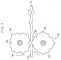
- Comparative Example 1 had a 1 ⁇ 4 open structure having open gaps between adjacent sheath filaments as shown in Fig. 5.
- Comparative Example 2 had a conventional 1 ⁇ 4 closed structure having no open gaps between adjacent sheath filaments as shown in Fig. 7. Further, Comparative Example 3 had a 1+3 structure with the core filament having a continuous wave form as shown in Fig. 6.
- Examples 1 to 4 were steel cords according to the present invention (Fig. 2) and had a core filament alternately having straight portions, whose axes were disposed on one line, and protrusions formed by bending as shown in Fig. 1.
- the adjacent protrusions were disposed on opposite sides of the core filament, the length of each straight portion was the same, the length of each protrusion was the same, and the height of each protrusion was the same.
- the length L of each protrusion and the distance C between the adjacent protrusions which were disposed on the same side of the core filament were within the respective preferred ranges, but the height H of each protrusion was larger than the upper limit of the preferred range of H.
- Example 2 the height H and the distance C were within the respective preferred ranges, but were the smallest among Examples 1 to 4. In addition, the length L fell outside of the preferred range of L in Example 2. In Example 3, the height H and the length L were within the respective preferred ranges, but the distance C was longer than the upper limit of the preferred range of C and about twice as long as the length of the twisting pitch of the sheath. Example 4 satisfied the above three conditions.
- Tires (tire size: 205/R15) of the present invention were prepared. As shown in Fig. 4, each tire 28 comprised a carcass 32 having a toroidal shape extending over a pair of beads 34, and two belt layers 30 reinforcing the crown portion of the carcass 32, and one type of the above steel cords was used in the belt layers 30.
- the belt layers 30 comprised a plurality of steel cords which were parallel to each other. The steel cords of each of the belt layers 30 were set at an angle of 20 degrees with respect to the equatorial plane of the tire 28. Further, the two belt layers 30 were disposed so that the axes of the steel cords of one of the belt layers 30 intersected the axes of the steel cords of the other belt layer 30.
- Test items are as follows:
- the first set of five pitches were the first through fifth pitches of the steel cord
- the second set was the second through sixth pitches
- the last set of five pitches was the pitches X-4, X-3, X-2, X-1, X, wherein X represent the final twisting pitch of the steel cord.
- the steel cord was given the evaluation mark B if there were one or more cross-sectional areas with full penetration of rubber in each set of five twisting pitches.
- the steel cord was given the evaluation mark C if there was at least one set of five twisting pitches in which there were no cross-sectional areas at which rubber penetrated all the gaps. The result "B" is acceptable in practical use.
- a belt layer was sampled from each tire and the arrangements of the steel cords in the belt layer were evaluated by observing an X-ray transmission image.
- Comparative Example 3 with a 1+3 structure and a core filament having a continuous wave form, the result was better than that of Comparative 1 and expressed by "B".
- the two results were used as criteria and, as for other samples, if the result was similar to that of Comparative Example 1 or 3, it is expressed by "C” or "B” and if the result was better than that of Comparative Example 3, it is expressed by "A”.
- Examples 1 to 4 show good penetration of rubber, and the tires using these steel cords shows good resistance to separation caused by cut of the tread, which was not achieved by Comparative Example 2.
- the diameters of the steel cords of Examples 1 to 4 were much smaller than that of Comparative Example 3 which showed reasonable results for all the parameters evaluated except for P.L.E.
- the thickness of the belt layer comprising the steel cords of any type of Comparative Examples 1 to 4 were thinner than that comprising the steel cord of Comparative Example 3, resulting in lighter tires.
- Example 4 which satisfied all the preferred conditions showed the best compatibility for parameters evaluated.
Priority Applications (2)
| Application Number | Priority Date | Filing Date | Title |
|---|---|---|---|
| EP97307057A EP0905305A1 (de) | 1997-09-11 | 1997-09-11 | Stahlseil zur Verstärkung von Gummiartikeln und solche Stahlseile aufweisender Luftreifen |
| US08/956,706 US5911675A (en) | 1997-09-11 | 1997-10-23 | Steel cord for reinforcing rubber product and pneumatic tire using such steel cord |
Applications Claiming Priority (2)
| Application Number | Priority Date | Filing Date | Title |
|---|---|---|---|
| EP97307057A EP0905305A1 (de) | 1997-09-11 | 1997-09-11 | Stahlseil zur Verstärkung von Gummiartikeln und solche Stahlseile aufweisender Luftreifen |
| US08/956,706 US5911675A (en) | 1997-09-11 | 1997-10-23 | Steel cord for reinforcing rubber product and pneumatic tire using such steel cord |
Publications (1)
| Publication Number | Publication Date |
|---|---|
| EP0905305A1 true EP0905305A1 (de) | 1999-03-31 |
Family
ID=26147600
Family Applications (1)
| Application Number | Title | Priority Date | Filing Date |
|---|---|---|---|
| EP97307057A Withdrawn EP0905305A1 (de) | 1997-09-11 | 1997-09-11 | Stahlseil zur Verstärkung von Gummiartikeln und solche Stahlseile aufweisender Luftreifen |
Country Status (2)
| Country | Link |
|---|---|
| US (1) | US5911675A (de) |
| EP (1) | EP0905305A1 (de) |
Cited By (1)
| Publication number | Priority date | Publication date | Assignee | Title |
|---|---|---|---|---|
| KR100567812B1 (ko) | 2004-12-31 | 2006-04-05 | 주식회사 효성 | 단선 스틸코드 |
Families Citing this family (7)
| Publication number | Priority date | Publication date | Assignee | Title |
|---|---|---|---|---|
| KR100916917B1 (ko) * | 2007-11-06 | 2009-09-09 | 주식회사 효성 | 단선 스틸코드 |
| JP5623425B2 (ja) * | 2009-01-09 | 2014-11-12 | ナムローゼ・フェンノートシャップ・ベーカート・ソシエテ・アノニムN V Bekaert Societe Anonyme | タイヤ補強用鋼コード |
| CN104338873A (zh) * | 2013-07-29 | 2015-02-11 | 贝卡尔特公司 | 用于带束层上的直的单丝 |
| EP3420137A1 (de) * | 2016-02-23 | 2019-01-02 | NV Bekaert SA | Energieaufnahmeanordnung |
| US10246823B2 (en) * | 2016-07-11 | 2019-04-02 | Hall Labs Llc | Compressible rope |
| DE102016225234A1 (de) * | 2016-11-25 | 2018-05-30 | Continental Reifen Deutschland Gmbh | Fahrzeugluftreifen mit einer Gürtellage aufweisend Stahl-Festigkeitsträger |
| CN112647328A (zh) * | 2020-12-28 | 2021-04-13 | 江苏兴达钢帘线股份有限公司 | 一种钢帘线及其制备工艺 |
Citations (5)
| Publication number | Priority date | Publication date | Assignee | Title |
|---|---|---|---|---|
| US5020312A (en) * | 1989-05-23 | 1991-06-04 | Kokoku Steel Wire Ltd. | Tire steel cords and method of manufacturing thereof |
| EP0462716A1 (de) * | 1990-06-16 | 1991-12-27 | Tokusen Kogyo Company Limited | Stahlkabel zur Verstärkung von elastomeren Erzeugnissen |
| EP0551124A2 (de) * | 1992-01-09 | 1993-07-14 | Bridgestone Corporation | Stahlseil |
| EP0566350A1 (de) * | 1992-04-17 | 1993-10-20 | Bridgestone Corporation | Stahlkabel für Elastomererzeugnisse und radiale Luftreifen mit solchen Kabeln |
| JPH05295682A (ja) * | 1992-04-17 | 1993-11-09 | Bridgestone Corp | エラストマー製品補強用スチールコード |
Family Cites Families (9)
| Publication number | Priority date | Publication date | Assignee | Title |
|---|---|---|---|---|
| USH1333H (en) * | 1990-03-21 | 1994-07-05 | Helfer Farrel B | High strength reinforcement |
| US5337549A (en) * | 1989-12-20 | 1994-08-16 | Tokusen Kogyo Company Limited | Steel cord for reinforcement of rubber products |
| JPH0460589A (ja) * | 1990-06-29 | 1992-02-26 | Hitachi Ltd | 分割スクロール方式 |
| JPH04281081A (ja) * | 1991-03-06 | 1992-10-06 | Bridgestone Corp | ゴム補強用金属コ−ド及びこれを使用したタイヤ |
| JPH05302282A (ja) * | 1992-04-24 | 1993-11-16 | Bridgestone Corp | ゴム物品補強用スチールコード及び重荷重用空気入りラジアルタイヤ |
| JP3222257B2 (ja) * | 1993-04-09 | 2001-10-22 | 株式会社ブリヂストン | ゴム物品補強用スチールコード及びそれを用いた空気入りラジアルタイヤ |
| WO1995016816A1 (en) * | 1993-12-15 | 1995-06-22 | N.V. Bekaert S.A. | Open steel cord structure |
| US5707467A (en) * | 1993-12-27 | 1998-01-13 | Tokyo Rope Manufacturing Co., Ltd. | Steel cords, radial tire reinforced with same, and apparatus for producing same |
| US5661966A (en) * | 1996-06-27 | 1997-09-02 | Tokyo Rope Manufacturing Co. Ltd. | Steel cord for reinforcement of off-road tire, method of manufacturing the same, and off-road tire |
-
1997
- 1997-09-11 EP EP97307057A patent/EP0905305A1/de not_active Withdrawn
- 1997-10-23 US US08/956,706 patent/US5911675A/en not_active Expired - Fee Related
Patent Citations (5)
| Publication number | Priority date | Publication date | Assignee | Title |
|---|---|---|---|---|
| US5020312A (en) * | 1989-05-23 | 1991-06-04 | Kokoku Steel Wire Ltd. | Tire steel cords and method of manufacturing thereof |
| EP0462716A1 (de) * | 1990-06-16 | 1991-12-27 | Tokusen Kogyo Company Limited | Stahlkabel zur Verstärkung von elastomeren Erzeugnissen |
| EP0551124A2 (de) * | 1992-01-09 | 1993-07-14 | Bridgestone Corporation | Stahlseil |
| EP0566350A1 (de) * | 1992-04-17 | 1993-10-20 | Bridgestone Corporation | Stahlkabel für Elastomererzeugnisse und radiale Luftreifen mit solchen Kabeln |
| JPH05295682A (ja) * | 1992-04-17 | 1993-11-09 | Bridgestone Corp | エラストマー製品補強用スチールコード |
Cited By (1)
| Publication number | Priority date | Publication date | Assignee | Title |
|---|---|---|---|---|
| KR100567812B1 (ko) | 2004-12-31 | 2006-04-05 | 주식회사 효성 | 단선 스틸코드 |
Also Published As
| Publication number | Publication date |
|---|---|
| US5911675A (en) | 1999-06-15 |
Similar Documents
| Publication | Publication Date | Title |
|---|---|---|
| US4371025A (en) | Reinforcing annular structure of radial tires | |
| CA1246945A (en) | Reinforcing cord with wrap-around wire | |
| US5858137A (en) | Radial tires having at least two belt plies reinforced with steel monofilaments | |
| US4836262A (en) | Metal cords and pneumatic tires using the same | |
| EP0524702A2 (de) | Radialer Luftreifen | |
| EP0543640B1 (de) | Luftreifen | |
| EP1712376B1 (de) | Luftreifen | |
| EP2065512A1 (de) | Stahlkord, verbund aus gummi und stahlkord sowie reifen | |
| EP2388372B1 (de) | Stahlkord zur armierung eines gummierzeugnisses sowie davon gebrauch machender luftreifen | |
| EP0619398B1 (de) | Stahlseil zur Verstärkung elastomerer Erzeugnisse und solche Stahlseile aufweisender radialer Luftreifen | |
| US4172487A (en) | Pneumatic radial tire | |
| EP1126074B1 (de) | Luftreifen | |
| EP1344864B1 (de) | Stahlseil, Verfahren zu dessen Herstellung und solche Stahlseile enthaltender Luftreifen | |
| JP2006507414A (ja) | 扁平つる巻きタイヤコード | |
| EP0905305A1 (de) | Stahlseil zur Verstärkung von Gummiartikeln und solche Stahlseile aufweisender Luftreifen | |
| US6425428B1 (en) | Steel cord having flat side surface portion, method of manufacturing same, and pneumatic tire reinforced with same | |
| EP0604228B1 (de) | Luftreifen | |
| EP0515178B1 (de) | Luftreifen | |
| JPH0665877A (ja) | 中、重荷重用空気入りタイヤのベルト部補強用スチールコード | |
| EP0781883B1 (de) | Stahlseil zur Verstärkung eines Gummiartikels und solche Stahlseile aufweisender Luftreifen | |
| JP4578200B2 (ja) | ゴム物品補強用スチールコード及びそれを用いた空気入りタイヤ | |
| JP2000177311A (ja) | 空気入りラジアルタイヤ | |
| EP0206976A2 (de) | Luftreifen und Verstärkungen für Luftreifen | |
| JPH07189143A (ja) | ゴム物品補強用スチールコード及び空気入りラジアルタイヤ | |
| JP2001003280A (ja) | ゴム物品補強用スチールコードおよび空気入りタイヤ |
Legal Events
| Date | Code | Title | Description |
|---|---|---|---|
| PUAI | Public reference made under article 153(3) epc to a published international application that has entered the european phase |
Free format text: ORIGINAL CODE: 0009012 |
|
| AK | Designated contracting states |
Kind code of ref document: A1 Designated state(s): BE ES FR GB IT |
|
| 17P | Request for examination filed |
Effective date: 19990909 |
|
| AKX | Designation fees paid |
Free format text: BE ES FR GB IT |
|
| REG | Reference to a national code |
Ref country code: DE Ref legal event code: 8566 |
|
| RAP1 | Party data changed (applicant data changed or rights of an application transferred) |
Owner name: BRIDGESTONE CORPORATION |
|
| 17Q | First examination report despatched |
Effective date: 20010822 |
|
| STAA | Information on the status of an ep patent application or granted ep patent |
Free format text: STATUS: THE APPLICATION IS DEEMED TO BE WITHDRAWN |
|
| 18D | Application deemed to be withdrawn |
Effective date: 20021113 |