US10246823B2 - Compressible rope - Google Patents
Compressible rope Download PDFInfo
- Publication number
- US10246823B2 US10246823B2 US15/245,833 US201615245833A US10246823B2 US 10246823 B2 US10246823 B2 US 10246823B2 US 201615245833 A US201615245833 A US 201615245833A US 10246823 B2 US10246823 B2 US 10246823B2
- Authority
- US
- United States
- Prior art keywords
- rope
- inner core
- compressible
- sheath
- strands
- Prior art date
- Legal status (The legal status is an assumption and is not a legal conclusion. Google has not performed a legal analysis and makes no representation as to the accuracy of the status listed.)
- Expired - Fee Related, expires
Links
- 239000000463 material Substances 0.000 claims abstract description 17
- 239000000203 mixture Substances 0.000 claims description 6
- 230000008859 change Effects 0.000 claims description 5
- OKTJSMMVPCPJKN-UHFFFAOYSA-N Carbon Chemical compound [C] OKTJSMMVPCPJKN-UHFFFAOYSA-N 0.000 claims description 4
- XEEYBQQBJWHFJM-UHFFFAOYSA-N Iron Chemical compound [Fe] XEEYBQQBJWHFJM-UHFFFAOYSA-N 0.000 claims description 4
- 206010042674 Swelling Diseases 0.000 claims description 4
- 229910052799 carbon Inorganic materials 0.000 claims description 4
- 230000006835 compression Effects 0.000 claims description 4
- 238000007906 compression Methods 0.000 claims description 4
- 230000000737 periodic effect Effects 0.000 claims description 4
- -1 polypropylene Polymers 0.000 claims description 4
- 230000008961 swelling Effects 0.000 claims description 4
- 229920002972 Acrylic fiber Polymers 0.000 claims description 2
- 244000198134 Agave sisalana Species 0.000 claims description 2
- 229910000906 Bronze Inorganic materials 0.000 claims description 2
- 244000025254 Cannabis sativa Species 0.000 claims description 2
- 235000012766 Cannabis sativa ssp. sativa var. sativa Nutrition 0.000 claims description 2
- 235000012765 Cannabis sativa ssp. sativa var. spontanea Nutrition 0.000 claims description 2
- RYGMFSIKBFXOCR-UHFFFAOYSA-N Copper Chemical compound [Cu] RYGMFSIKBFXOCR-UHFFFAOYSA-N 0.000 claims description 2
- 240000000491 Corchorus aestuans Species 0.000 claims description 2
- 235000011777 Corchorus aestuans Nutrition 0.000 claims description 2
- 235000010862 Corchorus capsularis Nutrition 0.000 claims description 2
- 229920000742 Cotton Polymers 0.000 claims description 2
- 229920000271 Kevlar® Polymers 0.000 claims description 2
- 240000006240 Linum usitatissimum Species 0.000 claims description 2
- 235000004431 Linum usitatissimum Nutrition 0.000 claims description 2
- 239000004677 Nylon Substances 0.000 claims description 2
- 239000004698 Polyethylene Substances 0.000 claims description 2
- 239000004743 Polypropylene Substances 0.000 claims description 2
- 229920000297 Rayon Polymers 0.000 claims description 2
- BQCADISMDOOEFD-UHFFFAOYSA-N Silver Chemical compound [Ag] BQCADISMDOOEFD-UHFFFAOYSA-N 0.000 claims description 2
- 229910000831 Steel Inorganic materials 0.000 claims description 2
- RTAQQCXQSZGOHL-UHFFFAOYSA-N Titanium Chemical compound [Ti] RTAQQCXQSZGOHL-UHFFFAOYSA-N 0.000 claims description 2
- HCHKCACWOHOZIP-UHFFFAOYSA-N Zinc Chemical compound [Zn] HCHKCACWOHOZIP-UHFFFAOYSA-N 0.000 claims description 2
- 229920006397 acrylic thermoplastic Polymers 0.000 claims description 2
- 229910052782 aluminium Inorganic materials 0.000 claims description 2
- XAGFODPZIPBFFR-UHFFFAOYSA-N aluminium Chemical compound [Al] XAGFODPZIPBFFR-UHFFFAOYSA-N 0.000 claims description 2
- 229920003235 aromatic polyamide Polymers 0.000 claims description 2
- 239000010974 bronze Substances 0.000 claims description 2
- 235000009120 camo Nutrition 0.000 claims description 2
- 229920002678 cellulose Polymers 0.000 claims description 2
- 239000001913 cellulose Substances 0.000 claims description 2
- 235000005607 chanvre indien Nutrition 0.000 claims description 2
- 229910052802 copper Inorganic materials 0.000 claims description 2
- 239000010949 copper Substances 0.000 claims description 2
- KUNSUQLRTQLHQQ-UHFFFAOYSA-N copper tin Chemical compound [Cu].[Sn] KUNSUQLRTQLHQQ-UHFFFAOYSA-N 0.000 claims description 2
- 210000003746 feather Anatomy 0.000 claims description 2
- PCHJSUWPFVWCPO-UHFFFAOYSA-N gold Chemical compound [Au] PCHJSUWPFVWCPO-UHFFFAOYSA-N 0.000 claims description 2
- 229910052737 gold Inorganic materials 0.000 claims description 2
- 239000010931 gold Substances 0.000 claims description 2
- 210000004209 hair Anatomy 0.000 claims description 2
- 239000011487 hemp Substances 0.000 claims description 2
- 229910052742 iron Inorganic materials 0.000 claims description 2
- 229910001120 nichrome Inorganic materials 0.000 claims description 2
- 229920001778 nylon Polymers 0.000 claims description 2
- 229920003229 poly(methyl methacrylate) Polymers 0.000 claims description 2
- 229920000728 polyester Polymers 0.000 claims description 2
- 229920000573 polyethylene Polymers 0.000 claims description 2
- 229920000642 polymer Polymers 0.000 claims description 2
- 229920001155 polypropylene Polymers 0.000 claims description 2
- 239000002964 rayon Substances 0.000 claims description 2
- 230000009467 reduction Effects 0.000 claims description 2
- 229910052709 silver Inorganic materials 0.000 claims description 2
- 239000004332 silver Substances 0.000 claims description 2
- 229910000679 solder Inorganic materials 0.000 claims description 2
- 229910001220 stainless steel Inorganic materials 0.000 claims description 2
- 239000010935 stainless steel Substances 0.000 claims description 2
- 230000003068 static effect Effects 0.000 claims description 2
- 239000010959 steel Substances 0.000 claims description 2
- 239000010902 straw Substances 0.000 claims description 2
- ISXSCDLOGDJUNJ-UHFFFAOYSA-N tert-butyl prop-2-enoate Chemical compound CC(C)(C)OC(=O)C=C ISXSCDLOGDJUNJ-UHFFFAOYSA-N 0.000 claims description 2
- 239000010936 titanium Substances 0.000 claims description 2
- 229910052719 titanium Inorganic materials 0.000 claims description 2
- WFKWXMTUELFFGS-UHFFFAOYSA-N tungsten Chemical compound [W] WFKWXMTUELFFGS-UHFFFAOYSA-N 0.000 claims description 2
- 229910052721 tungsten Inorganic materials 0.000 claims description 2
- 239000010937 tungsten Substances 0.000 claims description 2
- 229920000785 ultra high molecular weight polyethylene Polymers 0.000 claims description 2
- 210000002268 wool Anatomy 0.000 claims description 2
- 229910052725 zinc Inorganic materials 0.000 claims description 2
- 239000011701 zinc Substances 0.000 claims description 2
- 150000001875 compounds Chemical class 0.000 claims 1
- 230000008846 dynamic interplay Effects 0.000 claims 1
- 230000003993 interaction Effects 0.000 abstract description 7
- 238000000926 separation method Methods 0.000 abstract description 4
- 230000007246 mechanism Effects 0.000 description 5
- 238000009826 distribution Methods 0.000 description 2
- 230000008901 benefit Effects 0.000 description 1
- 230000003247 decreasing effect Effects 0.000 description 1
- 230000001419 dependent effect Effects 0.000 description 1
- 230000000694 effects Effects 0.000 description 1
- 238000005516 engineering process Methods 0.000 description 1
- 239000000835 fiber Substances 0.000 description 1
- 238000000034 method Methods 0.000 description 1
- 238000009827 uniform distribution Methods 0.000 description 1
- 238000004804 winding Methods 0.000 description 1
Images


Classifications
-
- D—TEXTILES; PAPER
- D07—ROPES; CABLES OTHER THAN ELECTRIC
- D07B—ROPES OR CABLES IN GENERAL
- D07B5/00—Making ropes or cables from special materials or of particular form
- D07B5/005—Making ropes or cables from special materials or of particular form characterised by their outer shape or surface properties
-
- D—TEXTILES; PAPER
- D07—ROPES; CABLES OTHER THAN ELECTRIC
- D07B—ROPES OR CABLES IN GENERAL
- D07B1/00—Constructional features of ropes or cables
- D07B1/02—Ropes built-up from fibrous or filamentary material, e.g. of vegetable origin, of animal origin, regenerated cellulose, plastics
- D07B1/04—Ropes built-up from fibrous or filamentary material, e.g. of vegetable origin, of animal origin, regenerated cellulose, plastics with a core of fibres or filaments arranged parallel to the centre line
-
- D—TEXTILES; PAPER
- D07—ROPES; CABLES OTHER THAN ELECTRIC
- D07B—ROPES OR CABLES IN GENERAL
- D07B1/00—Constructional features of ropes or cables
- D07B1/16—Ropes or cables with an enveloping sheathing or inlays of rubber or plastics
- D07B1/162—Ropes or cables with an enveloping sheathing or inlays of rubber or plastics characterised by a plastic or rubber enveloping sheathing
-
- D—TEXTILES; PAPER
- D07—ROPES; CABLES OTHER THAN ELECTRIC
- D07B—ROPES OR CABLES IN GENERAL
- D07B5/00—Making ropes or cables from special materials or of particular form
-
- D—TEXTILES; PAPER
- D07—ROPES; CABLES OTHER THAN ELECTRIC
- D07B—ROPES OR CABLES IN GENERAL
- D07B2201/00—Ropes or cables
- D07B2201/10—Rope or cable structures
- D07B2201/1012—Rope or cable structures characterised by their internal structure
-
- D—TEXTILES; PAPER
- D07—ROPES; CABLES OTHER THAN ELECTRIC
- D07B—ROPES OR CABLES IN GENERAL
- D07B2201/00—Ropes or cables
- D07B2201/20—Rope or cable components
- D07B2201/2001—Wires or filaments
- D07B2201/2007—Wires or filaments characterised by their longitudinal shape
-
- D—TEXTILES; PAPER
- D07—ROPES; CABLES OTHER THAN ELECTRIC
- D07B—ROPES OR CABLES IN GENERAL
- D07B2201/00—Ropes or cables
- D07B2201/20—Rope or cable components
- D07B2201/2015—Strands
- D07B2201/2021—Strands characterised by their longitudinal shape
-
- D—TEXTILES; PAPER
- D07—ROPES; CABLES OTHER THAN ELECTRIC
- D07B—ROPES OR CABLES IN GENERAL
- D07B2201/00—Ropes or cables
- D07B2201/20—Rope or cable components
- D07B2201/2083—Jackets or coverings
- D07B2201/209—Jackets or coverings comprising braided structures
-
- D—TEXTILES; PAPER
- D07—ROPES; CABLES OTHER THAN ELECTRIC
- D07B—ROPES OR CABLES IN GENERAL
- D07B2401/00—Aspects related to the problem to be solved or advantage
- D07B2401/20—Aspects related to the problem to be solved or advantage related to ropes or cables
- D07B2401/205—Avoiding relative movement of components
Definitions
- the present disclosure relates generally to the field of cordage. More specifically, the present disclosure relates to an improved rope.
- Rope-type cordage is often used in environments where it is desirable to transmit high tensile forces to move things such as elevator cars, elements, of cranes, draglines, and other lifting or pulling devices.
- the desirable characteristics of ropes that enable rope to transmit such high tensile forces can, in some instances, result in one or more drawbacks or may perform less than optimally in one or more respects.
- a rope When used in a mechanized winch, a rope can be subjected not only to the tensile forces typical of rope use, but also compressional forces necessary to maintain a tight coil around the winding spool. Such compressional forces can result in bulges or separation of the rope, which may disrupt the desired coiling effect.
- Embodiments disclosed herein provide improvements to existing rope technologies such that there is a reduction in the typical bunching and separation caused by compression of the rope.
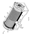
- FIG. 1A is a representation of a mechanical winch with a rope, according to one embodiment.
- FIG. 1B illustrates the mechanical winch of FIG. 1A , with bulging of the rope near the guiding mechanism.
- FIG. 2 is a magnified view of the rope of FIG. 1A with an inner core and outer sheath according to one embodiment.
- FIG. 3 is a sectional view of the rope of FIG. 2 , according to one embodiment, depicting an inner core with a non-planar surface.
- FIG. 4 is a sectional view of the rope of FIG. 2 , according to one embodiment, depicting an inner core with a non-planar surface and rings connected to an outer sheath.
- FIG. 5 is a sectional view of the rope of FIG. 2 , according to one embodiment, depicting an inner core with a non-planar surface in interaction with an outer sheath.
- FIG. 6 is a sectional view of the rope of FIG. 2 , according to one embodiment, depicting an inner core with a non-planar surface wherein inner strands are woven into an outer sheath
- a compressible rope may include an outer sheath surrounding an inner core, wherein the inner core includes a non-planar outer surface at least partially along its length that is in contact with the inner surface of the outer sheath.
- a mechanical winch may be used to let out or draw in a rope or line from a drum. To feed out the rope, the winch can put the rope under compressional forces. Such compressional forces can induce unraveling, separating, or bulging of either the inner or outer strands of rope. As a result of the separating strands, the rope can become tangled and the winch can become jammed. Such jamming can result not only disrupting the functional aspects of the winch, but can also decrease the longevity of the rope by creating snags or tears in the rope material.
- the non-planar surface of the inner core provides sufficient resistance to reduce the aforementioned separation of the strands. As a result of decreasing the likelihood of the strands separating, the rope is less likely to get tangled and the winch is less likely to jam.
- the rope may include one or more materials such as hemp, linen, flax, cellulose, carbon, wool, hair, feathers, cotton, coir, jute, straw, silk, sisal, polymers, nylon, Dyneema®, Kevlar®, rayon, orlon, polypropylene, polyesters, polyethylene, aramids, acrylics, copper, iron, steel, stainless steel, bronze, nichrome, carbon, solder, titanium, zinc, silver, gold, tungsten, or aluminum.
- the inner core comprises discontinuities at random or periodic locations along the length of the rope that can correspond with or be unrelated to any change in the material composition of the inner core.
- a sheath can be comprised of a plurality of tied, knotted, looped, twisted, braided, or woven outer strands, or combinations thereof.
- the sheath may encase the core while the core is under tension.
- Various embodiments of the outer sheath may include strand patterns or interactions that are distributed uniformly along the length of the rope.
- the strands of the outer sheath may have discontinuities in the patterns or interactions at random or periodic locations along the length of the rope corresponding with or unrelated to any change in the material composition of the sheath.
- the outer sheath may include rings, loops, bands, knots, or circles.
- an inner core may include a single strand or a plurality of strands. Additionally, according to various embodiments, the inner core may include a monofilament or polyfilament material, or a combination thereof. In various embodiments, one or more inner strands can be tied, knotted, looped, twisted, braided, woven, or any combination thereof. In various embodiments, one or more inner strands are tied, knotted, looped, twisted, braided, or woven uniformly along the length of the core. In other embodiments, the pattern or interconnections of the inner core strands have a discontinuous distribution along the length of the rope. Various embodiments may include discontinuities that correspond with or are unrelated to any change in the material composition of the inner core. The inner core, according to various embodiments, may be under tension after being encased by the sheath.
- the inner core may include a roughened or non-planar surface at least partially along its length.
- the non-planar surface may comprise a plurality of undulations, spirals, depressions, perforations, excrescences, protrusions, protuberances, or papillae.
- the non-planar surface can occur periodically, measuredly, irregularly, or sporadically along at least a portion of the inner core.
- Some embodiments may include a non-planar surface that is comprised of a plurality of inconsistencies such as knots, bulges, swellings, or lumps at least partially along the length of rope.
- the inconsistencies created by knots, bulges, swellings, or lumps may be due to a relatively thicker material, tangled masses associated with knots, loosely woven strands, or combinations thereof.
- Various embodiments may also include an inner core comprising one or more rings, loops, bands, or circles distributed intermittently along the non-planar surface.
- the interaction between the sheath and the inner core may be static or dynamic depending on the materials used, the distribution of any discontinuities, or other characteristics made possible by having a non-planar inner core. This interaction may reduce in the occurrence of unintended bunching, untying, separating, or slipping between the sheath and the inner core at least partially along the length of the rope.
- Cordage may also be referred to herein as a “rope” and may refer to any rope, line, cord, or cable that can be used for dragging or lifting.
- the term “strand” is broad enough to refer to any suitable fiber, filament, thread, yarn, wire, or any other threadlike material. Multiple strands combine to form a sheath around a core.
- the term “sheath” may refer to any close-fitting case or covering.
- core is used in its ordinary sense, and is broad enough to refer to the central or innermost portion of a rope.
- Some embodiments can be particularly suited to function with the assistance of a mechanical winch to drag or lift an object.
- mechanical winch generally refers to a mechanical device that uncoils or coils cordage.
- FIG. 1A is a representation of a mechanical winch 100 with a rope 110 , according to one embodiment.
- the mechanical winch 100 includes a drum 102 for coiling a rope 110 .
- the mechanical winch 100 also includes a guiding mechanism 104 for guiding the rope 110 onto or off of the drum 102 .
- Motorized gears 106 operate to rotate the drum 102 such that it can draw in or let out the rope 110 .
- the guiding mechanism 104 can move along a dial 108 such that there is a uniform distribution of the rope 110 as it coils around the drum 102 .
- the rope 110 includes an outer sheath 112 and an inner core 114 . This rope 110 is cut in a manner so as to illustrate the two layers of the rope 110 .
- FIG. 1B illustrates the mechanical winch 100 of FIG. 1A , with bulging 117 of the rope 110 near the guiding mechanism 104 .
- the bulging 117 can be induced when the rope 110 is subjected to compressional forces as the rope 110 is being let out.
- the bulging 117 can cause the rope to become tangled and/or caught in the guiding mechanism 104 resulting in a jammed mechanical winch 100 .
- FIG. 2 is a magnified view of the rope 110 of FIG. 1 , with an inner core 114 and outer sheath 112 according to one embodiment.
- the outer sheath 112 includes a plurality of braided strands 218 , but such strands 218 can be tied, knotted, looped, twisted, or woven as well.
- the inner core 114 may include one or more inner stands 216 that are of a monofilament or polyfilament material.
- the inner strands 216 of the present embodiment are depicted as being twisted, but can also be tied, knotted, looped, braided, or woven, or any combination thereof.
- FIG. 3 is a sectional view of the rope 110 of FIG. 2 , according to one embodiment, depicting an inner core 114 with a non-planar surface 320 .
- An outer sheath 112 flanks the inner core 114 .
- the non-planar surface 320 includes a plurality of protuberances 322 at least partially along its length. Such protuberances 322 may be of the same or a different material composition than the inner strands 216 .
- FIG. 4 is a sectional view of the rope 110 of FIG. 2 , according to one embodiment, depicting an inner core 114 with a non-planar surface 320 and rings 430 connected to an outer sheath 112 .
- the inner core 114 includes a plurality of knots 432 separated by the interconnected loops 430 .
- the interconnected loops 430 may be of a small enough diameter 434 to prevent the knots 432 from passing through the rings 430 .
- FIG. 5 is a sectional view of the rope 110 of FIG. 2 , according to one embodiment, depicting an inner core 114 with a non-planar surface 320 in interaction with an outer sheath 112 .
- the inner core 114 may contain bulges 540 separated by compressions 542 in the outer sheath 112 .
- the compressions 542 in the outer sheath 112 may be a result of the material of the outer sheath 112 , or a commingling of inner strands 216 in the inner core 114 with strands 218 of the outer sheath 112 .
- FIG. 6 is a sectional view of the rope 110 of FIG. 2 , according to one embodiment, depicting an inner core 114 with a non-planar surface 320 wherein inner strands 216 are woven into an outer sheath 112 .
- the inner strands 216 may be of the same continuous thread 650 as the braided strands 218 of the outer sheath 112 .
- the inner strands 216 may be connected to the braided strands 218 by ties, knots, loops, twists, braids, weaves, or any combination thereof.
Landscapes
- Ropes Or Cables (AREA)
Abstract
Description
Claims (20)
Priority Applications (1)
| Application Number | Priority Date | Filing Date | Title |
|---|---|---|---|
| US15/245,833 US10246823B2 (en) | 2016-07-11 | 2016-08-24 | Compressible rope |
Applications Claiming Priority (2)
| Application Number | Priority Date | Filing Date | Title |
|---|---|---|---|
| US201662360563P | 2016-07-11 | 2016-07-11 | |
| US15/245,833 US10246823B2 (en) | 2016-07-11 | 2016-08-24 | Compressible rope |
Publications (2)
| Publication Number | Publication Date |
|---|---|
| US20180010296A1 US20180010296A1 (en) | 2018-01-11 |
| US10246823B2 true US10246823B2 (en) | 2019-04-02 |
Family
ID=60892573
Family Applications (1)
| Application Number | Title | Priority Date | Filing Date |
|---|---|---|---|
| US15/245,833 Expired - Fee Related US10246823B2 (en) | 2016-07-11 | 2016-08-24 | Compressible rope |
Country Status (1)
| Country | Link |
|---|---|
| US (1) | US10246823B2 (en) |
Families Citing this family (4)
| Publication number | Priority date | Publication date | Assignee | Title |
|---|---|---|---|---|
| CN108316028A (en) * | 2018-03-20 | 2018-07-24 | 海城正昌工业有限公司 | A kind of steel wire rope composite fiber core and the preparation method and application thereof |
| CN110117916A (en) * | 2019-05-16 | 2019-08-13 | 厦门艺盟塑胶制品有限公司 | A kind of mountain-climbing dynamic ropes and its manufacturing method |
| CN110670233B (en) * | 2019-11-05 | 2021-06-04 | 山东鲁普科技有限公司 | Light wear-resistant multifunctional composite power single rope and manufacturing method thereof |
| US20220195799A1 (en) * | 2020-12-22 | 2022-06-23 | Ashot Aroian | Reflective Rope Ladder |
Citations (5)
| Publication number | Priority date | Publication date | Assignee | Title |
|---|---|---|---|---|
| US4640178A (en) * | 1984-02-01 | 1987-02-03 | Teufelberger Gesellschaft M.B.H. | Rope |
| US5301595A (en) * | 1992-06-25 | 1994-04-12 | General Motors Corporation | High temperature rope seal type joint packing |
| US5911675A (en) * | 1997-09-11 | 1999-06-15 | Bridgestone Corporation | Steel cord for reinforcing rubber product and pneumatic tire using such steel cord |
| US20100162882A1 (en) * | 2007-08-14 | 2010-07-01 | Shakespeare William C | Arborist's climbing rope |
| US20110197564A1 (en) * | 2008-10-23 | 2011-08-18 | Polteco Inc. | Abrasion resistant cords and ropes |
-
2016
- 2016-08-24 US US15/245,833 patent/US10246823B2/en not_active Expired - Fee Related
Patent Citations (5)
| Publication number | Priority date | Publication date | Assignee | Title |
|---|---|---|---|---|
| US4640178A (en) * | 1984-02-01 | 1987-02-03 | Teufelberger Gesellschaft M.B.H. | Rope |
| US5301595A (en) * | 1992-06-25 | 1994-04-12 | General Motors Corporation | High temperature rope seal type joint packing |
| US5911675A (en) * | 1997-09-11 | 1999-06-15 | Bridgestone Corporation | Steel cord for reinforcing rubber product and pneumatic tire using such steel cord |
| US20100162882A1 (en) * | 2007-08-14 | 2010-07-01 | Shakespeare William C | Arborist's climbing rope |
| US20110197564A1 (en) * | 2008-10-23 | 2011-08-18 | Polteco Inc. | Abrasion resistant cords and ropes |
Also Published As
| Publication number | Publication date |
|---|---|
| US20180010296A1 (en) | 2018-01-11 |
Similar Documents
| Publication | Publication Date | Title |
|---|---|---|
| US10246823B2 (en) | Compressible rope | |
| US8136438B2 (en) | Arborist's climbing rope | |
| EP2423379B1 (en) | Climbing rope comprising two braided layers | |
| US9499938B2 (en) | Mechanical method for creation of a splice in a coverbraided rope and products | |
| EP2913434B1 (en) | A process for forming an eye in a rope end | |
| CN100427673C (en) | Endless rope | |
| NO20210582A1 (en) | Braided rope for pelagic trawls | |
| CN110952354A (en) | Multilayer braided rope with tail end protection function and preparation method thereof | |
| US3400628A (en) | Flexible weight line and method of making weight line | |
| JP4647373B2 (en) | Manufacturing method of braid and fishing line made of braid | |
| US20140260927A1 (en) | Twelve-strand rope employing jacketed sub-ropes | |
| KR20120014884A (en) | Snood | |
| US3325990A (en) | Ropes and methods of making the same | |
| JP6366551B2 (en) | Cord yarn with excellent wear resistance and flexibility | |
| KR101608173B1 (en) | Weave weaving apparatus and lead to weave the rope for interpolated phrase | |
| RU2368714C1 (en) | Synthetic rope | |
| JP2002088625A (en) | Braid | |
| JP2554843B2 (en) | Trunk line for longline | |
| JP3015534U (en) | Longline for tuna fishing | |
| US20210156085A1 (en) | Hybrid hoisting cable, method of forming the same, and winch using such a cable | |
| DK201870322A1 (en) | Process for splicing coverbraided ropes having at least one eye | |
| CN113308918A (en) | Wire rope left-hand twisting structure for non-rotating hanging basket | |
| JP3161775U (en) | fishing line | |
| CN103233379A (en) | Flat woven steel rope sling | |
| JPH08205735A (en) | Main line for long line and fishline |
Legal Events
| Date | Code | Title | Description |
|---|---|---|---|
| AS | Assignment |
Owner name: HALL LABS LLC, UTAH Free format text: ASSIGNMENT OF ASSIGNORS INTEREST;ASSIGNOR:HALL, DAVID R.;REEL/FRAME:047058/0053 Effective date: 20180911 |
|
| AS | Assignment |
Owner name: HALL LABS LLC, UTAH Free format text: ASSIGNMENT OF ASSIGNORS INTEREST;ASSIGNOR:HALL, DAVID R.;REEL/FRAME:047132/0022 Effective date: 20180911 |
|
| AS | Assignment |
Owner name: HALL LABS LLC, UTAH Free format text: ASSIGNMENT OF ASSIGNORS INTEREST;ASSIGNOR:FOX, JOE;REEL/FRAME:047157/0931 Effective date: 20180811 Owner name: HALL LABS LLC, UTAH Free format text: ASSIGNMENT OF ASSIGNORS INTEREST;ASSIGNOR:MILES, JEROME;REEL/FRAME:047157/0172 Effective date: 20180619 |
|
| AS | Assignment |
Owner name: HALL LABS, LLC, UTAH Free format text: ASSIGNMENT OF ASSIGNORS INTEREST;ASSIGNOR:TAYLOR, BENJAMIN;REEL/FRAME:047758/0331 Effective date: 20181205 |
|
| STCF | Information on status: patent grant |
Free format text: PATENTED CASE |
|
| AS | Assignment |
Owner name: HALL LABS LLC, UTAH Free format text: ASSIGNMENT OF ASSIGNORS INTEREST;ASSIGNOR:FOX, JOE;REEL/FRAME:060392/0783 Effective date: 20220622 |
|
| FEPP | Fee payment procedure |
Free format text: MAINTENANCE FEE REMINDER MAILED (ORIGINAL EVENT CODE: REM.); ENTITY STATUS OF PATENT OWNER: SMALL ENTITY |
|
| LAPS | Lapse for failure to pay maintenance fees |
Free format text: PATENT EXPIRED FOR FAILURE TO PAY MAINTENANCE FEES (ORIGINAL EVENT CODE: EXP.); ENTITY STATUS OF PATENT OWNER: SMALL ENTITY |
|
| STCH | Information on status: patent discontinuation |
Free format text: PATENT EXPIRED DUE TO NONPAYMENT OF MAINTENANCE FEES UNDER 37 CFR 1.362 |
|
| FP | Lapsed due to failure to pay maintenance fee |
Effective date: 20230402 |