EP0905024B1 - Gerät zum Spannen und Abschneiden von Kabelbändern - Google Patents
Gerät zum Spannen und Abschneiden von Kabelbändern Download PDFInfo
- Publication number
- EP0905024B1 EP0905024B1 EP98117040A EP98117040A EP0905024B1 EP 0905024 B1 EP0905024 B1 EP 0905024B1 EP 98117040 A EP98117040 A EP 98117040A EP 98117040 A EP98117040 A EP 98117040A EP 0905024 B1 EP0905024 B1 EP 0905024B1
- Authority
- EP
- European Patent Office
- Prior art keywords
- cylinder
- gripper
- piston
- cable tie
- piston units
- Prior art date
- Legal status (The legal status is an assumption and is not a legal conclusion. Google has not performed a legal analysis and makes no representation as to the accuracy of the status listed.)
- Expired - Lifetime
Links
Images


Classifications
-
- B—PERFORMING OPERATIONS; TRANSPORTING
- B65—CONVEYING; PACKING; STORING; HANDLING THIN OR FILAMENTARY MATERIAL
- B65B—MACHINES, APPARATUS OR DEVICES FOR, OR METHODS OF, PACKAGING ARTICLES OR MATERIALS; UNPACKING
- B65B13/00—Bundling articles
- B65B13/02—Applying and securing binding material around articles or groups of articles, e.g. using strings, wires, strips, bands or tapes
- B65B13/025—Hand-held tools
- B65B13/027—Hand-held tools for applying straps having preformed connecting means, e.g. cable ties
-
- B—PERFORMING OPERATIONS; TRANSPORTING
- B65—CONVEYING; PACKING; STORING; HANDLING THIN OR FILAMENTARY MATERIAL
- B65B—MACHINES, APPARATUS OR DEVICES FOR, OR METHODS OF, PACKAGING ARTICLES OR MATERIALS; UNPACKING
- B65B13/00—Bundling articles
- B65B13/18—Details of, or auxiliary devices used in, bundling machines or bundling tools
- B65B13/185—Details of tools
- B65B13/187—Motor means
- B65B13/188—Motor means pneumatic or hydraulic
Definitions
- the invention relates to a device for clamping and cutting with Plastic ribbons provided with cross corrugations, in particular cable ties for binding cable bundles, pipes and the like. Elongated objects.
- the Device consists of a housing with a pressure-operated one Cylinder-piston unit with longitudinally displaceable gripper, through which it moves back and forth movement the one inserted through the mouthpiece of the device End of the cable band detectable and provided in one at the other end Locking part can be tightened in sections, as well as from an over a pressure medium-actuated drive movable knife to cut the am Locking part protruding section of the cable tie when reaching a predetermined tightening force.
- a device with a pneumatic drive is known from EP 0 733 549 A1 .
- a gripper arranged behind the mouthpiece is moved back and forth again in several strokes over the piston of a pneumatic cylinder-piston unit until a certain tightening force is reached , with the gripper grasping the free end of the cable strap for each working stroke and releasing it for each return stroke.
- the cable strap is tightened in sections.
- the pressure medium is reversed by a pneumatically controlled valve arrangement, and a knife is actuated via a second piston of the cylinder-piston unit, which cuts off the section of the cable strap projecting from the locking part behind the mouthpiece of the device.
- the cut part of the cable tape runs on a slope inside the device and can be ejected upwards.
- the device works relatively slowly.
- the piston moving the gripper in order to tighten the cable band in sections, for each of these sections make a full, reciprocating stroke, with the return stroke on Idle stroke during which the cable strap is not tightened.
- the return stroke on Idle stroke during which the cable strap is not tightened.
- the protruding section of the cable tape during the return stroke the mouthpiece is pulled out, because it is not in this phase of the gripper or another part is held.
- the object of the invention is to provide a device of the type mentioned that works efficiently in short work cycles, reliably and trouble-free Empty strokes are avoided and work strokes do not have to be repeated.
- the Removing and collecting the accumulated waste may attract the operator's attention not particularly demanding.
- the operation must be energy-saving and be gentle.
- the required Working time for tightening a cable tape can be practically halved; the The span length then corresponds to twice the stroke of the gripper or Pistons in the cylinder-piston units. Since the required number of measures for halved a certain span length, there is immediately a higher life expectancy the moving parts of the device.
- gripper is movable according to claim 4 on longitudinally movable carriage are mounted, both the secure gripping of the gripper on the cable tie when Reverse stroke, as well as the sliding of the grippers over the cable tie at Forward stroke effectively supported.
- the effective surfaces of the grippers according to claim 5 are partly by rakes trained guide parts protrude and can be moved therein lift the cable strap advanced in the device from the guide parts be so that the cable band gets stuck in the device and consequent Disruptions can be avoided.
- the ejector can be the section of the cable tie cut off at the end of a working cycle transported as waste to a collection container integrated in the device, collected there and be recycled.
- the operating cycle of the device can be triggered by an actuator and then run programmatically according to claims 10 to 15. So lets the cable band tighten up to a certain tightening force, the protruding one Then cut the piece off and put it in a container, after which all parts of the device are returned to the starting position, so that the device is ready for a new operation.
- the cylinder-piston units during the cutting process according to claim 11 program-controlled depressurized, so can hold a hold-down the knife, because then there will be no force on the cable strap exercised, which could disrupt or hinder the cutting process.
- a maximum number of strokes per work cycle can be specified so that no unintentional continuous operation of the device can occur; over a End position query can ensure the return of the parts to their starting position become.
- Cable straps of different sizes can be processed with the device.
- Your Thickness can be 0.8 to 1.8 mm and its width 4 to 8 mm.
- Your length will be in essentially limited by the length of the collecting container; but it is at least up to 150 mm.
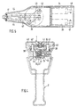
- the housing of the illustrated embodiment of the invention has a pistol shape with an elongated housing part 1 and a handle 2 with an actuator 3.
- the electronics or part of the electronics for controlling the device is accommodated on a circuit board 4 .
- two boards for the electronic control can be accommodated in the rear part of the housing part 1 .
- a cutting device for cutting off the protruding cable section. It consists of an interchangeable knife 7 held directly behind the mouthpiece 5 of the device in a guide 6 and vertically displaceable against a shear bar.
- the guide 6 of the knife 7 is connected to the one free end of a two-armed rocker arm 8 .
- the rocker arm 8 can be pivoted about a fixed axis 9 and is connected at its other free end to the piston rod 10 of a pneumatically actuable drive unit 11 which can be actuated to actuate the knife 7 .
- a link guide is provided at the connection between the end of the rocker arm 8 and the piston rod 10 .
- the connecting pin 12 can slide between the piston rod 10 and the rocker arm 8 when the drive unit 11 is actuated in an obliquely extending slot 13 , so that a displacement of the piston connected to the piston rod 10 causes a rocking movement of the rocker arm 8 and thus the actuation of the knife 7 .
- a longitudinally displaceable first slide 15 is arranged above the cutting device.
- a gripper 16 is arranged in a recess 18 , the active surface of which has saw teeth 17 .
- the cutout 18 and the gripper 16 essentially have a triangular shape in the sectional illustration in FIG. 1.
- the gripper 16 is slidably guided on the front bevel of the recess 18 forming a sliding surface 19 and on a connecting pin 20 running parallel thereto between the opposing, rear oblique surfaces of the gripper 16 and the recess 18 .
- an elongated hole 21 running parallel to the sliding surface 19 is provided in the gripper 16 , into which a guide pin 22 , which is fixedly connected to the slide 15 , projects.
- the saw teeth 17 of the gripper 16 are held in abutment on the opposite surface of a front guide part 24 or on the surface of an end section of a cable band 50 which is inserted and drawn through the mouthpiece 5 and which is guided on the guide part 24 . 1 this is achieved by a helical spring 23 which surrounds the connecting pin 20 and is supported on the opposing inclined surfaces of the gripper 16 and the recess 18 .
- the length of the guide part 24 corresponds approximately to the movement stroke of the slide 15 or the piston stroke of the pneumatic drive.
- a second carriage 25 with a second gripper 26 at its front end whose saw teeth 27 in the same manner as described above, but mirror image of the first gripper 16 on one inserted cable band 50 are held in plant.
- the interruption between the front guide part 24 and the second slide 25 is preferably bridged by a baffle plate 14 which slides over the front guide part 24 during the forward stroke (see below) of the second slide 25 .
- the retracted cable end is directed in the direction of the second gripper 26 and the ejection channel 30 .
- This guide part 28 has a forward inclined slope at its front end, at which the end portion of a retracted cable band 50 can run to enter the gap between this second guide part 28 and the second gripper 26 and then into that between the second guide part 28 and a cover 29 formed channel 30 to be directed.
- This channel 30 opens into a collecting container 31 in the rear, lower part of the housing part 1. The cut cable strip sections are collected there as waste and sent for recycling.
- the second guide part 28 is advantageously designed as a rake 32 (see also FIG. 4), between the sides of which an ejector 45 articulated at the rear end of the first carriage 15 can pass (see also FIG. 6) Channel 30 and passed into the collecting container 31 .
- the surface of the gripper 16 carrying the saw teeth 17 is comb-shaped in the cross-sectional direction and, when the device is operated with the ejector 45 (see FIG. 6), runs a certain distance through the rake 32 of the second guide part 28 in order to raise the cable band section.
- the saw teeth 27 of the second gripper 26 can be designed in the same way as a comb and then run between the frames of a similar rake 32 ' or a grid in the section of the front guide part 24 and / or the cover 29 protruding in the range of movement of the second gripper 26 , so that the cable section is also safely guided into the channel 30 and the collecting container 31 from this side.
- the collecting container 31 can be emptied by opening a protective top 49 articulated on the housing (FIG. 7).
- two pneumatically actuable cylinder-piston units 33, 34 and a pneumatic valve arrangement 35 which provide the pneumatic drive for the device, are accommodated in parallel in the rear housing part 1 above the collecting container 31 , that is, the reciprocating movement of the two slides 15, 25, and the cutting process.
- a two-armed rotary lever 36 is provided in the center under the housing cover, the two free ends of which are each connected to the piston rod 37, 38 of one of the two cylinder-piston units 33, 34 and to one of the two slides 15, 25 . While the device is being operated, the rotary lever 36, as indicated in FIG. 2, can assume two end positions rotated relative to one another by approximately 90 °, in each of which the piston rod 37 or 38 of the one cylinder-piston unit 33 or 34 is fully extended and the the other is completely withdrawn.
- Fig. 4 shows the cross section along the section line IV - IV through the device, in the middle position of the rotary lever 36 according to Fig. 2.
- the piston rods 37, 38 are each laterally connected to a bearing piece 39, 39 ', and these are between the two free ends of the rotary lever 36 and an underlying slide part 40, 41 of the carriage 15, 25 are arranged.
- the bearing pieces 39, 39 ' are perpendicularly pierced by connecting pins 42, 42' which are firmly connected at one end to the slide parts 40, 41 and protrude at their other end into an elongated hole 43, 43 'of the free ends of the rotary lever 36 and can slide in it.
- These elongated holes 43, 43 ' can also be open on one side to facilitate assembly, as indicated in FIG. 4, so that the ends of the rotary lever 36 appear fork-shaped (see FIG. 5).
- the slide part 40 of the upper slide 25 extends from its connection point with the connecting pin 42 under the rotary lever 36 to the center and is there firmly connected to the upper slide 25 at its rear end, for example screwed.
- the sliding gate! 41 of the lower carriage 15 is bent at the connection point with the connecting pin 42 ' downwards and forwards and engages under the carriage 15 at its rear end again at an angle at which the connection is made.
- the slide part 41 broken away in the area of the upper gripper 26 , can also be seen in FIG. 1.
- the carriages 15 and 25 can have a T-shaped cross-sectional shape according to FIG. 4 and are guided in mirror-image fashion relative to one another in guides, for example rails 44 (see also FIG. 5) fastened in the housing.
- guides for example rails 44 (see also FIG. 5) fastened in the housing.
- the rakes 32, 32 'of the rear guide part 28 and the cover 29 can be seen, between the sides of which the ejector 45 and the saw teeth 17 of the lower one Carriage 15 carried by gripper 16 on the one hand and saw teeth 27 of the gripper 26 carried by upper carriage 25 on the other hand pass through when the device is actuated.
- the device is operated pneumatically; the compressed air supply takes place, as indicated in Fig. 1 at 46 , from below through the handle 2 to the valve assembly 35 and the compressed air connections 47, 48 of the cylinder-piston units 33, 34 and the connection of the drive unit 11 for the knife 7. If that If the device is to be suspended from a work station and kept within reach, it may be more advantageous to supply the compressed air from above through the housing ceiling.
- the device works as follows:
- the starting positions of the moving parts of the device are shown with solid lines; an intermediate position and the other end position of the moving parts are indicated by dash-dotted lines.
- the front carriage 15 together with the gripper 16 is in its foremost position directly behind the opening of the mouthpiece 5, and the second carriage 25 with the gripper 26, which is offset to the rear, is in its retracted position on the cover 29 (see in this regard) Fig. 6).
- the piston rod 37 of the cylinder-piston unit 33 connected to the front slide 15 is fully extended, the piston rod 38 of the cylinder-piston unit 34 connected to the second slide 25 is fully retracted into the cylinder (see FIG. 2).
- a cable band 50 wrapped around a cable bundle or corrugated tube (see FIG. 6), after it has been pulled through a locking part 51 , is inserted so far into the mouthpiece 5 of the device that the band end is removed from the saw teeth 17 of the front and through the coil spring 23 in the direction of the front guide part 24 loaded gripper 16 is gripped and pressed against the guide part 24 and held.
- the cable band 50 is provided in a known manner with a corrugation and with lateral guide beads, as a result of which it is securely gripped by the gripper 16 and then moved and is also guided securely on the guide part 24 .
- the two cylinder-piston units 33, 34 are first program-pressurized with compressed air via the valve arrangement 35 such that the piston rod 37 of the cylinder-piston unit 33 is retracted and at the same time the piston rod 38 of the cylinder-piston - Unit 34 is extended.
- the rotary lever 36 is rotated from its initial position according to FIG. 2 by about 90 ° into its other end position and the longitudinal movement of the two piston rods 37, 38 is transmitted to the two slides 15 and 25 by the rotary lever 36 via the slide parts 40, 41 .
- the carriage 15 thus moves together with the gripper 16 , taking the cable band end 50 gripped by the gripper 16 into its retracted end position (see FIG.
- the action on the pneumatic cylinder-piston units 33, 34 is then reversed, and all parts move back to their starting position, the gripper 26 of the second carriage 25 now attacking the cable band 50 with its saw teeth 27 and again when it moves backward takes along the length of a piston stroke. Now the saw teeth 17 of the gripper 16 slide on the front carriage 15 as they move forward over the cable band 50 without exerting any force. This cycle is repeated until a predetermined tightening force is reached on the cable strap 50 . This can be set up to 150 N in 15 steps, for example.
- the cable band 50 is alternately tightened by the two cylinder-piston units 33, 34 by, for example, 42-45 mm with each piston stroke, without an idle stroke taking place. The time required to tighten a cable band is thus halved.
- the pressure medium supply to the cylinder-piston units is interrupted and a further valve is activated, which then releases the compressed air supply to the drive unit 11 of the knife 7 , whereupon the latter operates the knife 7 , for example against a spring force via the rocker arm 8 , and the protruding section of the cable band 50 is cut off just behind the opening of the mouthpiece 5 .
- the two cylinder-piston units 33 and 34 are preferably temporarily depressurized under program control; This has the advantage that a hold-down device for the cable band 50 on the knife 7 can be dispensed with for the cutting process.
- the work cycle is brought to an end by returning all moving parts to their starting position according to the program with an idle stroke after the ejector 45 and the second gripper 26 remove the severed section of the cable band 50 through the channel 30 between the rear guide member 28 and the cover 29 into the collecting container 31 .
- the position of the drive piston is queried by sensors in the housing. Only when they are back in their starting position, the work cycle is ended and the device is ready for a new operation.
- Limit switches preferably two light barriers, can serve as sensors for the end position query.
- cable ties with a Thickness of 0.8 - 1.8 mm, a width of 4 - 8 mm and a length of at least Process 150 mm With the device described above as an example, cable ties with a Thickness of 0.8 - 1.8 mm, a width of 4 - 8 mm and a length of at least Process 150 mm.
- the maximum tightening force reaches up to 150 N and is in several Levels adjustable.
- the pneumatic-mechanical drive that is to say the cylinder-piston units 33, 34 together with the rotary lever 36 with the slide parts 40, 41, can also be arranged laterally one above the other in the housing for reasons of space.
- the arrangement described above has the advantage that the device is better balanced overall and so the operator's wrist is less stressed; the opposing masses in the device ensure very smooth running.
Landscapes
- Engineering & Computer Science (AREA)
- Mechanical Engineering (AREA)
- Basic Packing Technique (AREA)
- Manipulator (AREA)
- Removal Of Insulation Or Armoring From Wires Or Cables (AREA)
Description
- Fig. 1
- einen Längsschnitt durch ein erfindungsgemäßes Gerät,
- Fig. 2
- die wichtigsten Teile des Antriebs des Gerätes nach Fig. 1 von oben gesehen in verschiedenen Arbeitsstellungen, wobei die Gehäusedecke teilweise weggebrochen ist,
- Fig. 3
- Teile des Antriebs für das Messer im vorderen Teil des Gerätes von oben gesehen,
- Fig. 4
- einen Querschnitt durch das Gerät entlang der Schnittlinie IV - IV in Fig. 2,
- Fig. 5
- Teile der Schlittenführung in einer Sicht von oben in das Gerät bei weggebrochener Decke,
- Fig. 6
- in einem Längsschnitt durch den vorderen Teil des Gerätes verschiedene Stellungen der Greifer während eines Arbeitszyklus und
- Fig. 7
- das Gehäuse des Gerätes mit hochklappbarem Schutzverdeck.
Claims (15)
- Gerät zum Spannen und Abschneiden von mit Querriffelungen versehenen Kunststoffbändern, insbesondere Kabelbändern, bestehend aus einem Gehäuse mit einem durch eine Druckmittel-betätigte Zylinder-Kolben-Einheit darin längs verschiebbaren Greifer, durch dessen hin- und hergehende Bewegung das eine durch ein Mundstück (5) des Gerätes eingeführte Ende des Kabelbandes (50) erfaßbar und in einem an dessen anderem Ende vorgesehenen Verriegelungsteil (51) abschnittsweise festziehbar ist, und aus einem quer zur Bandrichtung bewegbaren Messer (7) zum Abtrennen des am Verriegelungsteil überstehenden Abschnittes des Kabelbandes,
dadurch gekennzeichnet, daß im Gehäuse (1) spiegelbildlich zu dem einen längs verschiebbaren Greifer (16) in Längsrichtung zu diesem nach hinten versetzt ein zweiter längs verschiebbarer Greifer (26) angeordnet ist, daß die beiden Greifer (16, 26) gegenläufig hin- und herbewegbar sind und jeweils während ihres Rückwärtshubes an den entgegengesetzten Flächen des durch das Mundstück (5) eingeführten Kabelbandes (50) abwechselnd in Eingriff bringbar sind, und daß jeder der Greifer (16, 26) antriebsmäßig mit einer von zwei Zylinder-Kolben-Einheiten (33, 34) verbunden ist, die im Gegentakt mit Druckmittel zu einer hin- und hergehenden Bewegung beaufschlagbar sind. - Gerät nach Anspruch 1, dadurch gekennzeichnet, daß in Ausgangstellung des Gerätes der zweite Greifer (26) gegenüber dem ersten Greifer (16) um den doppelten Bewegungshub nach hinten versetzt ist.
- Gerät nach Anspruch 1 oder 2, dadurch gekennzeichnet, daß die Wirkflächen der Greifer (16, 26) mit einwärts gerichteten Sägezähnen (17, 27) versehen sind, welche den Querriffelungen des Kabelbandes entsprechen.
- Gerät nach einem der Ansprüche 1 bis 3, dadurch gekennzeichnet, daß die Greifer (16, 26) jeweils am vorderen Ende von zwei in Führungen (44) längs verschiebbaren Schlitten (15, 25) angeordnet und daran auf einer schrägen Gleitfläche (19) geführt sind und in Richtung auf ein ihnen entlang ihres jeweiligen Bewegungshubes gegenüberliegendes erstes (24) und zweites Führungsteil (28) für das Kabelband (50) vorgespannt sind.
- Gerät nach Anspruch 4, dadurch gekennzeichnet, daß ein in den Bewegungsbereich der Greifer (16, 26) hineinragender Abschnitt des sich in der Fortsetzung als Widerlager für den jeweils anderen Greifer (26, 16) erstreckenden Führungsteils (24, 28) als Rechen (32, 32') ausgebildet ist und die die Sägezähne (17, 27) tragende Wirkfläche der Greifer (16, 26) kammartig ausgebildet ist, so daß der jeweilige Greifer (16, 26) durch diesen Rechen (32, 32') bewegbar ist.
- Gerät nach Anspruch 5, dadurch gekennzeichnet, daß am dem vorderen Greifer (16) entgegengesetzten Ende des unteren Schlittens (15) ein Ausstoßer (45) angelenkt ist, der zwischen den Zargen des Rechens (32) am unteren Führungsteil (28) bewegbar ist und durch den der am Ende eines Arbeitszyklus durch das Messer (7) abgetrennte Abschnitt des Kabelbandes (50) durch einen sich an den Bewegungsbereich des hinteren Greifers (26) anschließenden Kanal (30) in einen Auffangbehälter (31) beförderbar ist.
- Gerät nach einem der Ansprüche 4 bis 6, dadurch gekennzeichnet, daß die Greifer (16, 26) bzw. die sie tragenden Schlitten (15, 25) jeweils mit den Kolbenstangen (37, 38) zweier, im Gegentakt beaufschlagbarer Zylinder-Kolben-Einheiten (33, 34) antriebsmäßig verbunden sind, wobei in Ausgangsstellung des Gerätes sich die mit dem vorderen Schlitten (15) verbundene Kolbenstange (37) in ausgefahrenem Zustand befindet und die mit dem hinteren Schlitten (25) verbundene Kolbenstange (38) sich in zurückgezogenem Zustand befindet.
- Gerät nach Anspruch 7, dadurch gekennzeichnet, daß die Zylinder-Kolben-Einheiten (33, 34) parallelliegend angeordnet sind und die freien Enden eines im Gehäuse verdrehbar angeordneten, zweiarmigen Drehhebels (36) einerseits mit an den Schlitten (15, 25) befestigten Schieberteilen (40, 41) und andererseits mit den Kolbenstangen (37, 38) der Zylinder-Kolben-Einheiten (33, 34) verbunden sind und jeweils ein in einem Langloch (43, 43') der freien Enden des Drehhebels (36) gleitend geführter Verbindungsstift (42, 42') sowohl mit einer der Kolbenstangen (37, 38) als auch mit dem Schieberteil (40, 41) eines der Schlitten (15, 25) fest verbunden ist.
- Gerät nach einem der vorangehenden Ansprüche, dadurch gekennzeichnet, daß das in einer Führung (6) gehaltene Messer (7) zum Abtrennen des am Verriegelungsteil (51) überstehenden Kabelbandabschnittes über das eine freie Ende eines im vorderen Gehäuseteils (1) drehbar gelagerten Wipphebels (8) betätigbar ist, dessen anderes freie Ende mit dem Kolben einer Antriebseinheit (11) verbunden ist.
- Arbeitsverfahren zum Betätigen eines Gerätes nach Ansprüch 9, dadurch gekennzeichnet, daß der an einem Betätigungsglied (3) auslösbare Arbeitszyklus durch eine im Gehäuse untergebrachte Elektronik programmgesteuert wird und dabei in einer ersten Phase des Arbeitszyklus für die hin- und hergehende Bewegung der Schlitten (15, 25) bzw. Greifer (16, 26) die Kolben der Zylinder-Kolben-Einheiten (33, 34) über eine Ventilanordnung (35) abwechselnd in beide Richtungen und im Gegentakt mit Druckmittel beaufschlagt werden und daß der sich in den Zylinder-Kolben-Einheiten (33, 34) aufbauende Druck durch Drucksensoren gemessen wird und bei Erreichen eines einer bestimmten Anzugskraft am Kabelband (50) entsprechenden Drucks zur Einleitung einer zweiten Phase des Arbeitszyklus ein Signal erzeugt wird, durch das die Druckmittelzufuhr zu den Zylinder-Kolben-Einheiten (33, 34) unterbrochen und die Antriebseinheit (11) zur Betätigung des Messers (7) über ein Ventil mit Druckmittel beaufschlagt wird und daß nach vollzogenem Schneidevorgang ein Leerhub der Kolben der Zylinder-Kolben-Einheiten (33, 34) durchgeführt wird.
- Arbeitsverfahren nach Anspruch 10, dadurch gekennzeichnet, daß die Zylinder-Kolben-Einheiten (33, 34) während des Schneidevorgangs drucklos gestellt werden.
- Arbeitsverfahren nach Anspruch 10 oder 11, dadurch gekennzeichnet, daß die zu erreichende Anzugskraft am Kabelband (50) über den sich in den Zylinder-Kolben-Einheiten (33, 34) aufbauenden, durch Drucksensoren meßbaren Druck stufenweise einstellbar ist.
- Arbeitsverfahren nach Anspruch 12, dadurch gekennzeichnet, daß die Anzugskraft am Kabelband (50) in 5 oder 10 Stufen zwischen 0 und 150 N einstellbar ist.
- Arbeitsverfahren nach einem der Ansprüche 11 bis 14, dadurch gekennzeichnet, daß mit dem den Arbeitszyklus abschließenden Leerhub der Zylinder-Kolben-Einheiten (33, 34) deren Kolben wieder in ihre Ausgangsstellung zurückgeführt werden.
- Arbeitsverfahren nach Anspruch 14, dadurch gekennzeichnet, daß die Rückführung der Kolben der Zylinder-Kolben-Einheiten (33, 34) in ihre Ausgangstellung aufgrund einer Endlageabfrage über die Position der Kolben sichergestellt wird.
Applications Claiming Priority (2)
| Application Number | Priority Date | Filing Date | Title |
|---|---|---|---|
| DE19742293 | 1997-09-25 | ||
| DE19742293A DE19742293C2 (de) | 1997-09-25 | 1997-09-25 | Gerät zum Spannen und Abschneiden von Kabelbindern |
Publications (2)
| Publication Number | Publication Date |
|---|---|
| EP0905024A1 EP0905024A1 (de) | 1999-03-31 |
| EP0905024B1 true EP0905024B1 (de) | 2001-08-29 |
Family
ID=7843569
Family Applications (1)
| Application Number | Title | Priority Date | Filing Date |
|---|---|---|---|
| EP98117040A Expired - Lifetime EP0905024B1 (de) | 1997-09-25 | 1998-09-09 | Gerät zum Spannen und Abschneiden von Kabelbändern |
Country Status (3)
| Country | Link |
|---|---|
| EP (1) | EP0905024B1 (de) |
| DE (2) | DE19742293C2 (de) |
| ES (1) | ES2161499T3 (de) |
Families Citing this family (1)
| Publication number | Priority date | Publication date | Assignee | Title |
|---|---|---|---|---|
| CN109353258B (zh) * | 2018-11-21 | 2024-06-11 | 齐二伟 | 一种双缸复推式总成 |
Family Cites Families (3)
| Publication number | Priority date | Publication date | Assignee | Title |
|---|---|---|---|---|
| DE2300782C3 (de) * | 1973-01-08 | 1980-03-20 | Paul Hellermann Gmbh, 2080 Pinneberg | Werkzeug zum Spannen und Abschneiden eines mit einem Schloß versehenen, um einen Gegenstand gelegten Bandes |
| US3865156A (en) * | 1973-09-17 | 1975-02-11 | Panduit Corp | Powered strap tensioning and severing tool |
| DE29504940U1 (de) * | 1995-03-23 | 1996-07-18 | Paul Hellermann GmbH, 25421 Pinneberg | Werkzeug zum Spannen eines Bandes |
-
1997
- 1997-09-25 DE DE19742293A patent/DE19742293C2/de not_active Expired - Fee Related
-
1998
- 1998-09-09 ES ES98117040T patent/ES2161499T3/es not_active Expired - Lifetime
- 1998-09-09 EP EP98117040A patent/EP0905024B1/de not_active Expired - Lifetime
- 1998-09-09 DE DE59801295T patent/DE59801295D1/de not_active Expired - Fee Related
Also Published As
| Publication number | Publication date |
|---|---|
| EP0905024A1 (de) | 1999-03-31 |
| ES2161499T3 (es) | 2001-12-01 |
| DE19742293A1 (de) | 1999-04-08 |
| DE19742293C2 (de) | 1999-08-26 |
| DE59801295D1 (de) | 2001-10-04 |
Similar Documents
| Publication | Publication Date | Title |
|---|---|---|
| DE2723651C2 (de) | Werkzeug zum Vereinzelnen und Anbringen von Kabelbindern | |
| DE2545345C2 (de) | ||
| EP0377833B1 (de) | Greifvorrichtung zum Mitführen einer klebrigen Werkstoffbahn | |
| DE2753720C2 (de) | Verfahren und Einrichtung zum Verladen von aus einer horizontalen Ballenpresse ausgestoßenen Ballen | |
| EP0084680B1 (de) | Vorrichtung zum Umschnüren von Ballen in einer Ballenpresse | |
| DE2300782C3 (de) | Werkzeug zum Spannen und Abschneiden eines mit einem Schloß versehenen, um einen Gegenstand gelegten Bandes | |
| EP0281942A1 (de) | Entdrahtungsmaschine | |
| DE2838510A1 (de) | Werkzeug zum anbringen einer buendelschlinge | |
| DE3519356C2 (de) | Preßstempel-Reinigungsvorrichtung für eine Ballenpresse mit Zuführung von unten | |
| CH617636A5 (en) | Delivery device | |
| DE1586954A1 (de) | Verfahren und Vorrichtung zum Umreifen von expansionsfaehigen Guetern,wie Pressballen | |
| WO1986001974A1 (fr) | Procede et dispositif pour la confection de bottes a partir de vegetaux coupes | |
| DE3147566A1 (de) | "anlage zum aufarbeiten von fleisch" | |
| DE2816912C2 (de) | Schneidvorrichtung zum Durchtrennen von Verschnürungen | |
| DE2165664C3 (de) | Vorrichtung zum Umbinden von mehreren Gegenständen mit einer Bandschlaufe | |
| DE2749486C2 (de) | ||
| DE19742293C2 (de) | Gerät zum Spannen und Abschneiden von Kabelbindern | |
| EP4331828B1 (de) | Kanalballenpresse mit kreuzabbindung | |
| EP1231144A1 (de) | Anordnung zum Binden von Gegenständen mittels einer Bandschlaufe | |
| DE2847520A1 (de) | Fadenvorlegevorrichtung, insbesondere zum vorlegen von kettfaeden fuer das automatische einziehen derselben in litzen und lamellen einer webmaschine | |
| DE3204653C2 (de) | Vorrichtung zum Herstellen geschweißter Gitterträger | |
| DE4022324A1 (de) | Ballenpresse zum erstellen hochverdichteter, abgebundener ballen aus abfallmaterialien | |
| EP2478757A1 (de) | Ballenpresse | |
| DE2115667B2 (de) | Verpackungsvorrichtung für Abfallpresspakete | |
| DE3114911C2 (de) | Vorrichtung zum Abnehmen und Abstellen von frisch geformten Platten aus Beton o.dgl. |
Legal Events
| Date | Code | Title | Description |
|---|---|---|---|
| PUAI | Public reference made under article 153(3) epc to a published international application that has entered the european phase |
Free format text: ORIGINAL CODE: 0009012 |
|
| AK | Designated contracting states |
Kind code of ref document: A1 Designated state(s): DE ES FR GB IT |
|
| AX | Request for extension of the european patent |
Free format text: AL;LT;LV;MK;RO;SI |
|
| 17P | Request for examination filed |
Effective date: 19990930 |
|
| AKX | Designation fees paid |
Free format text: DE ES FR GB IT |
|
| GRAG | Despatch of communication of intention to grant |
Free format text: ORIGINAL CODE: EPIDOS AGRA |
|
| 17Q | First examination report despatched |
Effective date: 20000406 |
|
| GRAG | Despatch of communication of intention to grant |
Free format text: ORIGINAL CODE: EPIDOS AGRA |
|
| GRAH | Despatch of communication of intention to grant a patent |
Free format text: ORIGINAL CODE: EPIDOS IGRA |
|
| GRAH | Despatch of communication of intention to grant a patent |
Free format text: ORIGINAL CODE: EPIDOS IGRA |
|
| GRAA | (expected) grant |
Free format text: ORIGINAL CODE: 0009210 |
|
| AK | Designated contracting states |
Kind code of ref document: B1 Designated state(s): DE ES FR GB IT |
|
| REF | Corresponds to: |
Ref document number: 59801295 Country of ref document: DE Date of ref document: 20011004 |
|
| GBT | Gb: translation of ep patent filed (gb section 77(6)(a)/1977) |
Effective date: 20011018 |
|
| ET | Fr: translation filed | ||
| REG | Reference to a national code |
Ref country code: ES Ref legal event code: FG2A Ref document number: 2161499 Country of ref document: ES Kind code of ref document: T3 |
|
| REG | Reference to a national code |
Ref country code: GB Ref legal event code: IF02 |
|
| PLBE | No opposition filed within time limit |
Free format text: ORIGINAL CODE: 0009261 |
|
| STAA | Information on the status of an ep patent application or granted ep patent |
Free format text: STATUS: NO OPPOSITION FILED WITHIN TIME LIMIT |
|
| 26N | No opposition filed |
Opponent name: INSTITUT FUER VERBUNDWERKSTOFFE GMBH |
|
| PGFP | Annual fee paid to national office [announced via postgrant information from national office to epo] |
Ref country code: GB Payment date: 20040908 Year of fee payment: 7 |
|
| PGFP | Annual fee paid to national office [announced via postgrant information from national office to epo] |
Ref country code: ES Payment date: 20040913 Year of fee payment: 7 |
|
| PGFP | Annual fee paid to national office [announced via postgrant information from national office to epo] |
Ref country code: DE Payment date: 20050813 Year of fee payment: 8 |
|
| PG25 | Lapsed in a contracting state [announced via postgrant information from national office to epo] |
Ref country code: IT Free format text: LAPSE BECAUSE OF NON-PAYMENT OF DUE FEES Effective date: 20050909 Ref country code: GB Free format text: LAPSE BECAUSE OF NON-PAYMENT OF DUE FEES Effective date: 20050909 |
|
| PG25 | Lapsed in a contracting state [announced via postgrant information from national office to epo] |
Ref country code: ES Free format text: LAPSE BECAUSE OF NON-PAYMENT OF DUE FEES Effective date: 20050910 |
|
| GBPC | Gb: european patent ceased through non-payment of renewal fee |
Effective date: 20050909 |
|
| REG | Reference to a national code |
Ref country code: ES Ref legal event code: FD2A Effective date: 20050910 |
|
| PG25 | Lapsed in a contracting state [announced via postgrant information from national office to epo] |
Ref country code: DE Free format text: LAPSE BECAUSE OF NON-PAYMENT OF DUE FEES Effective date: 20070403 |
|
| PGFP | Annual fee paid to national office [announced via postgrant information from national office to epo] |
Ref country code: FR Payment date: 20080915 Year of fee payment: 11 |
|
| REG | Reference to a national code |
Ref country code: FR Ref legal event code: ST Effective date: 20100531 |
|
| PG25 | Lapsed in a contracting state [announced via postgrant information from national office to epo] |
Ref country code: FR Free format text: LAPSE BECAUSE OF NON-PAYMENT OF DUE FEES Effective date: 20090930 |