EP0904975A1 - Einrichtung für das Einstellen der Stelle eines Sitzes in ein Fahrzeug - Google Patents
Einrichtung für das Einstellen der Stelle eines Sitzes in ein Fahrzeug Download PDFInfo
- Publication number
- EP0904975A1 EP0904975A1 EP98203282A EP98203282A EP0904975A1 EP 0904975 A1 EP0904975 A1 EP 0904975A1 EP 98203282 A EP98203282 A EP 98203282A EP 98203282 A EP98203282 A EP 98203282A EP 0904975 A1 EP0904975 A1 EP 0904975A1
- Authority
- EP
- European Patent Office
- Prior art keywords
- main body
- seat
- clamping
- terminal blocks
- guide
- Prior art date
- Legal status (The legal status is an assumption and is not a legal conclusion. Google has not performed a legal analysis and makes no representation as to the accuracy of the status listed.)
- Granted
Links
Images

Classifications
-
- B—PERFORMING OPERATIONS; TRANSPORTING
- B60—VEHICLES IN GENERAL
- B60N—SEATS SPECIALLY ADAPTED FOR VEHICLES; VEHICLE PASSENGER ACCOMMODATION NOT OTHERWISE PROVIDED FOR
- B60N2/00—Seats specially adapted for vehicles; Arrangement or mounting of seats in vehicles
- B60N2/005—Arrangement or mounting of seats in vehicles, e.g. dismountable auxiliary seats
- B60N2/015—Attaching seats directly to vehicle chassis
- B60N2/01508—Attaching seats directly to vehicle chassis using quick release attachments
Definitions
- the invention relates to a device for setting the position of a seat in a vehicle, especially in a pedal car, with the seat stepless is to be set on a guide by clamping means.
- Running a pedal car are two vertical ones under the seat Guide plates attached along one Can push box girders and with the help of a Pin against the sides of the box girder are.
- Another version is a piece of box section Slidable with a guide and with one To fix the bolts.
- this object achieved with a device of the type mentioned at the beginning, wherein the clamping means by means of gravity the guide can be clamped.
- the goal is achieved with an establishment of the type mentioned at the beginning, wherein the clamping means by rotation in the vertical plane can be clamped onto the guide.
- the clamping means clamp due to the rotation of the clamping means on the leadership, whereupon the clamping means only in in this position.
- the above-mentioned aspects are combined, whereby the weight of the seat and possibly the user Rotation of the clamping means brings about and the clamping means holds in a clamping position.
- the guide is preferably a rail, on which the Clamping means can be clamped so that a simple one Construction arises, and with further preference they have Clamping means also a management function, so that one still simpler construction is possible.
- the clamping means comprise at least two elongated terminal blocks on both sides from a clamping strip of the rail parallel to the rail run to the pinch strip between them jam.
- the clamping blocks can be used when adjusting the seat so move it along the rail and the seat fix on both sides from the clamping strip to the To move the clamping strips to clamp them.
- the device comprises a main body which of two freely rotatable pins in parallel, to which the Terminal blocks arranged mainly halfway along their length are provided, in order to pivot the main body the distance between the parallel terminal blocks to change.
- the main body change vertical distance between pins.
- the distance between the terminal blocks can be chosen in this way be that no finger of a (child) hand between clamp strips and terminal block can be stung.
- the rail is on Box profile with a partially open top with at least one clamping strip for the terminal blocks, of which at least one is movable in the box profile and one above the box section is movable, the main body is partially included in the box profile.
- the box section serves as a transverse guide.
- the main body preferably has one in the box section Stop surface, which as a tread when adjusting the Seat serves, which means that the main body does not unlock when unlocked al can pivot back too far and the adjusting element one has extra guidance in the box profile.
- the center of gravity of the main body, the Main body plus seat and the main body plus seat plus user in the horizontal direction at a distance of the pins with terminal blocks to ensure good clamping ensure that the weight of the main body, the The seat and the user deliver a moment that the Terminal blocks securely clamped.
- a sleeve on the main body for holding a pen on a removable one Seat attached.
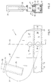
- Figure 1 shows the device according to the invention an adjusting member 1 which is slidable and clampable on a rail 10, there is.
- the rail 10 has the shape of a box profile with a bottom 12 and one longitudinally open top, of which the longitudinal opening of two horizontal, facing flanges 11 is limited.
- the rail 10 is shown in FIG Cross section shown.
- the adjusting member 1 consists of a main body 20 with a front 21 and a rear 22 Front 21 is a rectangular box section 24 is attached for receiving a pin 30 on a seat (not shown) stuck. There is a stop 31 on pin 30 attached to support a seat on the box section 24.
- Figure 2 shows a cross section of the device according to the figure 1 along the cross-sectional area II-II through the pins 25 and 26.
- Figure 1 and Figure 2 show the device, the Setting device 1 is unlocked, i.e. not on the box profile 10 is clamped and therefore freely movable along the box section 10. In this state is the distance between the terminal blocks 27 and 28 is greater than the thickness of the flanges 11.
- the rear end 22 of the main body 20 has a stop surface 23 which in the unlocked Condition against the bottom 12 of the box section 10 can and thus forms a sliding surface when Move the adjuster 1 to the seat in one to set a different stand.
- the stop surface 23 also serves to ensure that the main body 20 does not continue after can tilt to the right so that the adjusting member 1 is adjustable remains.
- Figure 4 shows the locked state of Figure 3 in Cross section along the average area IV-IV through the Pins 25 and 26 in Figure 3.
- the clamping blocks 27 and 28 are clamped by the own weight of main body 20, the one Moment around pins 25 and 26.
- weight of the seat on the pin 30 in the vertical profile 24 takes that Clamping moment too and the weight of the user in the seat will increase the clamping torque even further, so that no danger of unlocking or during use Displacement of the adjusting member 1 along the rail 10 consists.
- the front part needs to unlock the adjusting element 1 21 of the main body 20 only to be lifted.
- Clamping blocks 27, 28 extend on the side cylindrical part that rotates in the holes in the Main body 20 is included.
- the pins 25, 26 can then expire.
- the top terminal blocks 27 must fixed together with e.g. a dowel pin but this is not the case with the bottom terminal blocks 28 necessary because these are included in the box profile 10.
- the terminal blocks are preferably made of one wear-resistant plastic, such as nylon.
- the device according to the invention has the advantage that this is simple and robust, and that no adjustment lever is required to operate the facility. Is too no spring necessary to lock the adjustment element, so that there is no risk of spring breakage.
- the facility is to be carried out in such a way that the maximum distance between the terminal blocks 27 and the flanges 11 so small is that a finger of a (child's) hand is never between can be brought so that the facility also Child-safe is what is especially great for pedal cars Importance is.
Abstract
Description
Claims (14)
- Einrichtung für das Einstellen der Stelle eines Sitzes in ein Fahrzeug, insbesondere in ein Tretauto, wobei der Sitz stufenlos durch Klemmittel auf einer Führung einzustellen ist, dadurch gekennzeichnet, daß die Klemmittel mit Hilfe von der Schwerkraft auf die Führung festklemmbar sind.
- Einrichtung für das Einstellen der Stelle eines Sitzes in ein Fahrzeug, insbesondere in ein Tretauto, wobei der Sitz stufenlos durch Klemmittel auf einer Führung einzustellen ist, dadurch gekennzeichnet, daß die Klemmittel durch Drehung in der Vertikalebene auf die Führung festklemmbar sind.
- Einrichtung gemäß Anspruch 2, wobei die Klemmittel mit Hilfe von der Schwerkraft auf die Führung festklemmbar sind.
- Einrichtung gemäß Anspruch 1, 2 oder 3, wobei die Führung eine Schiene ist, worauf die Klemmittel festzuklemmen sind.
- Einrichtung gemäß Anspruch 4, wobei die Klemmittel auch eine Führungsfunktion haben.
- Einrichtung gemäß Anspruch 4 oder 5, wobei die Klemmittel mindestens zwei längliche Klemmblöcke umfassen, die beiderseitig von einem Klemmstreifen der Schiene zu der Schiene parallel verlaufen, um den Klemmstreifen zwischen sich zu klemmen.
- Einrichtung gemäß Anspruch 6, wobei die Einrichtung einen Hauptkörper umfäßt, der von zwei parallel frei rotierbaren Stiften an den die Klemmblöcke hauptsächlich halbwegs ihrer Länge angeordnet sind, versehen ist, um bei Verschwenken des Hauptkörpers den Abstand zwischen den parallel verlaufenden Klemmblöcken zu ändern.
- Einrichtung gemäß Anspruch 7, wobei die Schiene ein Kastenprofil ist mit einer teilweise offenen Oberseite mit mindestens einem Klemmstreifen für die Klemmblöcke, wovon mindestens ein in dem Kastenprofil beweglich ist und ein oben dem Kastenprofil beweglich ist, wobei der Hauptkörper teilweise im Kastenprofil aufgenommen ist.
- Einrichtung gemäß Anspruch 8, wobei beiderseitig von der Öffnung in der Oberseite des Kastenprofils ein Klemmstreifen vorhanden ist und an beiden Seiten des Hauptkörpers zwei Klemmblöcke vorhanden sind um auf beide Klemmstreifen zu klemmen.
- Einrichtung gemäß Anspruch 8 oder 9, wobei der Hauptkörper im Kastenprofil eine Anschlagfläche besitzt, die als Lauffläche beim Verstellen des Sitzes dient.
- Einrichtung gemäß Anspruch 7, 8, 9 oder 10, wobei der Schwerpunkt des Hauptkörpers, des Hauptkörpers plus Sitzes und des Hauptkörpers plus Sitzes plus Benutzers in horizontaler Richtung auf Abstand von den Stiften mit Klemmblöcken liegt, um eine gute Klemmung zu gewährleisten.
- Einrichtung gemäß Anspruch 7,8, 9, 10 oder 11, wobei am Hauptkörper eine Hülse für das Aufnehmen eines Stiftes an einen abmontierbaren Sitz befestigt ist.
- Einrichtung für das Verstellen des Abstandes zwischen Sitz und Pedale eines Tretautos, wobei in der Längsrichtung ein Kastenprofil angebracht worden ist, mit einer teilweise offenen Oberseite und beiderseitig von der Öffnung nach einander zugerichteten Klemmstreifen, wobei die Unterseite eines Hauptkörpers der Einrichtung in das Kastenprofil steckt und da von einem ersten frei drehbaren Stift mit beiderseitig vom Hauptkörper an dem Stift angeordneten untersten Klemmstrips im Kastenprofil versehen ist, und ober dem ersten Stift einen zweiten frei im Hauptkörper drehbaren Stift mit daran angeordneten obersten Klemmstrips, um beim Verschwenken des Hauptkörpers, an den der Sitz zu befestigen ist, die Klemmstreifen zwischen den untersten und obersten Klemmstrips zu klemmen um den Sitz zu verriegeln oder zu entriegeln.
- Einrichtung für das Einstellen der Sitzstelle in ein Fahrzeug von einer oder mehreren kennzeichnenden Maßnahmen aus der Beschreibung und/oder Zeichnung versehen.
Priority Applications (1)
| Application Number | Priority Date | Filing Date | Title |
|---|---|---|---|
| EP99203793A EP0982177A1 (de) | 1997-09-30 | 1998-09-30 | Einrichtung für das Einstellen der Stelle eines Sitzes in ein Fahrzeug |
Applications Claiming Priority (2)
| Application Number | Priority Date | Filing Date | Title |
|---|---|---|---|
| NL1007180A NL1007180C2 (nl) | 1997-09-30 | 1997-09-30 | Inrichting voor het instellen van de plaats van een stoel in een voertuig. |
| NL1007180 | 1997-09-30 |
Related Child Applications (1)
| Application Number | Title | Priority Date | Filing Date |
|---|---|---|---|
| EP99203793A Division EP0982177A1 (de) | 1997-09-30 | 1998-09-30 | Einrichtung für das Einstellen der Stelle eines Sitzes in ein Fahrzeug |
Publications (2)
| Publication Number | Publication Date |
|---|---|
| EP0904975A1 true EP0904975A1 (de) | 1999-03-31 |
| EP0904975B1 EP0904975B1 (de) | 2002-03-13 |
Family
ID=19765774
Family Applications (2)
| Application Number | Title | Priority Date | Filing Date |
|---|---|---|---|
| EP98203282A Expired - Lifetime EP0904975B1 (de) | 1997-09-30 | 1998-09-30 | Einrichtung für das Einstellen der Stelle eines Sitzes in ein Fahrzeug |
| EP99203793A Withdrawn EP0982177A1 (de) | 1997-09-30 | 1998-09-30 | Einrichtung für das Einstellen der Stelle eines Sitzes in ein Fahrzeug |
Family Applications After (1)
| Application Number | Title | Priority Date | Filing Date |
|---|---|---|---|
| EP99203793A Withdrawn EP0982177A1 (de) | 1997-09-30 | 1998-09-30 | Einrichtung für das Einstellen der Stelle eines Sitzes in ein Fahrzeug |
Country Status (4)
| Country | Link |
|---|---|
| EP (2) | EP0904975B1 (de) |
| AT (1) | ATE214343T1 (de) |
| DE (1) | DE59803318D1 (de) |
| NL (1) | NL1007180C2 (de) |
Citations (3)
| Publication number | Priority date | Publication date | Assignee | Title |
|---|---|---|---|---|
| US3486204A (en) * | 1967-07-26 | 1969-12-30 | Mc Donnell Douglas Corp | Seat pallet latch |
| DE9314844U1 (de) * | 1993-10-01 | 1994-02-03 | Westfalia Werke Knoebel | Vorrichtung zur Befestigung von Sitzgestellen am Boden eines Fahrzeugs |
| FR2728860A1 (fr) * | 1994-12-30 | 1996-07-05 | Renault | Plancher de vehicule automobile |
Family Cites Families (1)
| Publication number | Priority date | Publication date | Assignee | Title |
|---|---|---|---|---|
| US5509678A (en) | 1994-01-28 | 1996-04-23 | Ullman; David G. | Recumbent bicycle |
-
1997
- 1997-09-30 NL NL1007180A patent/NL1007180C2/nl not_active IP Right Cessation
-
1998
- 1998-09-30 AT AT98203282T patent/ATE214343T1/de not_active IP Right Cessation
- 1998-09-30 DE DE59803318T patent/DE59803318D1/de not_active Expired - Fee Related
- 1998-09-30 EP EP98203282A patent/EP0904975B1/de not_active Expired - Lifetime
- 1998-09-30 EP EP99203793A patent/EP0982177A1/de not_active Withdrawn
Patent Citations (3)
| Publication number | Priority date | Publication date | Assignee | Title |
|---|---|---|---|---|
| US3486204A (en) * | 1967-07-26 | 1969-12-30 | Mc Donnell Douglas Corp | Seat pallet latch |
| DE9314844U1 (de) * | 1993-10-01 | 1994-02-03 | Westfalia Werke Knoebel | Vorrichtung zur Befestigung von Sitzgestellen am Boden eines Fahrzeugs |
| FR2728860A1 (fr) * | 1994-12-30 | 1996-07-05 | Renault | Plancher de vehicule automobile |
Also Published As
| Publication number | Publication date |
|---|---|
| DE59803318D1 (de) | 2002-04-18 |
| NL1007180C2 (nl) | 1999-01-21 |
| ATE214343T1 (de) | 2002-03-15 |
| EP0904975B1 (de) | 2002-03-13 |
| EP0982177A1 (de) | 2000-03-01 |
Similar Documents
| Publication | Publication Date | Title |
|---|---|---|
| DE2941303C2 (de) | Vorrichtung zum Einstellen des Neigungswinkels der Lenksäule einer Kraftfahrzeuglenkung | |
| EP0670123A1 (de) | Höhenverstellbarer Arbeitstisch | |
| DE2513188C2 (de) | Anordnung eines Fersenhalters einer Skibindung und einer Skibremse für einen vom Skistiefel losgelösten Ski auf einer auf der Skioberfläche befestigten Bodenplatte | |
| DE4100327C2 (de) | Vorrichtung zum Befestigen einer Skibindung auf einem Ski | |
| DE4106401C2 (de) | Snowboard-Bindung | |
| EP2987538B1 (de) | Vordereinheit für eine skibindung und system, bestehend aus einer vordereinheit und einer hintereinheit | |
| DE2940463A1 (de) | In sitzlaengsrichtung verstellbarer automobilsitz | |
| DE4139783C2 (de) | Sitzanordnung für ein Kraftfahrzeug | |
| DD215282A5 (de) | Sitzgestell mit hangausgleich fuer fahrzeuge, insbesondere ackerschlepper | |
| DE3619944A1 (de) | Der rueckenlehne eines kraftfahrzeugsitzes zugeordnete armlehne | |
| DE19904224C1 (de) | Verstellbares Sitzuntergestell für einen Fahrzeugsitz | |
| EP1599370B1 (de) | Vorrichtung zum befestigen eines gurtschlosses eines sicherheitsgurtes an einem fahrzeugsitz | |
| DE1559829B1 (de) | Laufrollenblock für schiebetüren oder schiebefenster | |
| DE3817977C2 (de) | ||
| DE60020761T2 (de) | Träger für Fahrzeugsitze | |
| EP0433317B1 (de) | Kindersicherheitssitz | |
| DE19626641A1 (de) | Kindersitz | |
| EP0904975B1 (de) | Einrichtung für das Einstellen der Stelle eines Sitzes in ein Fahrzeug | |
| EP0217467A1 (de) | Treppe | |
| DE8231574U1 (de) | Fahrzeugsitz mit schwenkbarer ruecklehne | |
| DE3134608C2 (de) | ||
| DE19816576C2 (de) | Fahrwerk, insbesondere für Hubwerke | |
| DE3822453C2 (de) | Verstellschienenanordnung, insbesondere für PKW-Sitze | |
| DE3543514A1 (de) | Vorrichtung zur befestigung von dachlasten | |
| DE3929001A1 (de) | Einrichtung zur hoehenverstellung mit stetigem gewichtsausgleich |
Legal Events
| Date | Code | Title | Description |
|---|---|---|---|
| PUAI | Public reference made under article 153(3) epc to a published international application that has entered the european phase |
Free format text: ORIGINAL CODE: 0009012 |
|
| AK | Designated contracting states |
Kind code of ref document: A1 Designated state(s): AT BE CH DE DK FR GB LI NL |
|
| AX | Request for extension of the european patent |
Free format text: AL;LT;LV;MK;RO;SI |
|
| 17P | Request for examination filed |
Effective date: 19990928 |
|
| AKX | Designation fees paid |
Free format text: AT BE CH DE DK FR GB LI NL |
|
| 17Q | First examination report despatched |
Effective date: 20000711 |
|
| GRAG | Despatch of communication of intention to grant |
Free format text: ORIGINAL CODE: EPIDOS AGRA |
|
| GRAG | Despatch of communication of intention to grant |
Free format text: ORIGINAL CODE: EPIDOS AGRA |
|
| GRAH | Despatch of communication of intention to grant a patent |
Free format text: ORIGINAL CODE: EPIDOS IGRA |
|
| GRAH | Despatch of communication of intention to grant a patent |
Free format text: ORIGINAL CODE: EPIDOS IGRA |
|
| REG | Reference to a national code |
Ref country code: GB Ref legal event code: IF02 |
|
| GRAA | (expected) grant |
Free format text: ORIGINAL CODE: 0009210 |
|
| AK | Designated contracting states |
Kind code of ref document: B1 Designated state(s): AT BE CH DE DK FR GB LI NL |
|
| PG25 | Lapsed in a contracting state [announced via postgrant information from national office to epo] |
Ref country code: NL Free format text: LAPSE BECAUSE OF FAILURE TO SUBMIT A TRANSLATION OF THE DESCRIPTION OR TO PAY THE FEE WITHIN THE PRESCRIBED TIME-LIMIT Effective date: 20020313 Ref country code: GB Free format text: LAPSE BECAUSE OF FAILURE TO SUBMIT A TRANSLATION OF THE DESCRIPTION OR TO PAY THE FEE WITHIN THE PRESCRIBED TIME-LIMIT Effective date: 20020313 Ref country code: FR Free format text: LAPSE BECAUSE OF FAILURE TO SUBMIT A TRANSLATION OF THE DESCRIPTION OR TO PAY THE FEE WITHIN THE PRESCRIBED TIME-LIMIT Effective date: 20020313 |
|
| REF | Corresponds to: |
Ref document number: 214343 Country of ref document: AT Date of ref document: 20020315 Kind code of ref document: T |
|
| REG | Reference to a national code |
Ref country code: CH Ref legal event code: EP |
|
| REF | Corresponds to: |
Ref document number: 59803318 Country of ref document: DE Date of ref document: 20020418 |
|
| PG25 | Lapsed in a contracting state [announced via postgrant information from national office to epo] |
Ref country code: DK Free format text: LAPSE BECAUSE OF FAILURE TO SUBMIT A TRANSLATION OF THE DESCRIPTION OR TO PAY THE FEE WITHIN THE PRESCRIBED TIME-LIMIT Effective date: 20020613 |
|
| NLV1 | Nl: lapsed or annulled due to failure to fulfill the requirements of art. 29p and 29m of the patents act | ||
| GBV | Gb: ep patent (uk) treated as always having been void in accordance with gb section 77(7)/1977 [no translation filed] |
Effective date: 20020313 |
|
| PG25 | Lapsed in a contracting state [announced via postgrant information from national office to epo] |
Ref country code: LI Free format text: LAPSE BECAUSE OF NON-PAYMENT OF DUE FEES Effective date: 20020930 Ref country code: CH Free format text: LAPSE BECAUSE OF NON-PAYMENT OF DUE FEES Effective date: 20020930 Ref country code: BE Free format text: LAPSE BECAUSE OF NON-PAYMENT OF DUE FEES Effective date: 20020930 Ref country code: AT Free format text: LAPSE BECAUSE OF NON-PAYMENT OF DUE FEES Effective date: 20020930 |
|
| EN | Fr: translation not filed | ||
| PLBE | No opposition filed within time limit |
Free format text: ORIGINAL CODE: 0009261 |
|
| STAA | Information on the status of an ep patent application or granted ep patent |
Free format text: STATUS: NO OPPOSITION FILED WITHIN TIME LIMIT |
|
| 26N | No opposition filed |
Effective date: 20021216 |
|
| BERE | Be: lapsed |
Owner name: *VAN EE TEUNIS KAREL Effective date: 20020930 |
|
| PG25 | Lapsed in a contracting state [announced via postgrant information from national office to epo] |
Ref country code: DE Free format text: LAPSE BECAUSE OF NON-PAYMENT OF DUE FEES Effective date: 20030401 |
|
| REG | Reference to a national code |
Ref country code: CH Ref legal event code: PL |