EP0904970A2 - Système de régulation de vitesse moteur avec commande de vitesse de croisière optionelle - Google Patents
Système de régulation de vitesse moteur avec commande de vitesse de croisière optionelle Download PDFInfo
- Publication number
- EP0904970A2 EP0904970A2 EP98306638A EP98306638A EP0904970A2 EP 0904970 A2 EP0904970 A2 EP 0904970A2 EP 98306638 A EP98306638 A EP 98306638A EP 98306638 A EP98306638 A EP 98306638A EP 0904970 A2 EP0904970 A2 EP 0904970A2
- Authority
- EP
- European Patent Office
- Prior art keywords
- speed
- cruise
- signal
- engine
- idle
- Prior art date
- Legal status (The legal status is an assumption and is not a legal conclusion. Google has not performed a legal analysis and makes no representation as to the accuracy of the status listed.)
- Granted
Links
Images

Classifications
-
- B—PERFORMING OPERATIONS; TRANSPORTING
- B60—VEHICLES IN GENERAL
- B60K—ARRANGEMENT OR MOUNTING OF PROPULSION UNITS OR OF TRANSMISSIONS IN VEHICLES; ARRANGEMENT OR MOUNTING OF PLURAL DIVERSE PRIME-MOVERS IN VEHICLES; AUXILIARY DRIVES FOR VEHICLES; INSTRUMENTATION OR DASHBOARDS FOR VEHICLES; ARRANGEMENTS IN CONNECTION WITH COOLING, AIR INTAKE, GAS EXHAUST OR FUEL SUPPLY OF PROPULSION UNITS IN VEHICLES
- B60K31/00—Vehicle fittings, acting on a single sub-unit only, for automatically controlling vehicle speed, i.e. preventing speed from exceeding an arbitrarily established velocity or maintaining speed at a particular velocity, as selected by the vehicle operator
- B60K31/02—Vehicle fittings, acting on a single sub-unit only, for automatically controlling vehicle speed, i.e. preventing speed from exceeding an arbitrarily established velocity or maintaining speed at a particular velocity, as selected by the vehicle operator including electrically actuated servomechanism
- B60K31/04—Vehicle fittings, acting on a single sub-unit only, for automatically controlling vehicle speed, i.e. preventing speed from exceeding an arbitrarily established velocity or maintaining speed at a particular velocity, as selected by the vehicle operator including electrically actuated servomechanism and means for comparing one electrical quantity, e.g. voltage, pulse, waveform, flux, or the like, with another quantity of a like kind, which comparison means is involved in the development of an electrical signal which is fed into the controlling means
- B60K31/042—Vehicle fittings, acting on a single sub-unit only, for automatically controlling vehicle speed, i.e. preventing speed from exceeding an arbitrarily established velocity or maintaining speed at a particular velocity, as selected by the vehicle operator including electrically actuated servomechanism and means for comparing one electrical quantity, e.g. voltage, pulse, waveform, flux, or the like, with another quantity of a like kind, which comparison means is involved in the development of an electrical signal which is fed into the controlling means where at least one electrical quantity is set by the vehicle operator
- B60K31/045—Vehicle fittings, acting on a single sub-unit only, for automatically controlling vehicle speed, i.e. preventing speed from exceeding an arbitrarily established velocity or maintaining speed at a particular velocity, as selected by the vehicle operator including electrically actuated servomechanism and means for comparing one electrical quantity, e.g. voltage, pulse, waveform, flux, or the like, with another quantity of a like kind, which comparison means is involved in the development of an electrical signal which is fed into the controlling means where at least one electrical quantity is set by the vehicle operator in a memory, e.g. a capacitor
- B60K31/047—Vehicle fittings, acting on a single sub-unit only, for automatically controlling vehicle speed, i.e. preventing speed from exceeding an arbitrarily established velocity or maintaining speed at a particular velocity, as selected by the vehicle operator including electrically actuated servomechanism and means for comparing one electrical quantity, e.g. voltage, pulse, waveform, flux, or the like, with another quantity of a like kind, which comparison means is involved in the development of an electrical signal which is fed into the controlling means where at least one electrical quantity is set by the vehicle operator in a memory, e.g. a capacitor the memory being digital
-
- B—PERFORMING OPERATIONS; TRANSPORTING
- B60—VEHICLES IN GENERAL
- B60W—CONJOINT CONTROL OF VEHICLE SUB-UNITS OF DIFFERENT TYPE OR DIFFERENT FUNCTION; CONTROL SYSTEMS SPECIALLY ADAPTED FOR HYBRID VEHICLES; ROAD VEHICLE DRIVE CONTROL SYSTEMS FOR PURPOSES NOT RELATED TO THE CONTROL OF A PARTICULAR SUB-UNIT
- B60W2510/00—Input parameters relating to a particular sub-units
- B60W2510/10—Change speed gearings
- B60W2510/1005—Transmission ratio engaged
-
- B—PERFORMING OPERATIONS; TRANSPORTING
- B60—VEHICLES IN GENERAL
- B60W—CONJOINT CONTROL OF VEHICLE SUB-UNITS OF DIFFERENT TYPE OR DIFFERENT FUNCTION; CONTROL SYSTEMS SPECIALLY ADAPTED FOR HYBRID VEHICLES; ROAD VEHICLE DRIVE CONTROL SYSTEMS FOR PURPOSES NOT RELATED TO THE CONTROL OF A PARTICULAR SUB-UNIT
- B60W2710/00—Output or target parameters relating to a particular sub-units
- B60W2710/06—Combustion engines, Gas turbines
- B60W2710/0644—Engine speed
- B60W2710/065—Idle condition
-
- F—MECHANICAL ENGINEERING; LIGHTING; HEATING; WEAPONS; BLASTING
- F16—ENGINEERING ELEMENTS AND UNITS; GENERAL MEASURES FOR PRODUCING AND MAINTAINING EFFECTIVE FUNCTIONING OF MACHINES OR INSTALLATIONS; THERMAL INSULATION IN GENERAL
- F16H—GEARING
- F16H63/00—Control outputs from the control unit to change-speed- or reversing-gearings for conveying rotary motion or to other devices than the final output mechanism
- F16H63/40—Control outputs from the control unit to change-speed- or reversing-gearings for conveying rotary motion or to other devices than the final output mechanism comprising signals other than signals for actuating the final output mechanisms
- F16H63/50—Signals to an engine or motor
Definitions
- a signal from vehicle speed sensor which may be the same as the speedometer sensor, as a reference signal which is compared with a second reference signal which is held at a steady value following activation of the cruise control by the driver.
- the speed signal will in general vary as the vehicle is being driven, for example owing to changes in road gradient, headwind, or the demands placed upon the engine power output from accessories, such as a vehicle air conditioning unit.
- the apparatus may comprise a sensor arrangement to measure the rotational speed of the drive shaft, or equivalently any other part of a vehicle drive train between the transmission and a road-going wheel, and so produce the vehicle speed signal.
- the engine management system may then comprise a memory that stores data representative of a drive shaft/axle ratio and of a tire size. When such data are recalled from memory, the speed signal representative of actual vehicle speed may be calculated from the drive shaft rotational speed, axle ratio and tire size.
- An advantage of this approach is that there may be no need to provide an additional engine speed sensor, as such sensors are usually needed for other purposes, for example in scheduling engine spark or injection events.
- One such type of sensor detects the presence of teeth around the circumference of a toothed wheel on the engine crankshaft. Such a sensor may have 36 teeth around the circumference in order to give an engine speed measurement accurate enough to schedule a spark or injection event with a few degrees of engine revolution. Whilst such accuracy is not necessary to achieve steady cruise control, the use of such a sensor to measure engine speed, permits an improvement in accuracy and response time compared with sensors based on detecting eddy currents generated by rotating magnets, such as those used in speedometers.
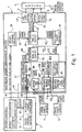
- an electronic engine management (EEM) system 1 receives inputs from driver controls 2, a crank shaft sensor 4, a drive shaft sensor, and provides outputs 8 to an internal combustion engine 9, for example, in a motor car (not shown).
- the engine 9 will, in general, provide other signals, shown by the dashed line 10, representative of various engine operating parameters, such as temperature, oil pressure, battery voltage, etc, which the EEM system 1 may use as inputs in order to generate the desired outputs 8.
- crankshaft sensor 4 is a conventional toothed wheel on the crankshaft, which provides an engine speed signal 5 in the form of thirty-six pulses for each revolution of the engine 9.
- a drive shaft sensor 6, also not shown, comprises a cable with a rotatable core which is driven by the rotation of the propeller or drive shaft, and which in turn rotates a magnet.
- a Hall effect sensor is then used to measure the rotating magnetic field and to generate a drive shaft speed signal 7 in the form of an analog voltage which is then a measure of the rate of rotation of the cable and drive shaft.
- the cruise control switches and circuitry 14 will most commonly be provided on a steering column stalk or on the steering wheel itself (not shown). When the cruise control is set, a non-zero voltage is provided as a target cruise speed signal 20 by the cruise switches and circuitry 14 to the EEM system.
- the EEM system may be used in a vehicle that does not have cruise control, in which case the target cruise speed signal is made zero by a pull down resistance internal to the cruise speed controller 22.
- the EEM system detects 102 the non-zero target speed signal 20, and then in a cruise speed controller 22 calculates 104 first a vehicle speed 104 according to the drive shaft speed signal 7.
- a gearing ratio 26 may then be calculated 108 from the vehicle speed and the engine speed signal 5, by dividing the engine speed by the vehicle speed.
- the cruise speed controller 22 then calculates 110 as an output a cruise signal 28 by multiplying the target cruise speed signal 20 by the gearing ratio 26.
- the EEM system will normally have integrated with the system, circuitry 30 necessary to control the idle speed. This will have the usual features associated with such control, for example with a faster idle speed during warm up of the engine 9.
- This idle speed circuitry 30 provides an idle signal 32, which is then compared with the cruise signal 28 in a first 'max-output' comparator 34.
- the first comparator 34 selects the signal representative of the greater engine speed and provides this as an input 112 to a combined idle-cruise speed controller 36.
- the target speed signal 20 will be zero, as will be the cruise signal 28, and so in this instance, the first comparator will pass 114 just the idle signal 32 as the input to the combined idle-cruise controller 36.
- the accelerator pedal setting signal 18 is being passed continuously to a driver demand controller 38.
- the driver demand controller 38 and the idle-cruise controller each produce an output 40,42 representative of a target engine speed, and these are each passed to a second 'max-output' comparator 44 which selects the input representative of the larger target engine speed as a control output 46 for regulating the engine speed.
- the control output 46 may then be used, optionally with other signals such as those from engine operating condition sensors 10, by the EEM system 1 to generate the signals needed to run a fuel pump control 48, an injector control 50, and in the case of a gasoline engine, also the spark scheduling 52.
- the apparatus and method described above allow the elimination of the need to have an actuator to physically move the accelerator pedal.
- the cruise speed controller may then be implemented in electronics and software, for example within an EEM system module - this allows a reduction in manufacturing cost.
- the separation of the cruise speed controller from the driver demand controller also simplifies the design and programming of the driver demand controller: the so-called mapping of the accelerator pedal setting and other engine parameters, with a desired control output 46.
- the use of an engine speed signal 5 from the crankshaft improves the response of the cruise control feedback loop to follow changes in vehicle or engine speed and keep the vehicle speed steady.
- the use of a combined idle-cruise speed controller 36 taking as its input either a cruise signal or an idle signal allows the EEM system to be used in vehicles both with and without cruise control.
Landscapes
- Engineering & Computer Science (AREA)
- Chemical & Material Sciences (AREA)
- Combustion & Propulsion (AREA)
- Transportation (AREA)
- Mechanical Engineering (AREA)
- Controls For Constant Speed Travelling (AREA)
- Control Of Vehicle Engines Or Engines For Specific Uses (AREA)
Applications Claiming Priority (2)
| Application Number | Priority Date | Filing Date | Title |
|---|---|---|---|
| GB9720776A GB2329725A (en) | 1997-09-30 | 1997-09-30 | Vehicle cruise control and engine idle control |
| GB9720776 | 1997-09-30 |
Publications (3)
| Publication Number | Publication Date |
|---|---|
| EP0904970A2 true EP0904970A2 (fr) | 1999-03-31 |
| EP0904970A3 EP0904970A3 (fr) | 2000-02-23 |
| EP0904970B1 EP0904970B1 (fr) | 2003-06-25 |
Family
ID=10819852
Family Applications (1)
| Application Number | Title | Priority Date | Filing Date |
|---|---|---|---|
| EP98306638A Expired - Lifetime EP0904970B1 (fr) | 1997-09-30 | 1998-08-19 | Système de régulation de vitesse moteur avec commande de vitesse de croisière optionelle |
Country Status (4)
| Country | Link |
|---|---|
| US (1) | US5961566A (fr) |
| EP (1) | EP0904970B1 (fr) |
| DE (1) | DE69815775T2 (fr) |
| GB (1) | GB2329725A (fr) |
Cited By (2)
| Publication number | Priority date | Publication date | Assignee | Title |
|---|---|---|---|---|
| WO2001079016A1 (fr) * | 2000-04-17 | 2001-10-25 | Robert Bosch Gmbh | Procede et dispositif permettant de regler un rapport de transmission dans une automobile, au moyen d'un regulateur de vitesse adaptatif |
| EP1541405A1 (fr) * | 2003-12-09 | 2005-06-15 | Textron Inc. | Systeme de commande d'un moteur |
Families Citing this family (18)
| Publication number | Priority date | Publication date | Assignee | Title |
|---|---|---|---|---|
| DE19803387C1 (de) * | 1998-01-29 | 1999-03-18 | Daimler Benz Ag | Verfahren zur Einstellung der Ausgangsleistung einer Brennkraftmaschine |
| US6167979B1 (en) * | 1998-05-20 | 2001-01-02 | Cummins Engine Company, Inc. | Dynamic speed governing of a vehicle |
| US6308124B1 (en) * | 1998-11-16 | 2001-10-23 | Cummins Engine Company, Inc. | System for determining an equivalent throttle valve for controlling automatic transmission shift points |
| JP3726537B2 (ja) * | 1999-03-16 | 2005-12-14 | 日産自動車株式会社 | 車両の駆動力制御装置 |
| JP2000320658A (ja) | 1999-05-14 | 2000-11-24 | Honda Motor Co Ltd | 車両の速度制御装置 |
| US6405587B1 (en) * | 2000-05-08 | 2002-06-18 | General Motors Corporation | System and method of controlling the coastdown of a vehicle |
| US6920865B2 (en) | 2002-01-29 | 2005-07-26 | Daimlerchrysler Corporation | Mechatronic vehicle powertrain control system |
| US6863047B2 (en) * | 2002-07-22 | 2005-03-08 | Siemens Vdo Automotive Corporation | Method of controlling engine speed during performance shift |
| US20040238250A1 (en) * | 2003-05-27 | 2004-12-02 | David Young | Motorcycle cruise control installation kit |
| JP4655723B2 (ja) * | 2005-03-31 | 2011-03-23 | トヨタ自動車株式会社 | 車両およびその制御方法 |
| US7263429B2 (en) * | 2005-08-11 | 2007-08-28 | Gm Global Technology Operations, Inc. | Cruise idle speed control to enhance low speed and light throttle drivability |
| US8041485B2 (en) * | 2006-12-31 | 2011-10-18 | Caterpillar Inc. | System and method for operating a machine |
| DE102007055931A1 (de) | 2007-12-28 | 2009-07-02 | Ecomotec Gmbh | Verfahren sowie Vorrichtung zum Betreiben eines Verbrennungsmotors eines Fahrzeugs |
| US8816804B2 (en) * | 2011-09-22 | 2014-08-26 | Tyco Electronics Corporation | Switch assembly and system |
| US20140083392A1 (en) * | 2012-09-27 | 2014-03-27 | International Engine Intellectual Property Company, Llc | Methods for controlling engine idle speed |
| US20140083393A1 (en) * | 2012-09-27 | 2014-03-27 | International Engine Intellectual Property Company, Llc | Methods for controlling engine idle speed |
| US20140358400A1 (en) * | 2013-05-29 | 2014-12-04 | GM Global Technology Operations LLC | System and method for controlling a powertrain system to perform exhaust braking |
| JP6286965B2 (ja) * | 2013-09-18 | 2018-03-07 | 株式会社豊田自動織機 | 産業車両の車速制御装置 |
Citations (1)
| Publication number | Priority date | Publication date | Assignee | Title |
|---|---|---|---|---|
| EP0353072A1 (fr) | 1988-07-27 | 1990-01-31 | Honda Giken Kogyo Kabushiki Kaisha | Système de commande du papillon du moteur à combustion d'un véhicule automobile |
Family Cites Families (3)
| Publication number | Priority date | Publication date | Assignee | Title |
|---|---|---|---|---|
| DE2701567C2 (de) * | 1977-01-15 | 1987-03-26 | Robert Bosch Gmbh, 7000 Stuttgart | Geschwindigkeitssteuereinrichtung für Fahrzeuge |
| JPH03217337A (ja) * | 1990-01-20 | 1991-09-25 | Mitsubishi Electric Corp | 車両用定速走行装置 |
| US5624005A (en) * | 1994-05-23 | 1997-04-29 | Nippondenso Co., Ltd. | Running speed control device for a vehicle |
-
1997
- 1997-09-30 GB GB9720776A patent/GB2329725A/en not_active Withdrawn
-
1998
- 1998-08-19 EP EP98306638A patent/EP0904970B1/fr not_active Expired - Lifetime
- 1998-08-19 DE DE69815775T patent/DE69815775T2/de not_active Expired - Fee Related
- 1998-09-25 US US09/160,686 patent/US5961566A/en not_active Expired - Fee Related
Patent Citations (1)
| Publication number | Priority date | Publication date | Assignee | Title |
|---|---|---|---|---|
| EP0353072A1 (fr) | 1988-07-27 | 1990-01-31 | Honda Giken Kogyo Kabushiki Kaisha | Système de commande du papillon du moteur à combustion d'un véhicule automobile |
Cited By (5)
| Publication number | Priority date | Publication date | Assignee | Title |
|---|---|---|---|---|
| WO2001079016A1 (fr) * | 2000-04-17 | 2001-10-25 | Robert Bosch Gmbh | Procede et dispositif permettant de regler un rapport de transmission dans une automobile, au moyen d'un regulateur de vitesse adaptatif |
| EP1541405A1 (fr) * | 2003-12-09 | 2005-06-15 | Textron Inc. | Systeme de commande d'un moteur |
| US7111699B2 (en) | 2003-12-09 | 2006-09-26 | Textron Inc. | Engine governor system |
| KR100723443B1 (ko) * | 2003-12-09 | 2007-05-30 | 텍스트론 인크. | 엔진 조속 시스템 |
| US7303036B2 (en) | 2003-12-09 | 2007-12-04 | Textron Inc. | Engine governor system |
Also Published As
| Publication number | Publication date |
|---|---|
| EP0904970B1 (fr) | 2003-06-25 |
| GB9720776D0 (en) | 1997-12-03 |
| DE69815775D1 (de) | 2003-07-31 |
| EP0904970A3 (fr) | 2000-02-23 |
| GB2329725A (en) | 1999-03-31 |
| US5961566A (en) | 1999-10-05 |
| DE69815775T2 (de) | 2004-05-19 |
| GB2329725A8 (en) | 2001-02-14 |
Similar Documents
| Publication | Publication Date | Title |
|---|---|---|
| EP0904970B1 (fr) | Système de régulation de vitesse moteur avec commande de vitesse de croisière optionelle | |
| JP3415863B2 (ja) | 車両の駆動ユニットの出力を制御する装置 | |
| US5078109A (en) | Engine output controlling method | |
| US5245966A (en) | Control system for a drive unit in motor vehicle | |
| CA1213654A (fr) | Regulateur de marche pour moteur thermique | |
| EP0247626B1 (fr) | Système et méthode de commande électronique de moteur à combustion interne | |
| US9719443B2 (en) | Vehicle control system and vehicle control method | |
| JPH01177431A (ja) | 内燃機関の電子スロツトル制御装置 | |
| US5899830A (en) | Electronically-controlled throttle system | |
| US6167979B1 (en) | Dynamic speed governing of a vehicle | |
| US5365903A (en) | Engine idling speed control apparatus | |
| EP1323564B1 (fr) | Système de réglage pour véhicule hybride | |
| US6411882B1 (en) | Drive-by-wire vehicle engine output control system | |
| US6847877B2 (en) | Method and arrangement for controlling a drive unit | |
| US5375574A (en) | Engine idling speed control apparatus | |
| US5269272A (en) | Engine idling speed control apparatus | |
| WO1999064265A1 (fr) | Procede et dispositif destines a la regulation de la vitesse | |
| JPH0326840A (ja) | 自動車の運転パラメータを制御する方法及び装置 | |
| JPH0861129A (ja) | 内燃機関を制御するための方法及び装置 | |
| US5642708A (en) | Method of modifying the motion of an output-varying control element | |
| JP3111122B2 (ja) | 内燃エンジンの吸気絞り弁制御装置 | |
| US7288047B1 (en) | Engine and transmission control system and method for a motorized vehicle | |
| JPH0664460A (ja) | 定速走行制御装置 | |
| KR100188583B1 (ko) | 자동차 엔진의 기본분사량 결정방법 | |
| Maynard | A new electronically controlled injection pump for diesels |
Legal Events
| Date | Code | Title | Description |
|---|---|---|---|
| PUAI | Public reference made under article 153(3) epc to a published international application that has entered the european phase |
Free format text: ORIGINAL CODE: 0009012 |
|
| AK | Designated contracting states |
Kind code of ref document: A2 Designated state(s): DE FR GB |
|
| AX | Request for extension of the european patent |
Free format text: AL;LT;LV;MK;RO;SI |
|
| PUAL | Search report despatched |
Free format text: ORIGINAL CODE: 0009013 |
|
| AK | Designated contracting states |
Kind code of ref document: A3 Designated state(s): AT BE CH CY DE DK ES FI FR GB GR IE IT LI LU MC NL PT SE |
|
| AX | Request for extension of the european patent |
Free format text: AL;LT;LV;MK;RO;SI |
|
| 17P | Request for examination filed |
Effective date: 20000714 |
|
| AKX | Designation fees paid |
Free format text: DE FR GB |
|
| GRAH | Despatch of communication of intention to grant a patent |
Free format text: ORIGINAL CODE: EPIDOS IGRA |
|
| GRAH | Despatch of communication of intention to grant a patent |
Free format text: ORIGINAL CODE: EPIDOS IGRA |
|
| GRAA | (expected) grant |
Free format text: ORIGINAL CODE: 0009210 |
|
| AK | Designated contracting states |
Designated state(s): DE FR GB |
|
| REG | Reference to a national code |
Ref country code: GB Ref legal event code: FG4D |
|
| REG | Reference to a national code |
Ref country code: GB Ref legal event code: 732E |
|
| REF | Corresponds to: |
Ref document number: 69815775 Country of ref document: DE Date of ref document: 20030731 Kind code of ref document: P |
|
| ET | Fr: translation filed | ||
| PLBE | No opposition filed within time limit |
Free format text: ORIGINAL CODE: 0009261 |
|
| STAA | Information on the status of an ep patent application or granted ep patent |
Free format text: STATUS: NO OPPOSITION FILED WITHIN TIME LIMIT |
|
| 26N | No opposition filed |
Effective date: 20040326 |
|
| REG | Reference to a national code |
Ref country code: FR Ref legal event code: TP |
|
| PGFP | Annual fee paid to national office [announced via postgrant information from national office to epo] |
Ref country code: GB Payment date: 20050808 Year of fee payment: 8 |
|
| PGFP | Annual fee paid to national office [announced via postgrant information from national office to epo] |
Ref country code: FR Payment date: 20050812 Year of fee payment: 8 Ref country code: DE Payment date: 20050812 Year of fee payment: 8 |
|
| PG25 | Lapsed in a contracting state [announced via postgrant information from national office to epo] |
Ref country code: DE Free format text: LAPSE BECAUSE OF NON-PAYMENT OF DUE FEES Effective date: 20070301 |
|
| GBPC | Gb: european patent ceased through non-payment of renewal fee |
Effective date: 20060819 |
|
| REG | Reference to a national code |
Ref country code: FR Ref legal event code: ST Effective date: 20070430 |
|
| PG25 | Lapsed in a contracting state [announced via postgrant information from national office to epo] |
Ref country code: GB Free format text: LAPSE BECAUSE OF NON-PAYMENT OF DUE FEES Effective date: 20060819 |
|
| PG25 | Lapsed in a contracting state [announced via postgrant information from national office to epo] |
Ref country code: FR Free format text: LAPSE BECAUSE OF NON-PAYMENT OF DUE FEES Effective date: 20060831 |