EP0904956A2 - Baueinheit für Kraftfahrzeugräder - Google Patents
Baueinheit für Kraftfahrzeugräder Download PDFInfo
- Publication number
- EP0904956A2 EP0904956A2 EP98810927A EP98810927A EP0904956A2 EP 0904956 A2 EP0904956 A2 EP 0904956A2 EP 98810927 A EP98810927 A EP 98810927A EP 98810927 A EP98810927 A EP 98810927A EP 0904956 A2 EP0904956 A2 EP 0904956A2
- Authority
- EP
- European Patent Office
- Prior art keywords
- bearing
- wheel
- wheel carrier
- housing
- vehicle wheels
- Prior art date
- Legal status (The legal status is an assumption and is not a legal conclusion. Google has not performed a legal analysis and makes no representation as to the accuracy of the status listed.)
- Granted
Links
Images

Classifications
-
- B—PERFORMING OPERATIONS; TRANSPORTING
- B60—VEHICLES IN GENERAL
- B60B—VEHICLE WHEELS; CASTORS; AXLES FOR WHEELS OR CASTORS; INCREASING WHEEL ADHESION
- B60B27/00—Hubs
- B60B27/0078—Hubs characterised by the fixation of bearings
- B60B27/0084—Hubs characterised by the fixation of bearings caulking to fix inner race
-
- B—PERFORMING OPERATIONS; TRANSPORTING
- B60—VEHICLES IN GENERAL
- B60B—VEHICLE WHEELS; CASTORS; AXLES FOR WHEELS OR CASTORS; INCREASING WHEEL ADHESION
- B60B27/00—Hubs
- B60B27/0005—Hubs with ball bearings
-
- B—PERFORMING OPERATIONS; TRANSPORTING
- B60—VEHICLES IN GENERAL
- B60B—VEHICLE WHEELS; CASTORS; AXLES FOR WHEELS OR CASTORS; INCREASING WHEEL ADHESION
- B60B27/00—Hubs
- B60B27/02—Hubs adapted to be rotatably arranged on axle
-
- F—MECHANICAL ENGINEERING; LIGHTING; HEATING; WEAPONS; BLASTING
- F16—ENGINEERING ELEMENTS AND UNITS; GENERAL MEASURES FOR PRODUCING AND MAINTAINING EFFECTIVE FUNCTIONING OF MACHINES OR INSTALLATIONS; THERMAL INSULATION IN GENERAL
- F16C—SHAFTS; FLEXIBLE SHAFTS; ELEMENTS OR CRANKSHAFT MECHANISMS; ROTARY BODIES OTHER THAN GEARING ELEMENTS; BEARINGS
- F16C35/00—Rigid support of bearing units; Housings, e.g. caps, covers
- F16C35/04—Rigid support of bearing units; Housings, e.g. caps, covers in the case of ball or roller bearings
- F16C35/06—Mounting or dismounting of ball or roller bearings; Fixing them onto shaft or in housing
- F16C35/067—Fixing them in a housing
-
- F—MECHANICAL ENGINEERING; LIGHTING; HEATING; WEAPONS; BLASTING
- F16—ENGINEERING ELEMENTS AND UNITS; GENERAL MEASURES FOR PRODUCING AND MAINTAINING EFFECTIVE FUNCTIONING OF MACHINES OR INSTALLATIONS; THERMAL INSULATION IN GENERAL
- F16C—SHAFTS; FLEXIBLE SHAFTS; ELEMENTS OR CRANKSHAFT MECHANISMS; ROTARY BODIES OTHER THAN GEARING ELEMENTS; BEARINGS
- F16C19/00—Bearings with rolling contact, for exclusively rotary movement
- F16C19/02—Bearings with rolling contact, for exclusively rotary movement with bearing balls essentially of the same size in one or more circular rows
- F16C19/14—Bearings with rolling contact, for exclusively rotary movement with bearing balls essentially of the same size in one or more circular rows for both radial and axial load
- F16C19/18—Bearings with rolling contact, for exclusively rotary movement with bearing balls essentially of the same size in one or more circular rows for both radial and axial load with two or more rows of balls
- F16C19/181—Bearings with rolling contact, for exclusively rotary movement with bearing balls essentially of the same size in one or more circular rows for both radial and axial load with two or more rows of balls with angular contact
- F16C19/183—Bearings with rolling contact, for exclusively rotary movement with bearing balls essentially of the same size in one or more circular rows for both radial and axial load with two or more rows of balls with angular contact with two rows at opposite angles
- F16C19/184—Bearings with rolling contact, for exclusively rotary movement with bearing balls essentially of the same size in one or more circular rows for both radial and axial load with two or more rows of balls with angular contact with two rows at opposite angles in O-arrangement
-
- F—MECHANICAL ENGINEERING; LIGHTING; HEATING; WEAPONS; BLASTING
- F16—ENGINEERING ELEMENTS AND UNITS; GENERAL MEASURES FOR PRODUCING AND MAINTAINING EFFECTIVE FUNCTIONING OF MACHINES OR INSTALLATIONS; THERMAL INSULATION IN GENERAL
- F16C—SHAFTS; FLEXIBLE SHAFTS; ELEMENTS OR CRANKSHAFT MECHANISMS; ROTARY BODIES OTHER THAN GEARING ELEMENTS; BEARINGS
- F16C2326/00—Articles relating to transporting
- F16C2326/01—Parts of vehicles in general
- F16C2326/02—Wheel hubs or castors
Definitions
- the invention relates to a structural unit for motor vehicle wheels according to the preamble of Claim 1.
- So-called swivel bearings front are used for the suspension of motor vehicle wheels. or wheel carrier (rear) in use, which serve to come from the struts Forces (vehicle weight) on the wheel bearings on the wheels and thus on the To transmit road.
- struts Forces vehicle weight
- points of attack for the steering arm articulation and the brake caliper and for the wishbone are highly stressed and safety-relevant parts that are also extremely susceptible to corrosion (Road salt).
- the wheel bearing unit is pressed into a housing in which brake fastener e.g. B. brake carrier arms or brake carrier connection holes are integrated, a good bearing seat can be realized and also the unit in terms of strength optimize, with a possible material-related separation of the wheel carrier can be made of aluminum, cast iron or steel and thus builds easily.
- brake fastener e.g. B. brake carrier arms or brake carrier connection holes
- a good bearing seat can be realized and also the unit in terms of strength optimize, with a possible material-related separation of the wheel carrier can be made of aluminum, cast iron or steel and thus builds easily.
- the axial screwing of the housing to the wheel carrier at the same time the wheel bearing unit is clamped axially in a precisely defined manner, which avoids the micro-movements and crackling noises, since those when cornering Occurring moments are partially transmitted axially over the bearing faces.
- this design has the advantage that different brakes or wheel bearing sizes can be combined with one and the same pivot bearing.
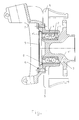
- the wheel bearing is designated 1. It is designed as an integrated unit, the roller bearing 2 and the wheel flange 3 are positively connected to one another are.
- the roller bearing 2 is pressed into the bore of the housing 4, which in this Case has two brake carrier arms 5, which are integrated in the housing 4.
- the brake disc (not shown) is also arranged.
- the housing 4 can be made of high quality Ductile iron (GGG) or steel can be manufactured and offers high strength to absorb the wheel bearing and braking forces, as well as a good bearing seat for the rolling bearing 2. Because nodular cast iron and roller bearing steel have almost the same coefficient of thermal expansion the problems mentioned at the beginning do not arise.
- GGG Ductile iron
- Screws 6 is the housing 4 with the wheel bearing unit 1 on the wheel carrier 7 made of aluminum attached, at the same time an axial bracing of the rolling bearing by the approach 8 2 takes place so that crackling noises are avoided.
- a sheet metal lid 9 which is also made of aluminum, protects the roller bearing 2 from dirt.
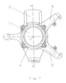
- FIG. 2 only the bearing unit 1, the housing 4 with the brake carrier arms are shown for simplification 5 and the wheel carrier 7 designated.
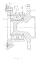
- FIGS. 4 and 5 show an embodiment very similar to that of FIGS. 1 and 3.
- a plastically deformable extension 8 ' is attached to the wheel carrier 7. This only presses with a certain force on the outer ring end of the bearing unit 1.
Landscapes
- Engineering & Computer Science (AREA)
- Mechanical Engineering (AREA)
- General Engineering & Computer Science (AREA)
- Rolling Contact Bearings (AREA)
- Arrangement Or Mounting Of Propulsion Units For Vehicles (AREA)
- Braking Arrangements (AREA)
- Vehicle Body Suspensions (AREA)
- Motor Power Transmission Devices (AREA)
Abstract
Description
- Figur 1
- eine erfindungsgemäße Baueinheit im Schnitt.
- Figur 2
- eine erfindungsgemäße Baueinheit in der Seitenansicht.
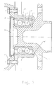
- Figur 3
- eine erfindungsgemäße Baueinheit im Schnitt mit einem umlaufenden elastischen Ansatz.
- Figur 4
- eine erfindungsgemäße Baueinheit im Schnitt mit einem plastisch verformbaren Ansatz in nicht eingebautem Zustand.
- Figur 5
- eine erfindungsgemäße Baueinheit im Schnitt mit einem plastisch verformbaren Ansatz in eingebautem Zustand.
Claims (2)
- Baueinheit für Kraftfahrzeugräder, bestehend aus einem Leichtbauradträger oder Schwenklager (3) einer Radlagerung (1), die mit zylindrischem Außendurchmesser in ein Gehäuse (4) eingepreßt ist, welches mit integrierten Bremsbefestigungsmitteln (5) versehen ist und mit einem Radträger (7) aus Aluminium oder Eisenguß/Stahl derart axial verschraubt ist, daß dabei gleichzeitig die Radlagereinheit verspannt und befestigt ist, dadurch gekennzeichnet, daß der Radträger (7) oder das Gehäuse (4) im Bereich der Stirnseite des Außenrings des Wälzlagers (2) mit elastisch oder plastisch verformbaren Ansätzen (8, 8') versehen ist.
- Baueinheit nach Anspruch 1, dadurch gekennzeichnet, daß die verformbaren Ansätze (8, 8') als eine umlaufende Schulter ausgebildet sind.
Applications Claiming Priority (2)
| Application Number | Priority Date | Filing Date | Title |
|---|---|---|---|
| DE19742027A DE19742027C2 (de) | 1997-09-24 | 1997-09-24 | Radlagerung für Kraftfahrzeugräder |
| DE19742027 | 1997-09-24 |
Publications (3)
| Publication Number | Publication Date |
|---|---|
| EP0904956A2 true EP0904956A2 (de) | 1999-03-31 |
| EP0904956A3 EP0904956A3 (de) | 2001-08-16 |
| EP0904956B1 EP0904956B1 (de) | 2004-07-28 |
Family
ID=7843396
Family Applications (1)
| Application Number | Title | Priority Date | Filing Date |
|---|---|---|---|
| EP98810927A Expired - Lifetime EP0904956B1 (de) | 1997-09-24 | 1998-09-17 | Baueinheit für Kraftfahrzeugräder |
Country Status (5)
| Country | Link |
|---|---|
| US (1) | US6170919B1 (de) |
| EP (1) | EP0904956B1 (de) |
| AT (1) | ATE271976T1 (de) |
| BR (1) | BR9803594A (de) |
| DE (2) | DE19742027C2 (de) |
Cited By (4)
| Publication number | Priority date | Publication date | Assignee | Title |
|---|---|---|---|---|
| FR2800324A1 (fr) * | 1999-10-29 | 2001-05-04 | Peugeot Citroen Automobiles Sa | Train roulant a palier serti |
| EP2037134A1 (de) * | 2007-09-11 | 2009-03-18 | Georg Fischer GmbH & Co. KG | Lageranordnung für Kraftfahrzeuge |
| DE10138412B4 (de) * | 2001-08-04 | 2010-08-05 | Dr. Ing. H.C. F. Porsche Aktiengesellschaft | Radträger für eine Lagervorrichtung eines Rades |
| US11279172B2 (en) | 2017-09-05 | 2022-03-22 | Aktiebolaget Skf | Modular wheel-hub bearing unit |
Families Citing this family (23)
| Publication number | Priority date | Publication date | Assignee | Title |
|---|---|---|---|---|
| DE19937336A1 (de) | 1999-08-11 | 2001-02-15 | Fischer Georg Fahrzeugtech | Trägeranordnung für Kraftfahrzeuge |
| US6485188B1 (en) * | 2000-04-21 | 2002-11-26 | The Timken Company | Wheel mounting with a bearing race embedded in a cast component |
| JP4911333B2 (ja) * | 2001-07-18 | 2012-04-04 | 株式会社ジェイテクト | 車輪用軸受装置における車輪取付け構造 |
| ITTO20010188U1 (it) * | 2001-10-10 | 2003-04-10 | Skf Ind Spa | Gruppo mozzo e rotore di frenatura per una ruota di un veicolo. |
| ITTO20010229U1 (it) * | 2001-12-10 | 2003-06-10 | Skf Ind Spa | Gruppo integrato per il collegamento di un mozzo e di altri organi alla sospensione della ruota di un autoveicolo. |
| JP4177057B2 (ja) * | 2002-09-11 | 2008-11-05 | Ntn株式会社 | 車輪用軸受装置 |
| US6883816B2 (en) * | 2002-11-26 | 2005-04-26 | Delphi Technologies, Inc. | Automotive brake corner module |
| JP2004322834A (ja) * | 2003-04-24 | 2004-11-18 | Nsk Ltd | 車輪用回転支持装置 |
| DE10359646A1 (de) * | 2003-12-18 | 2005-07-28 | Fag Kugelfischer Ag | Radlager in einem Radträger |
| JP2005324714A (ja) * | 2004-05-17 | 2005-11-24 | Ntn Corp | 車輪用軸受装置 |
| DE102004034565A1 (de) * | 2004-07-17 | 2006-02-16 | Daimlerchrysler Ag | Achsschenkel oder Radträger mit integriertem Bremsträger |
| DE102004055205A1 (de) * | 2004-11-16 | 2006-05-18 | Fag Kugelfischer Ag & Co. Ohg | Einheit aus wenigstens einem Träger und aus einem Radlager |
| JP4706242B2 (ja) * | 2004-11-30 | 2011-06-22 | 株式会社ジェイテクト | 転がり軸受装置の製造方法および転がり軸受装置 |
| EP1722115B1 (de) * | 2005-05-12 | 2015-10-07 | NTN Corporation | Radlagereinheit |
| JP4345988B2 (ja) * | 2007-04-16 | 2009-10-14 | Ntn株式会社 | 車輪用軸受装置 |
| JP2011149529A (ja) * | 2010-01-25 | 2011-08-04 | Uchiyama Manufacturing Corp | 封止キャップ |
| IT1399562B1 (it) * | 2010-04-15 | 2013-04-19 | Skf Ab | Anello flangiato di cuscinetto per un'unita' cuscinetto della ruota di un veicolo a motore |
| ITTO20130023A1 (it) * | 2013-01-11 | 2014-07-12 | Skf Ab | Unità mozzo di peso leggero con anelli di cuscinetto integrati, e procedimento per la sua fabbricazione |
| ITTO20130027A1 (it) * | 2013-01-11 | 2014-07-12 | Skf Ab | Unità mozzo di peso leggero con anelli di cuscinetto integrati, e procedimenti per la sua fabbricazione |
| US9694627B2 (en) * | 2015-06-29 | 2017-07-04 | Aktiebolaget Skf | Hub-bearing having a light alloy rotor-hub |
| IT201700058071A1 (it) * | 2017-05-29 | 2018-11-29 | Skf Ab | Gruppo cuscinetto mozzo-ruota |
| IT201700099283A1 (it) * | 2017-09-05 | 2019-03-05 | Skf Ab | Dispositivo di tenuta per gruppo mozzo-ruota e gruppo mozzo-ruota equipaggiato con tale dispositivo di tenuta |
| CN114261245A (zh) * | 2020-09-16 | 2022-04-01 | 舍弗勒技术股份两合公司 | 悬架组件和悬架系统 |
Citations (2)
| Publication number | Priority date | Publication date | Assignee | Title |
|---|---|---|---|---|
| DE3340442A1 (de) | 1982-12-13 | 1984-06-14 | Alfred Teves Gmbh, 6000 Frankfurt | Baugruppe fuer die anbringung von radachsen und bremsen bei kraftfahrzeugen |
| DE19538212A1 (de) | 1995-10-13 | 1997-04-17 | Lucas Ind Plc | Achsbaugruppe |
Family Cites Families (6)
| Publication number | Priority date | Publication date | Assignee | Title |
|---|---|---|---|---|
| JPS5338847A (en) * | 1976-09-21 | 1978-04-10 | Ntn Toyo Bearing Co Ltd | Bearing pre-pressure regulating method |
| DE2903229C2 (de) * | 1979-01-29 | 1981-04-02 | Uni-Cardan Ag, 5200 Siegburg | Einrichtung zur Befestigung eines Fahrzeugrades an einer über ein Gleichlaufdrehgelenk antreibbaren, an einem Radträger gelagerten Radnabe |
| DE3042449A1 (de) * | 1980-11-11 | 1982-05-27 | Löhr & Bromkamp GmbH, 6050 Offenbach | Lagerungsanordnung |
| US4798560A (en) * | 1985-02-19 | 1989-01-17 | General Motors Corporation | Unitized wheel bearing assembly |
| US5386630A (en) * | 1993-09-27 | 1995-02-07 | The Timken Company | Process and tool for adjusting bearings |
| JP3634897B2 (ja) * | 1995-07-19 | 2005-03-30 | トヨタ自動車株式会社 | ボルトの嵌合部構造 |
-
1997
- 1997-09-24 DE DE19742027A patent/DE19742027C2/de not_active Expired - Fee Related
-
1998
- 1998-08-23 BR BR9803594-0A patent/BR9803594A/pt not_active Application Discontinuation
- 1998-09-17 EP EP98810927A patent/EP0904956B1/de not_active Expired - Lifetime
- 1998-09-17 AT AT98810927T patent/ATE271976T1/de not_active IP Right Cessation
- 1998-09-17 DE DE59811707T patent/DE59811707D1/de not_active Expired - Lifetime
- 1998-09-24 US US09/160,132 patent/US6170919B1/en not_active Expired - Fee Related
Patent Citations (2)
| Publication number | Priority date | Publication date | Assignee | Title |
|---|---|---|---|---|
| DE3340442A1 (de) | 1982-12-13 | 1984-06-14 | Alfred Teves Gmbh, 6000 Frankfurt | Baugruppe fuer die anbringung von radachsen und bremsen bei kraftfahrzeugen |
| DE19538212A1 (de) | 1995-10-13 | 1997-04-17 | Lucas Ind Plc | Achsbaugruppe |
Cited By (5)
| Publication number | Priority date | Publication date | Assignee | Title |
|---|---|---|---|---|
| FR2800324A1 (fr) * | 1999-10-29 | 2001-05-04 | Peugeot Citroen Automobiles Sa | Train roulant a palier serti |
| DE10138412B4 (de) * | 2001-08-04 | 2010-08-05 | Dr. Ing. H.C. F. Porsche Aktiengesellschaft | Radträger für eine Lagervorrichtung eines Rades |
| EP2037134A1 (de) * | 2007-09-11 | 2009-03-18 | Georg Fischer GmbH & Co. KG | Lageranordnung für Kraftfahrzeuge |
| US11279172B2 (en) | 2017-09-05 | 2022-03-22 | Aktiebolaget Skf | Modular wheel-hub bearing unit |
| US11807037B2 (en) | 2017-09-05 | 2023-11-07 | Aktiebolaget Skf | Modular wheel-hub bearing unit |
Also Published As
| Publication number | Publication date |
|---|---|
| DE19742027C2 (de) | 2001-08-30 |
| DE59811707D1 (de) | 2004-09-02 |
| US6170919B1 (en) | 2001-01-09 |
| EP0904956B1 (de) | 2004-07-28 |
| ATE271976T1 (de) | 2004-08-15 |
| DE19742027A1 (de) | 1999-04-01 |
| BR9803594A (pt) | 1999-09-28 |
| EP0904956A3 (de) | 2001-08-16 |
Similar Documents
| Publication | Publication Date | Title |
|---|---|---|
| EP0904956B1 (de) | Baueinheit für Kraftfahrzeugräder | |
| DE60106767T2 (de) | Elastisches gelenk mit veränderlicher, radialer steifigkeit | |
| EP1065403A1 (de) | Bremsscheibe | |
| DE29614320U1 (de) | Radschraube | |
| DE19913024A1 (de) | Radlagerung für Fahrzeugachsen | |
| DE3508039C2 (de) | Innen umgriffene Scheibenbremse, insbesondere für Kraftfahrzeuge | |
| DE19723578C2 (de) | Radlagerung | |
| DE60201602T2 (de) | Lenkbare radaufhängung mit geteiltem achsschenkelbolzenträger | |
| DE19638842C2 (de) | Baueinheit für Kraftfahrzeugräder | |
| DE60315978T2 (de) | Vorrichtung für eine lenkbare aufhängung eines fahrzeugrads | |
| EP1789695A1 (de) | Scheibenbremse für ein fahrzeug, insbesondere ein nutzfahrzeug | |
| DE69129597T2 (de) | Radachse | |
| EP0121601B1 (de) | Bremszange für eine Scheibenbremse | |
| DE10241157A1 (de) | Scheibenbremse | |
| DE19858243B4 (de) | Bremsscheibe für Scheibenbremsen | |
| WO2017080794A1 (de) | Radlagervorrichtung, sowie verfahren zur montage einer radlagervorrichtung | |
| EP2507530A1 (de) | Radbaugruppe | |
| WO2025003176A1 (de) | Radaufhängung für einen kraftwagen | |
| WO2001036252A1 (de) | Achsschenkel mit minimaler wandstärkendifferenz | |
| DE20119640U1 (de) | Radlagerung an einem Achskörper für Fahrzeuge | |
| EP1081019B1 (de) | Achsbaugruppe insbesondere für eine lenkbare Achse eines Kraftfahrzeuges | |
| DE60213220T3 (de) | Scheibenbremse | |
| DE19946891A1 (de) | Achsbaugruppe insbesondere für eine lenkbare Achse eines Kraftfahrzeuges | |
| DE69808236T2 (de) | Schraube zur Befestigung eines Fahrzeugrades aus Leichtmetall oder Blech | |
| DE102019113939A1 (de) | Achsschenkel eines Nutzfahrzeuges |
Legal Events
| Date | Code | Title | Description |
|---|---|---|---|
| PUAI | Public reference made under article 153(3) epc to a published international application that has entered the european phase |
Free format text: ORIGINAL CODE: 0009012 |
|
| AK | Designated contracting states |
Kind code of ref document: A2 Designated state(s): AT BE CH DE FR GB LI |
|
| AX | Request for extension of the european patent |
Free format text: AL;LT;LV;MK;RO;SI |
|
| PUAL | Search report despatched |
Free format text: ORIGINAL CODE: 0009013 |
|
| AK | Designated contracting states |
Kind code of ref document: A3 Designated state(s): AT BE CH CY DE DK ES FI FR GB GR IE IT LI LU MC NL PT SE |
|
| AX | Request for extension of the european patent |
Free format text: AL;LT;LV;MK;RO;SI |
|
| 17P | Request for examination filed |
Effective date: 20011224 |
|
| AKX | Designation fees paid |
Free format text: AT BE CH DE FR GB LI |
|
| 17Q | First examination report despatched |
Effective date: 20021204 |
|
| GRAP | Despatch of communication of intention to grant a patent |
Free format text: ORIGINAL CODE: EPIDOSNIGR1 |
|
| GRAS | Grant fee paid |
Free format text: ORIGINAL CODE: EPIDOSNIGR3 |
|
| GRAA | (expected) grant |
Free format text: ORIGINAL CODE: 0009210 |
|
| AK | Designated contracting states |
Kind code of ref document: B1 Designated state(s): AT BE CH DE FR GB LI |
|
| REG | Reference to a national code |
Ref country code: GB Ref legal event code: FG4D Free format text: NOT ENGLISH |
|
| REG | Reference to a national code |
Ref country code: CH Ref legal event code: EP |
|
| REF | Corresponds to: |
Ref document number: 59811707 Country of ref document: DE Date of ref document: 20040902 Kind code of ref document: P |
|
| PG25 | Lapsed in a contracting state [announced via postgrant information from national office to epo] |
Ref country code: AT Free format text: LAPSE BECAUSE OF NON-PAYMENT OF DUE FEES Effective date: 20040917 |
|
| PG25 | Lapsed in a contracting state [announced via postgrant information from national office to epo] |
Ref country code: LI Free format text: LAPSE BECAUSE OF NON-PAYMENT OF DUE FEES Effective date: 20040930 Ref country code: CH Free format text: LAPSE BECAUSE OF NON-PAYMENT OF DUE FEES Effective date: 20040930 Ref country code: BE Free format text: LAPSE BECAUSE OF NON-PAYMENT OF DUE FEES Effective date: 20040930 |
|
| GBT | Gb: translation of ep patent filed (gb section 77(6)(a)/1977) |
Effective date: 20041019 |
|
| BERE | Be: lapsed |
Owner name: GEORG FISCHER FAHRZEUGTECHNIK A.G. Effective date: 20040930 |
|
| ET | Fr: translation filed | ||
| REG | Reference to a national code |
Ref country code: CH Ref legal event code: PL |
|
| PLBE | No opposition filed within time limit |
Free format text: ORIGINAL CODE: 0009261 |
|
| STAA | Information on the status of an ep patent application or granted ep patent |
Free format text: STATUS: NO OPPOSITION FILED WITHIN TIME LIMIT |
|
| 26N | No opposition filed |
Effective date: 20050429 |
|
| BERE | Be: lapsed |
Owner name: GEORG *FISCHER FAHRZEUGTECHNIK A.G. Effective date: 20040930 |
|
| PGFP | Annual fee paid to national office [announced via postgrant information from national office to epo] |
Ref country code: FR Payment date: 20101005 Year of fee payment: 13 |
|
| PGFP | Annual fee paid to national office [announced via postgrant information from national office to epo] |
Ref country code: GB Payment date: 20100921 Year of fee payment: 13 |
|
| PGFP | Annual fee paid to national office [announced via postgrant information from national office to epo] |
Ref country code: DE Payment date: 20100922 Year of fee payment: 13 |
|
| GBPC | Gb: european patent ceased through non-payment of renewal fee |
Effective date: 20110917 |
|
| REG | Reference to a national code |
Ref country code: FR Ref legal event code: ST Effective date: 20120531 |
|
| REG | Reference to a national code |
Ref country code: DE Ref legal event code: R119 Ref document number: 59811707 Country of ref document: DE Effective date: 20120403 |
|
| PG25 | Lapsed in a contracting state [announced via postgrant information from national office to epo] |
Ref country code: DE Free format text: LAPSE BECAUSE OF NON-PAYMENT OF DUE FEES Effective date: 20120403 |
|
| PG25 | Lapsed in a contracting state [announced via postgrant information from national office to epo] |
Ref country code: FR Free format text: LAPSE BECAUSE OF NON-PAYMENT OF DUE FEES Effective date: 20110930 Ref country code: GB Free format text: LAPSE BECAUSE OF NON-PAYMENT OF DUE FEES Effective date: 20110917 |