EP0904904B1 - Biegevorrichtung für Klammermaschine - Google Patents
Biegevorrichtung für Klammermaschine Download PDFInfo
- Publication number
- EP0904904B1 EP0904904B1 EP98117923A EP98117923A EP0904904B1 EP 0904904 B1 EP0904904 B1 EP 0904904B1 EP 98117923 A EP98117923 A EP 98117923A EP 98117923 A EP98117923 A EP 98117923A EP 0904904 B1 EP0904904 B1 EP 0904904B1
- Authority
- EP
- European Patent Office
- Prior art keywords
- staple
- legs
- bend
- guiding
- leg
- Prior art date
- Legal status (The legal status is an assumption and is not a legal conclusion. Google has not performed a legal analysis and makes no representation as to the accuracy of the status listed.)
- Expired - Lifetime
Links
- 238000005452 bending Methods 0.000 claims description 12
- 238000010586 diagram Methods 0.000 description 6
- 230000002452 interceptive effect Effects 0.000 description 4
- 238000010276 construction Methods 0.000 description 1
- 230000000694 effects Effects 0.000 description 1
- 238000000034 method Methods 0.000 description 1
- 230000002093 peripheral effect Effects 0.000 description 1
Images


Classifications
-
- B—PERFORMING OPERATIONS; TRANSPORTING
- B27—WORKING OR PRESERVING WOOD OR SIMILAR MATERIAL; NAILING OR STAPLING MACHINES IN GENERAL
- B27F—DOVETAILED WORK; TENONS; SLOTTING MACHINES FOR WOOD OR SIMILAR MATERIAL; NAILING OR STAPLING MACHINES
- B27F7/00—Nailing or stapling; Nailed or stapled work
- B27F7/17—Stapling machines
- B27F7/19—Stapling machines with provision for bending the ends of the staples on to the work
Definitions
- the present invention relates to a staple clinching mechanism for bending the legs of a staple driven by the driver of a stapler in a clincher portion after the legs thereof are passed through sheets of paper.
- a clinching mechanism is known for example from EP-A-0,322,906.
- Staplers are used for binding sheets of paper by bending the legs of U-shaped staples substantially to right angles after the staples are driven into and passed through the sheets of paper. Since the legs of such a staple are normally bent so that the pointed ends of the legs are directed closer to each other, the legs may collide and interfere with each other, thus resulting in bending inappropriately.
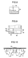
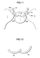
- a heretofore known method is, as shown in Fig. 11, to place the boundary 21 between bend guiding surfaces 20a, 20b on either side of a clincher portion 20 in a position deviating toward one leg-bending surface 20a.
- the legs 22 of a staple are brought into contact with the respective bend guiding surfaces 20a, 20b of the clincher portion after the legs are passed through sheets of paper and the leading ends of the legs are increasingly curled while they are being guided inward. Since the boundary of the clincher portion is deviated to one side, the deviation causes the leading end of the leg 22 on the left-hand side in Fig.
- leg 22 on the right-hand side is curled after some delay. Consequently, the leading end of the leg 22 that has been bent after some delay is so formed as to hold tightly to itself what has been bent previously, whereby the legs are prevented from interfering from each other.
- An object of the present invention intended to solve the foregoing problems is to provide a staple clinching mechanism to a stapler so that both legs of a staple are prevented from interfering with each other when the legs thereof are bent.
- a staple clinching mechanism in a stapler wherein both legs of a staple driven in by a driving mechanism are bent in a first direction after the legs of the staple are passed through stacked work sheets, comprising: a pair of movable clinchers; characterised by a guiding piece including a pair of curved bend guiding surfaces, for guiding bending the legs of the staple, wherein one of the bend guiding surfaces is inclined in a second direction which is perpendicular to the first direction.
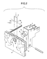
- Fig. 1 shows an electric stapler according to an embodiment of the present invention.
- the electric stapler has a base a and a magazine b mounted thereon.
- This electric stapler is used for driving a driver 1 by means of an electric motor and a driving mechanism (which are not shown) in order to pass a staple 2 through a material P (stacked work sheets, for instance, papers) to be bound on a binding stand 3 and when the legs 2a of the staple 2 are driven in until the tips of the legs passes through the material P on the binding stand 3 and projects downward from the underside of the material, each of the tips thereof is arranged so that it is inserted in between two sheets of longitudinal clincher guides 4 disposed in parallel to each other with a predetermined gap therebetween.
- a driver 1 by means of an electric motor and a driving mechanism (which are not shown) in order to pass a staple 2 through a material P (stacked work sheets, for instance, papers) to be bound on a binding stand 3 and when the legs 2a of the staple 2 are driven in until the tips of the legs passes through the material P on the binding stand 3 and projects downward from the under
- a columnar force-cutting cutter 5 for cutting off the excess part of each leg 2a of the staple 2 and a moving clincher 6 (see Fig. 2) installed on both sides of the cutter 5 are disposed inside the gap between the clincher guides 4.
- the cutter 5 also serves as a guiding piece for guiding legs, as described later. Part of each leg 2a of the staple 2 driven in by the driver 1 is cut off by the force-cutting cutter 5 after the legs are passed through the material to be bound and bent by the moving clincher 6.
- the force-cutting cutter 5 is formed at the front end of a driving link 7 in such a way as to move in and out of cutting holes 8 formed in the respective clincher guides 4.
- the force-cutting cutter 5 is moved forward and by passing the force-cutting cutter 5 through the cutting holes 8 of the respective clincher guides 4, the projecting leading ends of the legs 2a of the staple 2 in the cutting holes 8 are cut off by force-cutting with the upper peripheral edge of the force-cutting cutter 5.
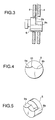
- a clincher portion 9 is formed in the lower portion of the edge face 5a of the cutter 5. Furthermore, the clincher portion 9 is, as shown in Figs. 3 to 5, formed with a pair of laterally-disposed bend guiding surfaces 9a, 9b for receiving the respective legs 2a of the staple 2 in order to guide their bends.
- the bend guiding surfaces 9a, 9b are curved and the curving degrees of the bend guiding surfaces 9a, 9b on either side are set different from each other.
- the boundary 10 between the bend guiding surfaces 9a, 9b on either side is arranged in a way deviating from the center of the force-cutting cutter 5 toward one bend-guiding surface 9a.
- the bend guiding surface 9a on the left-hand side of Fig. 3 is inclined in a direction perpendicular to the leg guiding direction; more specifically, the surface gradually becomes lower as the distance from the edge face 5a of the cutter 5 increases.
- the moving clinchers 6 are mounted pivotally on support shafts 11 provided to the respective clincher guides 4 and used for receiving the legs 2a of the staple 2 passed through the material P first and subjecting the staple 2 to preliminary bending and then pivoted between a first position (the position shown in Fig. 7(a)) where the legs 2a of the staple 2 are introduced to the clincher portion 9 and a second position (what is shown in Fig. 7(b)) where the legs 2a of the staple 2 bent in the clincher portion 9 are forced to bend toward the material P and pressed against the underside of the material P.
- the clincher portion 9 is formed so that it stays in between the two sheets of clincher guides 4 when the force-cutting cutter 5 is moved back after it has cut off part of each leg of the staple 2.
- operating timing is so controlled as to make the moving clinchers 6 operate when the force-cutting cutter 5 operates to cut off part of each leg 2a of the staple 2 after the driver 1 reaches to the lowest point.
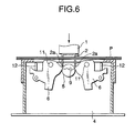
- the legs 2a of the staple 2 passed through the material P are inserted in between the clincher guides 4 by the driver 1 as shown in Fig. 6 and the tips of the legs are brought into contact with the inclined surfaces of the respective moving clinchers 6 placed in the first position, guided and curved inward along the respective surfaces and subjected to the preliminary bending.
- the force-cutting cutter 5 is subsequently operated then, any part of each leg 2a is not cut off if the length of the excessive part thereof passed through the material P is short.
- the clinch mechanism operates to force driving levers 12, which are forced up as shown in Fig. 7(a).
- the leading ends of the rear ends of the moving clinchers 6 are pivoted upward around the respective support shafts 11, so that the legs 2a of the staple 2 are increasingly forced to bend.
- the leading ends of the legs 2a of the staple 2 are each guided slidably along the bend guiding surfaces 9a, 9b formed in the clincher portion 9 in the lower portion of the edge face 5a of the cutter 5 while the moving clinchers 6 are moving to the second position and part of each leg 2a passed through the material P is totally curled before being bent finally as shown in Fig. 7(b).
- the boundary 10 between both the aforesaid bend guiding surfaces in a position deviating toward the one bend guiding surface has the effect of making both legs 2a hardly interfere with each other because of the aforesaid time difference in bending both legs 2a.
- the boundary 10 may be formed at the center of the force-cutting cutter 5 as the one leg 2a is bent in a direction perpendicular to the leg guiding direction along the bend guiding surface 9a.
Landscapes
- Engineering & Computer Science (AREA)
- Mechanical Engineering (AREA)
- Life Sciences & Earth Sciences (AREA)
- Forests & Forestry (AREA)
- Portable Nailing Machines And Staplers (AREA)
Claims (4)
- Eine Klammerbiegevorrichtung für eine Klammermaschine, bei der beide Schenkel (2a, 2a) einer durch einen Eintreibmechanismus (1) eingetriebenen Klammer (2) in eine erste Richtung gebogen werden, nachdem die Schenkel der Klammer durch gestapelte Arbeitsbögen geführt sind, umfassend:ein Paar schwenkbarer Biegevorrichtungen (6, 6); gekennzeichnet durchein Führungsteil (9) mit einem Paar gekrümmter Biegeführungsflächen (9a, 9b) zum geführten Biegen der Schenkel der Klammer, wobei eine der Biegeführungsflächen (9a) in eine zweite Richtung geneigt ist, die senkrecht zu der ersten Richtung ist.
- Klammerbiegevorrichtung nach Anspruch 1, bei welcher eine Grenze zwischen den beiden Biegeführungsflächen derart vorgesehen ist, daß sie in Richtung einer der Biegeführungsflächen versetzt ist.
- Klammerbiegevorrichtung nach Anspruch 1, bei welcher das Führungsteil Säulenform hat, mit Ausnahme der Biegeführungsflächen.
- Klammerbiegevorrichtung nach Anspruch 1, bei welcher die Biegeführungsflächen derart gekrümmt sind, daß jede der Biegeführungsflächen glatt von einer jeweiligen der Biegevorrichtungen fortgesetzt wird, wenn die Biegevorrichtungen in ihren anfänglichen Stellungen sind.
Applications Claiming Priority (3)
| Application Number | Priority Date | Filing Date | Title |
|---|---|---|---|
| JP27641597A JP3598765B2 (ja) | 1997-09-24 | 1997-09-24 | ホッチキスにおけるステープルのクリンチ機構 |
| JP276415/97 | 1997-09-24 | ||
| JP27641597 | 1997-09-24 |
Publications (3)
| Publication Number | Publication Date |
|---|---|
| EP0904904A2 EP0904904A2 (de) | 1999-03-31 |
| EP0904904A3 EP0904904A3 (de) | 1999-11-17 |
| EP0904904B1 true EP0904904B1 (de) | 2003-06-25 |
Family
ID=17569098
Family Applications (1)
| Application Number | Title | Priority Date | Filing Date |
|---|---|---|---|
| EP98117923A Expired - Lifetime EP0904904B1 (de) | 1997-09-24 | 1998-09-22 | Biegevorrichtung für Klammermaschine |
Country Status (4)
| Country | Link |
|---|---|
| US (1) | US6036074A (de) |
| EP (1) | EP0904904B1 (de) |
| JP (1) | JP3598765B2 (de) |
| DE (1) | DE69815774T2 (de) |
Families Citing this family (33)
| Publication number | Priority date | Publication date | Assignee | Title |
|---|---|---|---|---|
| JP3539232B2 (ja) * | 1998-10-19 | 2004-07-07 | マックス株式会社 | 電動ホッチキスにおけるステープル脚部の切断機構 |
| JP2002355803A (ja) * | 2001-05-31 | 2002-12-10 | Nisca Corp | ステープル装置 |
| JP2002355772A (ja) * | 2001-05-31 | 2002-12-10 | Nisca Corp | ステープル装置 |
| GB2376912B (en) * | 2001-06-27 | 2003-04-09 | Isaberg Rapid Ab | Clinching mechanism for staplers |
| SE524128C2 (sv) * | 2002-01-11 | 2004-06-29 | Isaberg Rapid Ab | Handdriven häftapparat med vikare samverkande med klippdyna för klammer |
| JP4232371B2 (ja) * | 2002-01-11 | 2009-03-04 | マックス株式会社 | ステープラー |
| JP4103724B2 (ja) * | 2003-08-11 | 2008-06-18 | マックス株式会社 | ステープラにおける紙押えテーブルのロック機構 |
| US7093339B2 (en) | 2003-08-20 | 2006-08-22 | Hewlett-Packard Development Company, L.P. | Media fastening |
| US7111378B2 (en) * | 2003-08-20 | 2006-09-26 | Hewlett-Packard Development Company, L.P. | Fastener closing |
| US6942136B2 (en) * | 2003-10-21 | 2005-09-13 | Apex Mfg. Co., Ltd. | Stapler apparatus to staple stacks of paper with different thicknesses |
| DE602005019972D1 (de) * | 2004-01-13 | 2010-04-29 | Max Co Ltd | Klammermaschine |
| SE525408C2 (sv) * | 2004-02-05 | 2005-02-15 | Isaberg Rapid Ab | Häftapparat med spärrarrangemang |
| JP4407359B2 (ja) * | 2004-04-14 | 2010-02-03 | マックス株式会社 | ステープラ |
| US6981627B2 (en) * | 2004-04-21 | 2006-01-03 | Apex Mfg. Co., Ltd. | Electric stapler having an apparatus to bend staple legs and the apparatus |
| JP4420208B2 (ja) * | 2004-05-27 | 2010-02-24 | マックス株式会社 | ステープラーのクリンチャ装置 |
| US6981626B1 (en) * | 2004-12-08 | 2006-01-03 | Apex Mfg. Co., Ltd. | Stapler with a leg-cutting device |
| US7108165B2 (en) * | 2004-12-08 | 2006-09-19 | Apex Mfg. Co., Ltd. | Stapler capable of cutting staple legs one after another |
| JP4613602B2 (ja) * | 2004-12-15 | 2011-01-19 | マックス株式会社 | ステープラーにおけるステープルカートリッジ及びステープル脚切断屑処理装置 |
| US7334716B2 (en) * | 2005-01-26 | 2008-02-26 | Apex Mfg. Co., Ltd. | Stapler capable of cutting staple legs one after another |
| US7311236B2 (en) * | 2005-04-25 | 2007-12-25 | Tsi Manufacturing Llc | Electric stapler having two anvil plates and workpiece sensing controller |
| US7159749B2 (en) * | 2005-05-31 | 2007-01-09 | Apex Mfg. Co., Ltd. | Stapler capable of cutting staple legs |
| US7124926B1 (en) | 2005-06-09 | 2006-10-24 | Apex Mfg. Co., Ltd. | Stapler capable of cutting staple legs |
| US20070023474A1 (en) * | 2005-07-14 | 2007-02-01 | Smith Robert S | Clincher for a heavy duty stapler |
| JP5359694B2 (ja) * | 2008-10-17 | 2013-12-04 | マックス株式会社 | ステープラのクリンチャ機構 |
| JP5919616B2 (ja) * | 2010-03-16 | 2016-05-18 | 株式会社川崎エンジニアリング | 軟質材から成る針の針群内装保持ケース具及びそれらを備えたステープラ器具 |
| JP5716578B2 (ja) * | 2011-07-01 | 2015-05-13 | マックス株式会社 | ステープラ |
| US20130240594A1 (en) * | 2012-03-19 | 2013-09-19 | Stanley Fastening Systems, L.P. | Cordless carton closer |
| JP6040746B2 (ja) * | 2012-12-12 | 2016-12-07 | マックス株式会社 | ステープラ |
| US9592597B2 (en) | 2013-01-23 | 2017-03-14 | Worktools, Inc. | Flat clinch stapler anvil assembly |
| US9987734B2 (en) | 2013-01-23 | 2018-06-05 | Worktools, Inc. | Flat clinch anvil assembly |
| JP6645339B2 (ja) * | 2016-04-22 | 2020-02-14 | マックス株式会社 | ステープラ |
| JP7251105B2 (ja) * | 2018-11-02 | 2023-04-04 | マックス株式会社 | ステープラ |
| US11148270B2 (en) * | 2019-12-17 | 2021-10-19 | Apex Mfg. Co., Ltd. | Stapler |
Family Cites Families (12)
| Publication number | Priority date | Publication date | Assignee | Title |
|---|---|---|---|---|
| US4378085A (en) * | 1980-11-03 | 1983-03-29 | Xerox Corporation | Stapler apparatus having a mechanism for bending and cutting staple legs in accordance with the thickness of the work piece |
| US4593947A (en) * | 1984-08-30 | 1986-06-10 | Yocum Roderick E | Vacuum lifting device |
| JPH0354858Y2 (de) * | 1986-07-03 | 1991-12-04 | ||
| JPS6399904A (ja) * | 1986-10-16 | 1988-05-02 | マックス株式会社 | ホツチキスのステ−プル脚切断駆動装置 |
| JPH0325931Y2 (de) * | 1986-10-31 | 1991-06-05 | ||
| EP0322906B1 (de) * | 1987-12-28 | 1994-08-17 | Max Co., Ltd. | Elektrischer Heftapparat |
| JPH067893Y2 (ja) * | 1987-12-28 | 1994-03-02 | マックス株式会社 | ステープルクリンチャ |
| US5413266A (en) * | 1991-09-17 | 1995-05-09 | Acco Usa, Inc. | Compact gear arm powered stapler with movable anvil |
| US5791543A (en) * | 1995-12-11 | 1998-08-11 | Max Co., Ltd. | Electric stapler |
| SE504311C2 (sv) * | 1996-02-27 | 1997-01-13 | Isaberg Ab | Häftapparat med flatläggningsmekanism |
| JP3344455B2 (ja) * | 1996-10-25 | 2002-11-11 | マックス株式会社 | ホッチキスにおけるクリンチ機構 |
| JP3503368B2 (ja) * | 1996-10-29 | 2004-03-02 | マックス株式会社 | 電動ホッチキスのステープルの脚部切断機構 |
-
1997
- 1997-09-24 JP JP27641597A patent/JP3598765B2/ja not_active Expired - Fee Related
-
1998
- 1998-09-22 EP EP98117923A patent/EP0904904B1/de not_active Expired - Lifetime
- 1998-09-22 DE DE69815774T patent/DE69815774T2/de not_active Expired - Lifetime
- 1998-09-24 US US09/159,764 patent/US6036074A/en not_active Expired - Lifetime
Also Published As
| Publication number | Publication date |
|---|---|
| JPH1190856A (ja) | 1999-04-06 |
| DE69815774D1 (de) | 2003-07-31 |
| EP0904904A3 (de) | 1999-11-17 |
| JP3598765B2 (ja) | 2004-12-08 |
| EP0904904A2 (de) | 1999-03-31 |
| DE69815774T2 (de) | 2004-02-05 |
| US6036074A (en) | 2000-03-14 |
Similar Documents
| Publication | Publication Date | Title |
|---|---|---|
| EP0904904B1 (de) | Biegevorrichtung für Klammermaschine | |
| EP0412143B1 (de) | Führungsamboss mit bewegbaren vernietungsflügeln für heftmaschinen | |
| EP0995561B1 (de) | Schneideinrichtung der Klammerschenkel für einen elektrischen Heftapparat | |
| EP0838310A2 (de) | Biegevorrichtung in einem Heftapparat | |
| EP1604784B1 (de) | Ambossplatte für heftvorrichtung | |
| EP2236257B1 (de) | Vorrichtung zur Blattverarbeitung | |
| US6942136B2 (en) | Stapler apparatus to staple stacks of paper with different thicknesses | |
| EP0027336B1 (de) | Ambossplatte und damit ausgerüsteter Hefter | |
| EP1541289B1 (de) | Treiberkonstruktion für einen stapler | |
| US6702172B1 (en) | Staple driver with convex edge and pointed protrusions at the ends | |
| US6059504A (en) | Binding device | |
| KR101036389B1 (ko) | 카트리지 | |
| EP2127834B1 (de) | Mechanismus für Positionierung einer Klammervorrichtung eines Hefters | |
| WO2003090975A1 (en) | Stapler | |
| EP0597782A1 (de) | Motorheftvorrichtung | |
| EP0051447B1 (de) | Klammerheftgerät | |
| US20060186168A1 (en) | Stapler | |
| JPS64297Y2 (de) | ||
| EP1599317B1 (de) | Lösbares klammermagazin mit einer anordnung, die eine lösbare klammer bildet | |
| JP4650611B2 (ja) | ステープラーのクリンチャ機構 | |
| EP1749619B1 (de) | Klammervorrichtung für hefter | |
| JP3536654B2 (ja) | 電動ホッチキスのステープル成形機構 |
Legal Events
| Date | Code | Title | Description |
|---|---|---|---|
| PUAI | Public reference made under article 153(3) epc to a published international application that has entered the european phase |
Free format text: ORIGINAL CODE: 0009012 |
|
| AK | Designated contracting states |
Kind code of ref document: A2 Designated state(s): DE FR GB NL SE |
|
| AX | Request for extension of the european patent |
Free format text: AL;LT;LV;MK;RO;SI |
|
| PUAL | Search report despatched |
Free format text: ORIGINAL CODE: 0009013 |
|
| AK | Designated contracting states |
Kind code of ref document: A3 Designated state(s): AT BE CH CY DE DK ES FI FR GB GR IE IT LI LU MC NL PT SE |
|
| AX | Request for extension of the european patent |
Free format text: AL;LT;LV;MK;RO;SI |
|
| 17P | Request for examination filed |
Effective date: 20000208 |
|
| AKX | Designation fees paid |
Free format text: DE FR GB NL SE |
|
| GRAH | Despatch of communication of intention to grant a patent |
Free format text: ORIGINAL CODE: EPIDOS IGRA |
|
| GRAH | Despatch of communication of intention to grant a patent |
Free format text: ORIGINAL CODE: EPIDOS IGRA |
|
| GRAA | (expected) grant |
Free format text: ORIGINAL CODE: 0009210 |
|
| AK | Designated contracting states |
Designated state(s): DE FR GB NL SE |
|
| REG | Reference to a national code |
Ref country code: GB Ref legal event code: FG4D |
|
| REF | Corresponds to: |
Ref document number: 69815774 Country of ref document: DE Date of ref document: 20030731 Kind code of ref document: P |
|
| REG | Reference to a national code |
Ref country code: SE Ref legal event code: TRGR |
|
| ET | Fr: translation filed | ||
| PLBE | No opposition filed within time limit |
Free format text: ORIGINAL CODE: 0009261 |
|
| STAA | Information on the status of an ep patent application or granted ep patent |
Free format text: STATUS: NO OPPOSITION FILED WITHIN TIME LIMIT |
|
| 26N | No opposition filed |
Effective date: 20040326 |
|
| PGFP | Annual fee paid to national office [announced via postgrant information from national office to epo] |
Ref country code: GB Payment date: 20140917 Year of fee payment: 17 |
|
| PGFP | Annual fee paid to national office [announced via postgrant information from national office to epo] |
Ref country code: FR Payment date: 20140906 Year of fee payment: 17 |
|
| GBPC | Gb: european patent ceased through non-payment of renewal fee |
Effective date: 20150922 |
|
| REG | Reference to a national code |
Ref country code: FR Ref legal event code: ST Effective date: 20160531 |
|
| PG25 | Lapsed in a contracting state [announced via postgrant information from national office to epo] |
Ref country code: GB Free format text: LAPSE BECAUSE OF NON-PAYMENT OF DUE FEES Effective date: 20150922 |
|
| PG25 | Lapsed in a contracting state [announced via postgrant information from national office to epo] |
Ref country code: FR Free format text: LAPSE BECAUSE OF NON-PAYMENT OF DUE FEES Effective date: 20150930 |
|
| PGFP | Annual fee paid to national office [announced via postgrant information from national office to epo] |
Ref country code: NL Payment date: 20170814 Year of fee payment: 20 |
|
| PGFP | Annual fee paid to national office [announced via postgrant information from national office to epo] |
Ref country code: DE Payment date: 20170920 Year of fee payment: 20 |
|
| PGFP | Annual fee paid to national office [announced via postgrant information from national office to epo] |
Ref country code: SE Payment date: 20170912 Year of fee payment: 20 |
|
| REG | Reference to a national code |
Ref country code: DE Ref legal event code: R071 Ref document number: 69815774 Country of ref document: DE |
|
| REG | Reference to a national code |
Ref country code: NL Ref legal event code: MK Effective date: 20180921 |