EP0904867B1 - Verfahren und System zur Bestimmung des Heizpunktes und Heitzlinien im Biegeprozess einer Platte - Google Patents
Verfahren und System zur Bestimmung des Heizpunktes und Heitzlinien im Biegeprozess einer Platte Download PDFInfo
- Publication number
- EP0904867B1 EP0904867B1 EP98118299A EP98118299A EP0904867B1 EP 0904867 B1 EP0904867 B1 EP 0904867B1 EP 98118299 A EP98118299 A EP 98118299A EP 98118299 A EP98118299 A EP 98118299A EP 0904867 B1 EP0904867 B1 EP 0904867B1
- Authority
- EP
- European Patent Office
- Prior art keywords
- heating
- steel plate
- line
- point
- points
- Prior art date
- Legal status (The legal status is an assumption and is not a legal conclusion. Google has not performed a legal analysis and makes no representation as to the accuracy of the status listed.)
- Expired - Lifetime
Links
- 238000010438 heat treatment Methods 0.000 title claims description 251
- 229910000831 Steel Inorganic materials 0.000 title claims description 137
- 239000010959 steel Substances 0.000 title claims description 132
- 238000000034 method Methods 0.000 title claims description 47
- 238000005452 bending Methods 0.000 title claims description 46
- 238000005259 measurement Methods 0.000 claims description 11
- 238000005096 rolling process Methods 0.000 claims description 8
- 238000012545 processing Methods 0.000 description 98
- 239000000463 material Substances 0.000 description 8
- 238000005516 engineering process Methods 0.000 description 7
- 238000013461 design Methods 0.000 description 4
- GZPBVLUEICLBOA-UHFFFAOYSA-N 4-(dimethylamino)-3,5-dimethylphenol Chemical compound CN(C)C1=C(C)C=C(O)C=C1C GZPBVLUEICLBOA-UHFFFAOYSA-N 0.000 description 3
- 238000004364 calculation method Methods 0.000 description 3
- 230000000694 effects Effects 0.000 description 3
- 230000006378 damage Effects 0.000 description 2
- 238000009826 distribution Methods 0.000 description 2
- 238000002360 preparation method Methods 0.000 description 2
- 230000032683 aging Effects 0.000 description 1
- 238000004458 analytical method Methods 0.000 description 1
- 238000013459 approach Methods 0.000 description 1
- 238000010586 diagram Methods 0.000 description 1
- 238000002474 experimental method Methods 0.000 description 1
- 238000004519 manufacturing process Methods 0.000 description 1
- 230000001404 mediated effect Effects 0.000 description 1
- 238000003672 processing method Methods 0.000 description 1
- 230000000007 visual effect Effects 0.000 description 1
- XLYOFNOQVPJJNP-UHFFFAOYSA-N water Substances O XLYOFNOQVPJJNP-UHFFFAOYSA-N 0.000 description 1
Images


Classifications
-
- B—PERFORMING OPERATIONS; TRANSPORTING
- B21—MECHANICAL METAL-WORKING WITHOUT ESSENTIALLY REMOVING MATERIAL; PUNCHING METAL
- B21D—WORKING OR PROCESSING OF SHEET METAL OR METAL TUBES, RODS OR PROFILES WITHOUT ESSENTIALLY REMOVING MATERIAL; PUNCHING METAL
- B21D11/00—Bending not restricted to forms of material mentioned in only one of groups B21D5/00, B21D7/00, B21D9/00; Bending not provided for in groups B21D5/00 - B21D9/00; Twisting
- B21D11/20—Bending sheet metal, not otherwise provided for
-
- B—PERFORMING OPERATIONS; TRANSPORTING
- B21—MECHANICAL METAL-WORKING WITHOUT ESSENTIALLY REMOVING MATERIAL; PUNCHING METAL
- B21D—WORKING OR PROCESSING OF SHEET METAL OR METAL TUBES, RODS OR PROFILES WITHOUT ESSENTIALLY REMOVING MATERIAL; PUNCHING METAL
- B21D11/00—Bending not restricted to forms of material mentioned in only one of groups B21D5/00, B21D7/00, B21D9/00; Bending not provided for in groups B21D5/00 - B21D9/00; Twisting
- B21D11/22—Auxiliary equipment, e.g. positioning devices
Definitions
- This invention relates to a method and a system for determining a heating point and a heating line in the bending of a steel plate. More specifically, the invention relates to the method and system useful for application to the bending of a steel plate having complicated curved surfaces, such as an outer panel of a ship hull.
- the outer panel of a ship hull is composed of a steel plate about 10 to 30 mm thick with a complicated undevelopable curved surface which reduces propulsion resistance for efficient navigation in the water.
- a processing method generally called line heating has been known for long. This method heats the surface of a steel plate locally by means of a gas burner or the like, to cause the extraplane angular deformation or intraplane shrinkage deformation of the steel plate due to plastic distortion, and skillfully combines these deformations to obtain the desired shape. This method is used at many shipyards.
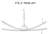
- Fig. 1 is an explanation drawing conceptually showing an earlier technology concerned with a method for bending a steel plate to serve as an outer panel of a ship hull.
- Fig. 2 is a front view showing a wooden pattern for use in the bending in a state in which it is mounted on the steel plate.
- many (10 in the drawing) wooden patterns 1 following frame lines of the outer panel of the ship hull (lines extending along frame materials for the outer panel at positions where the frame materials are attached; the same will hold in the following description) as target shapes are mounted on a steel plate 2.
- each wooden pattern 1 and the steel plate 2 by visual observation, and considers differences between their shapes, e.g., the clearance between the wooden pattern 1 and the steel plate 2. Based on this consideration, the operator studies what position to heat in order to bring the steel plate 2 close to the target shape. As a result, the operator determines each heating position (heating point) . Concretely, the wooden pattern 1 is rolled along the frame line of the steel plate 2 in a vertical plane (the same plane as in Fig. 2). The points of contact of the wooden pattern 1 with the steel plate 2 during the rolling motion are watched to determine the heating points in consideration of the clearance between the wooden pattern 1 and the steel plate 2 in each state.
- heating lines 3 that have been determined are marked on the surface of the steel plate 2 with chalk or the like, and the steel plate 2 is heated with a gas burner along the heating line 3.
- the steel plate 2 is heated with a gas burner by the operator along the heating lines 3 determined by the operator's sense based on many years of experience. As a result, a predetermined curved surface is obtained. Acquiring the ability to determine the heating lines 3 rationally is said to require more than about 5 years of experience. This has posed the problems of the aging and shortage of experienced technicians. The bending procedure also takes a large amount of time for incidental operations, such as the production, mounting and removal of the wooden pattern 1 for the steel plate 2, thus lengthening the entire operating time.
- the finite elements analysis is used, by which destruction is divided in a mesh and material features, along with a shape to be obtained, are input in the program.
- the effects of heating along specific lines are also computed in order to obtain a link between bending forces applied and localized heating.
- JP-A-07 075 835 and JP-A-07 024 534 there is disclosed the determination of heating points being a part of a calculation process taking into account geometric and physical features of the material together with forces applied and heating conditions.
- a method for determining a heating point in the bending of a steel plate which has been subjected to primary bending comprising:
- all the heating points or heating points and bending angles, on a specific line of the steel plate can be determined automatically.
- heating lines and bending angles can be determined simultaneously.
- appropriate heating lines can be prepared automatically on the basis of information on the heating points. Consequently, automatic bending of a predetermined steel plate can be carried out by controlling the position of the heating unit of the high frequency heater on the basis of data on the heating lines.
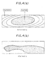
- Figs. 4(a) and 4(b) show, by contour lines, the shapes of a steel plate before and after its heating along heating lines determined by the present invention.
- Fig. 4(a) represents the contour lines before heating, indicating the difference between the shape of the steel plate and the target shape as a difference in color.
- a blue portion at the center of the steel plate has a difference of 5 mm from the target shape, while a red portion at the end of the steel plate has a difference of 50 mm.
- the deviation of the surface shape of the steel plate, the object to be processed, from the target shape is grasped as a geometrical problem mediated by the angle between the base of each isosceles triangle and the base of the adjacent isosceles triangle of the multiplicity of specific isosceles triangles.
- all the heating points on a specific line of the steel plate can be determined automatically.
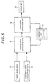
- Figs. 6(a) to 6(e) are explanation drawings for illustrating an example of processing performed by the heating point determining unit 11.
- the numeral 1' denotes a virtual wooden pattern for illustration
- the numeral 2' represents a similar virtual steel plate.
- the term "virtual” refers to the fact that the wooden pattern or steel plate at issue does not exist as a real one, but exists as electronic data or a graphic expressed in a visible form on the display unit 16.
- the processing in this example is to find the points of contact of the wooden pattern 1' with the steel plate 2' while rolling the wooden pattern 1', to determine a heating point.
- this method we call this method "a contact point finding method".
- the steel plate 2' As shown in Fig. 6(a), the steel plate 2', the object to be bent, is assumed to be one of a curved shape that has been subjected to primary bending. Such steel plate 2', when observed on a minuscule scale, is thought not to have a smoothly varying curved surface, but to be a collection of flat surfaces bent at certain linear sites. For example, as shown in Fig. 6(a), the steel plate 2' forms a flat surface in a certain range beginning on an M line, the centerline in the plate width direction, and is bent at a certain position 1 to have an angle of 10°. On the other hand, a target shape that the wooden pattern 1' has is given in Fig. 6(a).
- the wooden pattern 1' is rolled along a frame line from the initial position shown in Fig. 6(a), whereby the wooden pattern 1' is brought into contact with the steel plate 2' as shown in Fig. 6(b). At this time, contact points on the steel plate 2' are designated as A, B, while contact points on the wooden pattern 1' are designated as C, D. Then, the wooden pattern 1' is rolled in the reverse direction to return it to the initial state (the state shown in Fig. 6(a)) as shown in Fig. 6(c).
- a straight line U connecting the contact points A, B and a straight line V connecting the contact points C, D are obtained to find an intersection point P of the straight lines U, V and an angle ⁇ at which the straight lines U, V intersect.
- a heating point is determined.
- the angle ⁇ (3° in Fig. 6) is deemed as a bending angle at the heating point.
- the intersection point P is extended vertically upward in Fig. 6(d) until it reaches the steel plate 2', to determine a heating position.
- the steel plate 2' is heated at this heating position, whereby it is bent by the angle ⁇ , beginning at the heating position. This is a case shown in Fig. 6 (e).
- this heating results in the contact of the contact point B of the steel plate 2' with the contact point D of the wooden pattern 1', thus bringing the shape of the steel plate 2' close to the target shape (the shape of the wooden pattern 1").
- the intersection point P and the heating position based thereon there is a difference in the Z axis coordinate, the position in the vertical direction
- the lengths of the straight lines U, V ranging from the intersection point P to the contact points B, D are sufficiently large relative to the angle ⁇ .
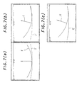
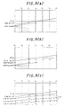
- Figs. 7(a) to 7(c) are explanation drawings conceptually illustrating display screens of the display unit 16 when the heating point is determined by the heating point determining unit 11.
- Fig. 7(a) corresponds to the initial position
- Fig. 7 (b) corresponds to a case in which the wooden pattern 1' is rolled once
- Fig. 7(c) corresponds to a case in which the wooden pattern 1' is rolled twice.
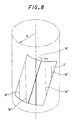
- Fig. 8 is an explanation drawing conceptually showing the blank layout of the steel plate 2, the object to be processed in the instant embodiment.
- a virtual steel plate 2' which is a part of a cylindrical surface with a radius R taken out as in the drawing is assumed in the instant embodiment.
- a roller reference line 16' is defined as indicating the direction of the central axis when the target shape is roughly deemed to be a cylindrical surface.
- Fig. 8 shows a case in which the M line, the centerline in the plate width direction, intersects the roller reference line 16'.
- the roller reference line 16' and the M line are not always in this relation. Since the steel plate 2' forms a part of the outer panel of a ship hull, for example, the roller reference line 16' and the M line may agree in a certain case.
- Figs. 9(a), (b), (c) and (d) are explanation drawings for illustrating an example of processing performed by the heating line determining unit 14. Determination of the heating line in this case is performed by connecting the heating points, which have been determined by the heating point determining unit 11, by a virtual straight line, examining the degree of parallelism between this straight line and a virtual roller line 16" drawn on a virtual steel plate 2', and grouping the heating points, whose straight lines show a predetermined degree of parallelism, into the same group. Grouping is performed while dividing the heating points into those above and those below the roller line 16".
- F 1 to F 7 represent virtual frame lines. The subscripts attached to the symbol F designate the frame line numbers. Many dots indicated narrowly at right angles to the respective frame lines F 1 to F 7 refer to the heating points.
- a starting point 1 is set first of all. From this starting point 1, virtual straight lines (indicated as dashed lines in Fig. 9) are drawn toward the heating points on the respective frame lines F 1 to F 7 . The starting point is established on the frame line of a smaller frame line No. and at a site nearer to the roller line 16".
- FIG. 9(b) shows that the heating points belonging to Group 1 based on the starting point 1 have been fixed, and the heating points based on the starting point 2 are being investigated. On this occasion, the heating points that have already been grouped are neither used as the starting points nor subjected to grouping. In this manner, the heating points lying below the roller line 16" are grouped.
- a straight line (or a curve) is obtained from the sequence of heating points in each group, as shown in Fig. 9(c), and this line is designated as a virtual heating line 3'.
- the heating line 3' is obtained by the method of least squares if it is a straight line, or by spline interpolation or the like if it is a curve.
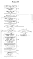
- Fig. 10 is a flow chart showing a concrete procedure (example) using the heating point determining unit 11 when obtaining the heating points by the contact point finding method.
- the heating points are obtained on the frame lines, but needless to say, the way of obtaining them is not restricted to this manner.
- the frame lines are lines corresponding to the positions at which frame materials are attached. Thus, data on their positions are stored as design data. The use of the frame lines in obtaining the heating points is advantageous in the applicability of such data. The above-mentioned procedure will be explained based on Fig. 10.
- the target shape is rolled along the steel plate, but the same effect is obtained if the steel plate is rolled along the target shape. In short, one of them may be rolled relative to the other so that the contact point of the two is obtained.
- the purpose of determining the heating points in the above manner is to obtain the heating positions and heating intensities (quantities of heat given to the steel plate) for causing the necessary change in shape. Between the heating intensity and the angle ⁇ , there is a predetermined relationship, which can be found experimentally. Thus, at a time when the angle ⁇ is found, the heating intensity can be determined (needles to say, if the angle ⁇ is recorded as data, it can be converted to the heating intensity later, where necessary) . Thus, at step S 14 , the heating intensity with respect to the angle ⁇ may be obtained along with data on the angle ⁇ , although this is not directly related to the processing for finding the heating point.
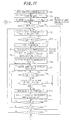
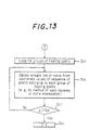
- Figs. 11 to 13 are flow charts showing a concrete procedure (example) using the heating line determining unit 14 when obtaining the heating lines on the basis of the heating points determined. This procedure will be explained based on these drawings.
- Fig. 14 shows an example in which the heating intensity (determined by the bending angle ⁇ ) at each heating point is taken into consideration during the processings illustrated in Fig. 13, and the information on the heating intensity is incorporated into the information on the heating line.
- the distribution of the heating intensity is calculated for the determined heating line by the process subsequent to step S 56 in accordance with the instant embodiment (step S 59 ).
- the heating intensity has been directly obtained separately based on the bending angle ⁇ at the heating point, or is determined on the basis of information on the bending angle ⁇ at the heating point.
- the heating points on each heating line 3 can be heated with the most appropriate quantity of heat.
- this can be easily achieved by controlling an electric current supplied to the high frequency heating coil to control the amount of heat input to the steel plate 2.
- Fig. 15 shows an example in which the heating intensity (determined by the bending angle ⁇ ) at each heating point is taken into consideration during the processings illustrated in Figs. 11 and 12, and this heating intensity is also incorporated into the conditions for grouping.
- the heating intensity is same as the heating intensity at the starting point (the heating intensity includes that within a predetermined tolerance range) (step S 60 ). If this judgment shows that the heating point in question does not have the same heating intensity, this heating point is excluded from the relevant group. In other words, the same group No. as that of the starting point is assigned to the heating point, provided that it has the same heating intensity.
- the heating points on each heating line 3 can be heated with the same quantity of heat.
- the most appropriate amount of heat input to the steel plate can be given by keeping the electric current supplied to the high frequency heating coil constant for a single heating line 3.
- the term "virtual" has been defined as not existing as a real one, but existing as electronic data or a graphic expressed in a visible form on the display unit 16. However, such a restriction need not be applied to the technical idea of the present invention.
- a wooden pattern and a steel plate which an operator prepares by plotting are also included in the concept "virtual” as referred to herein, unless they are real ones.
- Figs. 16 to 18 are explanation drawings for illustrating another example of processing performed by the heating point determining unit 41.
- the processing shown in these drawings focuses on the fact that the curved shape of the steel plate 2 on a predetermined line, such as each frame line, can be regarded as a collection of arcs with a plurality of curvatures.
- the arc of the target shape is compared with the arc of an actually measured shape corresponding to this arc portion on the basis of the curvatures of both arcs. Based on the results of comparison, the heating point is determined. This method is called “the curvature comparison method".
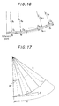
- Figs. 16 and 17 are views for illustrating the principle of the curvature comparison method.
- Fig. 16 shows the curve of the target shape (only its half to the right of M line, the reference line, is shown) divided into fine segments D 1 to D n which are arcs with radii of R 1 to R n .
- Fig. 17 shows a mode in which one of the divisional arcs indicated in Fig. 16 is approximated by a fold line defined by the bases of a plurality of (number m in Fig. 17) congruent isosceles triangles connected together while sharing their equal sides. As shown in Fig.
- the target shape is divided into a plurality of fine segments D 1 to D n , these fine segments D 1 to D n are regarded as arcs, curvatures or radii are designated for the respective segments D 1 to D n , and the lengths l 1 to l n of the arcs of the respective segments D 1 to D n are designated, whereby the target shape can be specified.
- the target shape data 12 in the respective segments D 1 to D n are compared with the steel plate measurement data 13, the amount of deformation of the steel plate 2 for making the target shape and the shape of the steel plate agree can be determined by the difference between the two types of data.
- the deformation in heat bending is bending at the heating points. That is, the arcs in the respective fine segments are approximated by straight lines.
- ⁇ is the angle between the bases of the isosceles triangles.
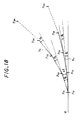
- Fig. 18 is an explanation drawing showing by a two-dot chain line a mode in which the arc of one segment of the target shape is approximated by a fold line N O defined by the bases of the m number of isosceles triangles connected together while sharing their equal sides, and showing by a solid line a mode in which the arc of one segment of the measured shape corresponding to this segment is approximated by a fold line N C defined by the bases of the m number of isosceles triangles connected together while sharing their equal sides.
- ⁇ O is the angle that each subline of the fold line N O forms with the adjacent subline
- ⁇ C is the angle that each subline of the fold line N C forms with the adjacent subline.
- the bending angle at this time is designated as ⁇
- the bending angle ⁇ is given as the difference between the angle formed by the adjacent sublines of the fold line N O and the angle formed by the adjacent sublines of the fold line N C .
- l 0 l C
- the amount of heating e.g., the amount of heat input based on parameters such as an electric current, and the clearance between a high frequency heating coil and the steel plate 2, during high frequency heating
- the heating points are obtained as respective positions found when the length l C is divided by the heating distance (l C /m). That is, if the radius R 0 of the arc of the target shape, the radius R c of the arc of the measured shape corresponding thereto, the length l 0 (length of the segment to be compared) of both arcs, and the bending angle ⁇ are given, then the three-dimensional positional coordinates of the corresponding heating points can be sought as solutions to geometrical problems by computations.
- the equation (7) is equal to calculating the number m of isosceles triangles for the length l 0 of the arc in the isosceles triangles which inscribe in the target shape with radius R 0 and whose adjacent bases form the angle ⁇ .
- the heating distance can be found from the radius R 0 of the target shape and the bending angle ⁇ .
- the heating point determining unit 11 prepares the following data on the basis of the target shape data 12 read in: 1 ⁇ position data on the reference line on each frame line, 2 ⁇ position data on the end of the steel plate 2 as the object to be processed, 3 ⁇ curvature data on the arc in each segment when the curved shape of the steel plate 2 on each frame line is regarded as a collection of arcs with a plurality of curvatures, and 4 ⁇ position data on the point of the boundary between each segment and the adjacent segment.
- the curvature data 3 ⁇ are values designated at the time of designing, or if these values are not designated, the data are calculated using the point sequence data of the target shape data 12.
- data corresponding to 1 ⁇ to 4 ⁇ are compiled from the steel plate shape measurement data 13 as well. At this time, the data 3 ⁇ correspond to the respective segments of the target shape.
- the heating point determining unit 11 processes the data 1 ⁇ to 4 ⁇ on the target shape and the measured shape, and calculates the heating points by the curvature comparison method described based on Figs. 16 to 18.
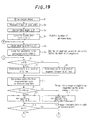
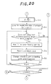
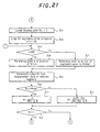
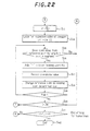
- An example of the relevant concrete procedure will be explained by reference to Figs. 19 to 22.
- Figs. 19 to 22 are flow charts showing this example.
- the heating points are obtained on the frame lines, but needless to say, the way of obtaining them is not restricted to this manner.
- the frame lines are lines corresponding to the positions at which frame materials are attached.
- data on their positions are stored as design data.
- the use of the frame lines in obtaining the heating points is advantageous in the applicability of such data.
- a concrete procedure using the heating line determining unit 14 for determining the heating lines based on the heating points that have been determined by the curvature comparison method is the same as that described in the flow charts for the aforementioned embodiment (Figs. 11 to 13). That is, the three-dimensional data on the heating points on the respective frame lines obtained at step S 19 of Fig. 20 and step S 37 of Fig. 22 are entered for "Enter sequence of heating points" at step S 21 of Fig. 11.
Landscapes
- Engineering & Computer Science (AREA)
- Mechanical Engineering (AREA)
- Length Measuring Devices With Unspecified Measuring Means (AREA)
- Bending Of Plates, Rods, And Pipes (AREA)
- Investigating Strength Of Materials By Application Of Mechanical Stress (AREA)
Claims (1)
- Verfahren zum Bestimmen eines Erwärmungspunktes beim Biegen einer Stahlplatte, die einem Vorbiegen unterzogen worden ist, wobei das Verfahren folgendes aufweist:Anordnen eines virtuellen Holzmusters, das aus Zielformdaten auf einer virtuellen Stahlplatte gebildet ist, die aus Stahlplattenformen-Meßdaten gebildet ist, wobei die Zielformdaten Daten auf einer Zielform der zu biegenden Stahlplatte sind, und wobei die Stahlplattenform-Meßdaten durch Messung einer Oberflächenform der Stahlplatte erhalten werden; Rollen des Holzmusters oder der Stahlplatte entlang einer spezifischen Linie auf der Stahlplatte, wie beispielsweise einer Rahmenlinie, von einer vorbestimmten Referenzposition in einer Ebene, die einen Querschnitt der Stahlplatte einschließt, um das Holzmuster und die Stahlplatte an zwei Punkten in Berührung zu bringen, wobei die Berührungspunkte auf der Stahlplatte als A, B und die Berührungspunkte auf dem Holzmuster als C, D bezeichnet werden;dann Rollen des Holzmusters oder der Stahlplatte in umgekehrter Richtung, um es/sie in die Referenzposition zurückzubringen; mit dem in die Referenzposition zurückgebrachten Holzmuster oder der in die Referenzposition zurückgebrachten Stahlplatte, Erhalten einer geraden Linie U, die die Berührungspunkte A, B verbindet, und einer geraden Linie V, die die Berührungspunkte C, D verbindet; und Bestimmen eines Erwärmungspunktes auf der Projektion eines Schnittpunktes P der geraden Linien U, V auf der Stahlplatte.
Applications Claiming Priority (12)
| Application Number | Priority Date | Filing Date | Title |
|---|---|---|---|
| JP263751/97 | 1997-09-29 | ||
| JP26375197 | 1997-09-29 | ||
| JP26374897 | 1997-09-29 | ||
| JP26375197 | 1997-09-29 | ||
| JP263748/97 | 1997-09-29 | ||
| JP26374897 | 1997-09-29 | ||
| JP26108998 | 1998-09-16 | ||
| JP26108898A JP3727784B2 (ja) | 1997-09-29 | 1998-09-16 | 鋼板曲げ加工における加熱点及び加熱線の決定方法及び装置 |
| JP261089/98 | 1998-09-16 | ||
| JP261088/98 | 1998-09-16 | ||
| JP26108898 | 1998-09-16 | ||
| JP26108998A JP3679932B2 (ja) | 1997-09-29 | 1998-09-16 | 鋼板曲げ加工における加熱点及び加熱線の決定方法及び装置 |
Publications (3)
| Publication Number | Publication Date |
|---|---|
| EP0904867A2 EP0904867A2 (de) | 1999-03-31 |
| EP0904867A3 EP0904867A3 (de) | 2000-08-02 |
| EP0904867B1 true EP0904867B1 (de) | 2002-04-10 |
Family
ID=27478569
Family Applications (1)
| Application Number | Title | Priority Date | Filing Date |
|---|---|---|---|
| EP98118299A Expired - Lifetime EP0904867B1 (de) | 1997-09-29 | 1998-09-28 | Verfahren und System zur Bestimmung des Heizpunktes und Heitzlinien im Biegeprozess einer Platte |
Country Status (6)
| Country | Link |
|---|---|
| US (3) | US6298310B1 (de) |
| EP (1) | EP0904867B1 (de) |
| KR (1) | KR100288414B1 (de) |
| DE (1) | DE69804735T2 (de) |
| DK (1) | DK0904867T3 (de) |
| NO (1) | NO312276B1 (de) |
Families Citing this family (16)
| Publication number | Priority date | Publication date | Assignee | Title |
|---|---|---|---|---|
| US6298310B1 (en) * | 1997-09-29 | 2001-10-02 | Mitsubishi Heavy Industries, Ltd. | Method and system for determining heating point and heating line in bending of steel plate |
| GB0119023D0 (en) * | 2001-08-03 | 2001-09-26 | Norsk Hydro As | Method and apparatus for distorting a workpiece |
| US6992756B1 (en) * | 2002-10-21 | 2006-01-31 | Og Technologies, Inc. | Apparatus and method for movement measurement and position tracking of long, non-textured metal objects at an elevated temperature |
| KR100911498B1 (ko) | 2007-05-30 | 2009-08-07 | 삼성중공업 주식회사 | 삼각가열 가열 형상 및 위치 결정시스템 및 그 방법 |
| US20150023387A1 (en) * | 2008-03-31 | 2015-01-22 | Jfe Steel Corporation | Steel plate quality assurance system and equipment thereof |
| US10231289B2 (en) | 2013-11-07 | 2019-03-12 | Illinois Tool Works Inc. | Large scale metal forming |
| US10112227B2 (en) | 2013-11-07 | 2018-10-30 | Illinois Tool Works Inc. | Large scale metal forming control system and method |
| CN104399792B (zh) * | 2014-11-28 | 2018-04-27 | 广东工业大学 | 一种基于朴素贝叶斯分类器的水火弯板焰道点判定方法 |
| CN105772551B (zh) * | 2016-01-29 | 2018-01-30 | 广东工业大学 | 一种基于切比雪夫不等式的水火弯板成形检测方法 |
| JP6859164B2 (ja) * | 2017-04-06 | 2021-04-14 | 川崎重工業株式会社 | 変形加工支援システムおよび変形加工支援方法 |
| CA2986676C (en) * | 2017-11-24 | 2020-01-07 | Bombardier Transportation Gmbh | Method for automated straightening of welded assemblies |
| KR102070160B1 (ko) * | 2019-07-24 | 2020-01-28 | 기득산업 주식회사 | 위치 제어 기능을 가진 판재 곡면 성형 시스템 및 그 방법 |
| KR102070155B1 (ko) * | 2019-07-24 | 2020-01-28 | 기득산업 주식회사 | 판재 곡면 성형 시스템 |
| KR102070158B1 (ko) * | 2019-07-24 | 2020-01-28 | 기득산업 주식회사 | 판재 곡면 성형 시스템 |
| KR102436323B1 (ko) * | 2021-04-30 | 2022-08-25 | 한국조선해양 주식회사 | 선체 곡 외판용 외종곡 형성시스템 |
| CN116689536A (zh) * | 2023-04-27 | 2023-09-05 | 中船黄埔文冲船舶有限公司 | 一种双曲铝制板的加工方法 |
Family Cites Families (12)
| Publication number | Priority date | Publication date | Assignee | Title |
|---|---|---|---|---|
| US4120187A (en) | 1977-05-24 | 1978-10-17 | General Dynamics Corporation | Forming curved segments from metal plates |
| JPH06541A (ja) * | 1992-06-17 | 1994-01-11 | Ishikawajima Harima Heavy Ind Co Ltd | 線状加熱装置 |
| EP0575646A1 (de) | 1992-06-22 | 1993-12-29 | Aliteco Ag | Verfahren und Vorrichtung zum Formen unterschiedlicher Werkstücke |
| JP2666674B2 (ja) * | 1993-01-29 | 1997-10-22 | 石川島播磨重工業株式会社 | 線状加熱による金属板の曲げ加工方法 |
| US5719374A (en) | 1993-03-25 | 1998-02-17 | Centrum Laserowych Technologii Metali Politechniki Swietokrzyskiej W Kielcach I Polskiej Akademii Nauk | Method of bending metal objects with an energy beam |
| JP2666685B2 (ja) * | 1993-07-12 | 1997-10-22 | 石川島播磨重工業株式会社 | 線状加熱による金属板の曲げ加工方法 |
| PL299688A3 (en) | 1993-07-15 | 1995-01-23 | Pan | Method of bending metal workpieces |
| JP2626496B2 (ja) * | 1993-08-26 | 1997-07-02 | 石川島播磨重工業株式会社 | 線状加熱による金属板の曲げ加工方法 |
| JP2666691B2 (ja) * | 1993-09-07 | 1997-10-22 | 石川島播磨重工業株式会社 | 線状加熱による金属板の曲げ加工方法 |
| JP3478891B2 (ja) * | 1995-01-11 | 2003-12-15 | 末弘 水河 | 帯刃の製造方法 |
| NO312446B1 (no) * | 1997-09-24 | 2002-05-13 | Mitsubishi Heavy Ind Ltd | Automatisk plateböyingssystem med bruk av höyfrekvent induksjonsoppvarming |
| US6298310B1 (en) * | 1997-09-29 | 2001-10-02 | Mitsubishi Heavy Industries, Ltd. | Method and system for determining heating point and heating line in bending of steel plate |
-
1998
- 1998-09-24 US US09/159,758 patent/US6298310B1/en not_active Expired - Fee Related
- 1998-09-28 NO NO19984529A patent/NO312276B1/no not_active IP Right Cessation
- 1998-09-28 KR KR1019980040341A patent/KR100288414B1/ko not_active Expired - Fee Related
- 1998-09-28 DE DE69804735T patent/DE69804735T2/de not_active Expired - Fee Related
- 1998-09-28 DK DK98118299T patent/DK0904867T3/da active
- 1998-09-28 EP EP98118299A patent/EP0904867B1/de not_active Expired - Lifetime
-
2001
- 2001-04-16 US US09/834,604 patent/US6385556B1/en not_active Expired - Fee Related
-
2002
- 2002-02-04 US US10/061,250 patent/US6456957B1/en not_active Expired - Fee Related
Also Published As
| Publication number | Publication date |
|---|---|
| DE69804735D1 (de) | 2002-05-16 |
| NO984529L (no) | 1999-03-30 |
| EP0904867A3 (de) | 2000-08-02 |
| NO312276B1 (no) | 2002-04-22 |
| US20020107656A1 (en) | 2002-08-08 |
| KR100288414B1 (ko) | 2001-05-02 |
| US6385556B1 (en) | 2002-05-07 |
| US20020032542A1 (en) | 2002-03-14 |
| KR19990030211A (ko) | 1999-04-26 |
| US6298310B1 (en) | 2001-10-02 |
| DE69804735T2 (de) | 2002-10-02 |
| NO984529D0 (no) | 1998-09-28 |
| EP0904867A2 (de) | 1999-03-31 |
| DK0904867T3 (da) | 2002-07-01 |
| US6456957B1 (en) | 2002-09-24 |
Similar Documents
| Publication | Publication Date | Title |
|---|---|---|
| EP0904867B1 (de) | Verfahren und System zur Bestimmung des Heizpunktes und Heitzlinien im Biegeprozess einer Platte | |
| EP0904866B1 (de) | Automatisches Platte-Biegesystem unter Verwendung von Hochfrequenz-Induktionsheizung | |
| EP0955105B1 (de) | Verfahren und vorrichtung zur bestimmung der biegereihenfolge in einer biegemaschine | |
| CN109883336B (zh) | 一种面向船舶曲面板材加工过程中的测量系统及测量方法 | |
| JP4585165B2 (ja) | 曲面を有する金属板の製造方法およびその製造装置並びに曲面を有する金属板 | |
| EP1747076B1 (de) | Verfahren und vorrichtung zur optimierung von schmiedeverfahren | |
| JPH06147863A (ja) | 曲げ加工機における曲げ角度検出装置 | |
| GB2325066A (en) | Generating and veryifying die shape data for making automobile body parts | |
| EP1921417A1 (de) | Vorrichtung und verfahren zur verzerrungsevaluierung | |
| CN117387487B (zh) | 一种利用自由放置单圆柱目标的结构光标定方法 | |
| JP3727784B2 (ja) | 鋼板曲げ加工における加熱点及び加熱線の決定方法及び装置 | |
| US7162398B2 (en) | Method for evaluating the dynamic perspective distortion of a transparent body and method for supporting the designing of a three-dimensionally curved shape of a transparent body | |
| JP2000237826A (ja) | 曲げ加工用金属板の展開形状選定方法 | |
| JPH11267869A (ja) | 溶接管の製造方法及び溶接管の製造装置 | |
| JP2002277236A (ja) | 公差判定方法 | |
| JP4252371B2 (ja) | 曲げ加工機における曲げ角度検出センサの位置決め配置方法および装置、並びに同曲げ角度検出センサを用いた曲げ加工機の制御方法 | |
| KR102735495B1 (ko) | 곡형 부재 제작 시스템 | |
| JPH10103921A (ja) | 光切断法によるワークの断面計測方法 | |
| JPH0639440A (ja) | アール曲げ加工データ作成方法 | |
| JP2908078B2 (ja) | 微小環状溝の深さ分布測定方法 | |
| JPH10232110A (ja) | 光切断法によるワーク計測方法 | |
| Mori et al. | INCREMENTAL HAMMERING FORMING OF SHEET METALAUTOMATED USING eco CAMERA AND DATABASE | |
| JPS62114812A (ja) | 鋼板の子板採取方法及びその装置 | |
| JPH11201746A (ja) | 姿見駒の形状デ−タ作成装置 |
Legal Events
| Date | Code | Title | Description |
|---|---|---|---|
| PUAI | Public reference made under article 153(3) epc to a published international application that has entered the european phase |
Free format text: ORIGINAL CODE: 0009012 |
|
| 17P | Request for examination filed |
Effective date: 19981026 |
|
| AK | Designated contracting states |
Kind code of ref document: A2 Designated state(s): DE DK FR GB IT NL |
|
| AX | Request for extension of the european patent |
Free format text: AL;LT;LV;MK;RO;SI |
|
| PUAL | Search report despatched |
Free format text: ORIGINAL CODE: 0009013 |
|
| RIC1 | Information provided on ipc code assigned before grant |
Free format text: 7B 21D 11/20 A, 7B 21D 5/00 B |
|
| AK | Designated contracting states |
Kind code of ref document: A3 Designated state(s): AT BE CH CY DE DK ES FI FR GB GR IE IT LI LU MC NL PT SE |
|
| AX | Request for extension of the european patent |
Free format text: AL;LT;LV;MK;RO;SI |
|
| 17Q | First examination report despatched |
Effective date: 20001204 |
|
| AKX | Designation fees paid |
Free format text: DE DK FR GB IT NL |
|
| GRAG | Despatch of communication of intention to grant |
Free format text: ORIGINAL CODE: EPIDOS AGRA |
|
| GRAG | Despatch of communication of intention to grant |
Free format text: ORIGINAL CODE: EPIDOS AGRA |
|
| GRAH | Despatch of communication of intention to grant a patent |
Free format text: ORIGINAL CODE: EPIDOS IGRA |
|
| GRAH | Despatch of communication of intention to grant a patent |
Free format text: ORIGINAL CODE: EPIDOS IGRA |
|
| REG | Reference to a national code |
Ref country code: GB Ref legal event code: IF02 |
|
| GRAA | (expected) grant |
Free format text: ORIGINAL CODE: 0009210 |
|
| AK | Designated contracting states |
Kind code of ref document: B1 Designated state(s): DE DK FR GB IT NL |
|
| REF | Corresponds to: |
Ref document number: 69804735 Country of ref document: DE Date of ref document: 20020516 |
|
| REG | Reference to a national code |
Ref country code: DK Ref legal event code: T3 |
|
| ET | Fr: translation filed | ||
| PLBE | No opposition filed within time limit |
Free format text: ORIGINAL CODE: 0009261 |
|
| STAA | Information on the status of an ep patent application or granted ep patent |
Free format text: STATUS: NO OPPOSITION FILED WITHIN TIME LIMIT |
|
| 26N | No opposition filed |
Effective date: 20030113 |
|
| PGFP | Annual fee paid to national office [announced via postgrant information from national office to epo] |
Ref country code: FR Payment date: 20030909 Year of fee payment: 6 |
|
| PGFP | Annual fee paid to national office [announced via postgrant information from national office to epo] |
Ref country code: DK Payment date: 20030915 Year of fee payment: 6 |
|
| PGFP | Annual fee paid to national office [announced via postgrant information from national office to epo] |
Ref country code: NL Payment date: 20030922 Year of fee payment: 6 |
|
| PGFP | Annual fee paid to national office [announced via postgrant information from national office to epo] |
Ref country code: GB Payment date: 20030924 Year of fee payment: 6 |
|
| PGFP | Annual fee paid to national office [announced via postgrant information from national office to epo] |
Ref country code: DE Payment date: 20031009 Year of fee payment: 6 |
|
| PG25 | Lapsed in a contracting state [announced via postgrant information from national office to epo] |
Ref country code: GB Free format text: LAPSE BECAUSE OF NON-PAYMENT OF DUE FEES Effective date: 20040928 |
|
| PG25 | Lapsed in a contracting state [announced via postgrant information from national office to epo] |
Ref country code: DK Free format text: LAPSE BECAUSE OF NON-PAYMENT OF DUE FEES Effective date: 20040930 |
|
| PG25 | Lapsed in a contracting state [announced via postgrant information from national office to epo] |
Ref country code: NL Free format text: LAPSE BECAUSE OF NON-PAYMENT OF DUE FEES Effective date: 20050401 Ref country code: DE Free format text: LAPSE BECAUSE OF NON-PAYMENT OF DUE FEES Effective date: 20050401 |
|
| GBPC | Gb: european patent ceased through non-payment of renewal fee |
Effective date: 20040928 |
|
| PG25 | Lapsed in a contracting state [announced via postgrant information from national office to epo] |
Ref country code: FR Free format text: LAPSE BECAUSE OF NON-PAYMENT OF DUE FEES Effective date: 20050531 |
|
| NLV4 | Nl: lapsed or anulled due to non-payment of the annual fee |
Effective date: 20050401 |
|
| REG | Reference to a national code |
Ref country code: DK Ref legal event code: EBP |
|
| REG | Reference to a national code |
Ref country code: FR Ref legal event code: ST |
|
| PG25 | Lapsed in a contracting state [announced via postgrant information from national office to epo] |
Ref country code: IT Free format text: LAPSE BECAUSE OF NON-PAYMENT OF DUE FEES Effective date: 20050928 |