EP0904791B1 - Dispositif pour inhalation - Google Patents
Dispositif pour inhalation Download PDFInfo
- Publication number
- EP0904791B1 EP0904791B1 EP98118086A EP98118086A EP0904791B1 EP 0904791 B1 EP0904791 B1 EP 0904791B1 EP 98118086 A EP98118086 A EP 98118086A EP 98118086 A EP98118086 A EP 98118086A EP 0904791 B1 EP0904791 B1 EP 0904791B1
- Authority
- EP
- European Patent Office
- Prior art keywords
- container
- inhaler according
- heating element
- thick
- film resistor
- Prior art date
- Legal status (The legal status is an assumption and is not a legal conclusion. Google has not performed a legal analysis and makes no representation as to the accuracy of the status listed.)
- Expired - Lifetime
Links
Images


Classifications
-
- H—ELECTRICITY
- H05—ELECTRIC TECHNIQUES NOT OTHERWISE PROVIDED FOR
- H05B—ELECTRIC HEATING; ELECTRIC LIGHT SOURCES NOT OTHERWISE PROVIDED FOR; CIRCUIT ARRANGEMENTS FOR ELECTRIC LIGHT SOURCES, IN GENERAL
- H05B3/00—Ohmic-resistance heating
- H05B3/20—Heating elements having extended surface area substantially in a two-dimensional [2D] plane, e.g. plate-heater
- H05B3/22—Heating elements having extended surface area substantially in a two-dimensional [2D] plane, e.g. plate-heater non-flexible
- H05B3/26—Heating elements having extended surface area substantially in a two-dimensional [2D] plane, e.g. plate-heater non-flexible heating conductor mounted on insulating base
-
- A—HUMAN NECESSITIES
- A61—MEDICAL OR VETERINARY SCIENCE; HYGIENE
- A61M—DEVICES FOR INTRODUCING MEDIA INTO, OR ONTO, THE BODY; DEVICES FOR TRANSDUCING BODY MEDIA OR FOR TAKING MEDIA FROM THE BODY; DEVICES FOR PRODUCING OR ENDING SLEEP OR STUPOR
- A61M11/00—Sprayers or atomisers specially adapted for therapeutic purposes
- A61M11/04—Sprayers or atomisers specially adapted for therapeutic purposes operated by the vapour pressure of the liquid to be sprayed or atomised
- A61M11/041—Sprayers or atomisers specially adapted for therapeutic purposes operated by the vapour pressure of the liquid to be sprayed or atomised using heaters
- A61M11/042—Sprayers or atomisers specially adapted for therapeutic purposes operated by the vapour pressure of the liquid to be sprayed or atomised using heaters electrical
-
- A—HUMAN NECESSITIES
- A61—MEDICAL OR VETERINARY SCIENCE; HYGIENE
- A61M—DEVICES FOR INTRODUCING MEDIA INTO, OR ONTO, THE BODY; DEVICES FOR TRANSDUCING BODY MEDIA OR FOR TAKING MEDIA FROM THE BODY; DEVICES FOR PRODUCING OR ENDING SLEEP OR STUPOR
- A61M15/00—Inhalators
-
- A—HUMAN NECESSITIES
- A61—MEDICAL OR VETERINARY SCIENCE; HYGIENE
- A61M—DEVICES FOR INTRODUCING MEDIA INTO, OR ONTO, THE BODY; DEVICES FOR TRANSDUCING BODY MEDIA OR FOR TAKING MEDIA FROM THE BODY; DEVICES FOR PRODUCING OR ENDING SLEEP OR STUPOR
- A61M2205/00—General characteristics of the apparatus
- A61M2205/36—General characteristics of the apparatus related to heating or cooling
- A61M2205/3653—General characteristics of the apparatus related to heating or cooling by Joule effect, i.e. electric resistance
-
- H—ELECTRICITY
- H05—ELECTRIC TECHNIQUES NOT OTHERWISE PROVIDED FOR
- H05B—ELECTRIC HEATING; ELECTRIC LIGHT SOURCES NOT OTHERWISE PROVIDED FOR; CIRCUIT ARRANGEMENTS FOR ELECTRIC LIGHT SOURCES, IN GENERAL
- H05B2203/00—Aspects relating to Ohmic resistive heating covered by group H05B3/00
- H05B2203/002—Heaters using a particular layout for the resistive material or resistive elements
- H05B2203/003—Heaters using a particular layout for the resistive material or resistive elements using serpentine layout
-
- H—ELECTRICITY
- H05—ELECTRIC TECHNIQUES NOT OTHERWISE PROVIDED FOR
- H05B—ELECTRIC HEATING; ELECTRIC LIGHT SOURCES NOT OTHERWISE PROVIDED FOR; CIRCUIT ARRANGEMENTS FOR ELECTRIC LIGHT SOURCES, IN GENERAL
- H05B2203/00—Aspects relating to Ohmic resistive heating covered by group H05B3/00
- H05B2203/002—Heaters using a particular layout for the resistive material or resistive elements
- H05B2203/004—Heaters using a particular layout for the resistive material or resistive elements using zigzag layout
-
- H—ELECTRICITY
- H05—ELECTRIC TECHNIQUES NOT OTHERWISE PROVIDED FOR
- H05B—ELECTRIC HEATING; ELECTRIC LIGHT SOURCES NOT OTHERWISE PROVIDED FOR; CIRCUIT ARRANGEMENTS FOR ELECTRIC LIGHT SOURCES, IN GENERAL
- H05B2203/00—Aspects relating to Ohmic resistive heating covered by group H05B3/00
- H05B2203/013—Heaters using resistive films or coatings
-
- H—ELECTRICITY
- H05—ELECTRIC TECHNIQUES NOT OTHERWISE PROVIDED FOR
- H05B—ELECTRIC HEATING; ELECTRIC LIGHT SOURCES NOT OTHERWISE PROVIDED FOR; CIRCUIT ARRANGEMENTS FOR ELECTRIC LIGHT SOURCES, IN GENERAL
- H05B2203/00—Aspects relating to Ohmic resistive heating covered by group H05B3/00
- H05B2203/017—Manufacturing methods or apparatus for heaters
-
- H—ELECTRICITY
- H05—ELECTRIC TECHNIQUES NOT OTHERWISE PROVIDED FOR
- H05B—ELECTRIC HEATING; ELECTRIC LIGHT SOURCES NOT OTHERWISE PROVIDED FOR; CIRCUIT ARRANGEMENTS FOR ELECTRIC LIGHT SOURCES, IN GENERAL
- H05B2203/00—Aspects relating to Ohmic resistive heating covered by group H05B3/00
- H05B2203/021—Heaters specially adapted for heating liquids
Definitions
- the present invention relates to a Inhalation device with a container for receiving a liquid and an electric heating element that is in heat-conducting contact with the container for Heating a liquid received in the container.
- Various treatments are used to treat respiratory diseases Inhalers, such as nebulizers, Atomizers and inhalers used.
- Inhalers such as nebulizers, Atomizers and inhalers used.
- By means of such Apparatuses are fine therapeutic agents distributed form inhaled by a patient.
- the rule is heating that is usually in liquid or active ingredients in dissolved form.
- an atomizer for Nebulization of liquid or solid substances for Inhalation is provided.
- the well-known atomizer has a container and a separate electrical Heating element that is in heat-conducting contact with the Container stands.
- a PCT thermistor serves as the heating element, in a body with high thermal conductivity is arranged. This body is typically a Metal block, and partially surrounds the container. Thereby is a good thermal coupling between the heating element and Guaranteed container, and heating the container takes place directly by heating the metal block.
- a nebulizer equipped with it has large ones Dimensions due to the heat transfer from Heating element on container necessary metal block a lot of space claimed.
- the entire device is therefore globular and unwieldy, and can only be used as a tabletop device.
- Another disadvantage is the high heating power is needed around the temperature of the metal block, and thus the temperature of the one in the container Liquid to control via the PCT thermistor.
- the Temperature control is also extreme sluggish because the entire metal block has to be heated or the cooling of the metal block is very slow.
- the present invention therefore has the problem to provide an inhalation device that much smaller dimensions than previously known Has devices, and thus particularly is user-friendly.
- a central idea of the invention is that the container made of a ceramic with a There is thermal conductivity ⁇ > 15 W / km, and that Heating element in the form of a thick film resistor arranged directly on the outside of the container bottom is.
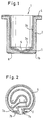
- Fig. 1 shows a sectional view of the in Inhalation device used according to the invention Container 1.
- the container 1 has a cylindrical Side wall 2 with constant wall thickness and is on one Ended with a circular bottom 3.
- the Inside 3a of the bottom 3 is designed so that it ' tapers towards the central region 5 of the base 3. Consequently the thickness of the bottom 3 decreases towards the center.
- the liquid in the container flows automatically in the middle of the container bottom.
- Such Design is special when using the Container in nebulizers advantageous because here over a Atomizer nozzle perpendicular to the central area 5 is arranged, and which in the in the container immersed liquid, the liquid from the Cup is sucked.
- a Heating element 6 in the form of a thick film resistor arranged on the outer surface 3b of the bottom 3 .
- the thick film resistance is by means of Screen printing process on the polished and flat ground outer bottom surface 3b of the container 1 printed and then burned in.
- the resistance of the Dickschit resistance is typically about 12 Ohm.
- the design of the heating element 6 on the The outer bottom surface 3b of the container 1 is shown in FIG. 2 out.
- the two ends of the heating element are as Connections 7a and 7b to the outer edge of the Outside floor surface 3b led out.
- the heating element 6 extends in a straight line from the connecting element 7a in Towards the central area of the floor surface, up to that in Fig. 2 with A point.
- the heating element 6 kinks here at an angle of 90 ° towards the bottom edge, and extends up to that designated B in FIG. 2 Point.
- the heating element describes from point B to point C. a circular path, counterclockwise along the Edges of the outer floor surface and sweeps to point C an angle of approximately 320 °.
- At point C kinks the heating element at an angle of approximately 45 ° in the direction of central area 5, and then runs from Point D to point E parallel to that from point A to point B. trending straight area of the heating element. From point E on the heating element sweeps circularly Surrounding central region 5, an angle of approximately 270 °. At point F the direction of rotation of the Heating element around (now clockwise) and sweeps up to Point G has an angular range of approximately 300 °. In point G kinks the heating element, so that the range from G to H runs parallel to the area A to B or E to D. In Point H then bends the heating element 90 ° in the direction of second pad 7b to connect to this to kick.
- Such a heating element causes an even distribution of heating power on the liquid in the container. It should also be mentioned that the central region 5 is not covered by the heating element is because this area of the floor area, as mentioned before, has a reduced thickness and is therefore more sensitive than that remaining area of the bottom 3. By leaving out the Middle area 5 will overheat the thin one Avoided floor area.
- the arrangement of the heating element is not based on that arrangement described above limited. Instead, can the heating element also spiral, - meander or wavy be trained. Also a zigzag shape or other shapes are possible.
- the one in the inhalation device according to the invention The container is made of an alumina ceramic produced by injection molding.
- the one used Ceramic has a thermal conductivity, which in the Order of magnitude of the thermal conductivity of stainless steel; According to the invention, the thermal conductivity of the used Ceramics can be larger than 15 W / km. This grants one sufficient heat transfer to the one to be heated Liquid.
- a container diameter of for example 34 mm with a container height of 36.5 mm and a wall thickness of typically 2 mm proves to be suitable.
- the ratio of Container wall thickness to container height between 1:16 and 1:20 lie, and the ratio of container wall thickness to Container diameters are between 1:15 and 1:19.
- the inside of the container i.e. Glaze the inside surface 2a and the inside surface 3a. This avoids that in the container liquids in the wall surface of the container penetrate, or they discolor the wall surfaces. This is when used in therapeutic inhalation devices important because of the existing hygiene requirements thorough cleaning of the container is necessary, and Active substance residues in the container should be avoided.
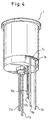
- FIG Regulation of the heating element can be entered.
- the container 1 on an insulating washer 8 arranged.
- the insulating washer 8 can also on the Be glued to the outer bottom surface of the container.
- the Insulating washer consists, for example, of "steatite” (Soapstone) or another suitable ceramic. A Alumina ceramic can also be used.
- the Insulating washer 8 has essentially the same diameter like the bottom 3 of the container, but has a side flattened area.
- the container is regarding the Insulating washer 8 arranged such that the contact surfaces 7a and 7b of the heating element 6 over the flattened area protrude the insulating washer 8.
- connection lines 9a and 9b via which the heating element with Power is supplied, past the insulating washer 8 and can directly with contact surfaces 7a and 7b in Get in touch.
- the other ends of the connecting line 9a and 9b are with an energy source (not shown) connected, which is preferably a 24V AC protective low voltage provides.
- an energy source (not shown) connected, which is preferably a 24V AC protective low voltage provides.
- Temperature sensors 10a and 10b serving NTC resistors introduced so that they with the container bottom 3 in Contact to immediately see the temperature of the To be able to measure the bottom of the container.
- Temperature limiter 11 comprising feed lines 11a and 11b, integrated into the insulation layer.
- the temperature limiter 11 causes the power supply through the Connecting lines 9a and 9b are automatically switched off, if the temperature sensors (NTC resistors) 10a and 10b record a maximum limit. If that's from the NTC resistors sensed temperature below a minimum Limit value drops, the temperature limiter 11 switches on Power supply to the heating element 6 automatically.
- the Arrangement of temperature limiter 11, temperature sensor 10a and 10b and power lines 9a and 9b go from FIGS. 4 and 5 out.
Landscapes
- Health & Medical Sciences (AREA)
- Engineering & Computer Science (AREA)
- Anesthesiology (AREA)
- Biomedical Technology (AREA)
- Heart & Thoracic Surgery (AREA)
- Hematology (AREA)
- Life Sciences & Earth Sciences (AREA)
- Animal Behavior & Ethology (AREA)
- General Health & Medical Sciences (AREA)
- Public Health (AREA)
- Veterinary Medicine (AREA)
- Thermotherapy And Cooling Therapy Devices (AREA)
- Resistance Heating (AREA)
- Weting (AREA)
- Investigating Or Analyzing Materials By The Use Of Fluid Adsorption Or Reactions (AREA)
- Surface Heating Bodies (AREA)
- Medical Preparation Storing Or Oral Administration Devices (AREA)
Claims (16)
- Dispositif pour inhalation comportant un récipient (1) devant recevoir un liquide et un élément chauffant (6) électrique, mis en contact conducteur de la chaleur avec le récipient (1) afin de chauffer le liquide se trouvant dans le récipient (1), caractérisé en ce que le récipient (1) est formé d'une céramique dont la conductivité thermique λ > 15 W/K.m et l'élément chauffant (6) est une résistance à couche épaisse, disposée sur la surface extérieure du récipient (1).
- Dispositif d'inhalation selon la revendication 1, caractérisé en ce que le récipient (1) est formé d'une céramique à base d'oxyde d'aluminium.
- Dispositif selon les revendications 1 et 2, caractérisé en ce que les faces intérieures du récipient (2a, 3a) sont émaillées.
- Dispositif selon l'une des revendications précédentes, caractérisé en ce que le récipient (1) présente une face de fond intérieure (3a) inclinée vers le centre.
- Dispositif selon l'une des revendications précédentes, caractérisé en ce que la face de fond extérieure (3b) du récipient est soumise à un usinage meulage l'ayant rendue plane.
- Dispositif selon l'une des revendications précédentes, caractérisé en ce que le rapport, entre l'épaisseur de la paroi du récipient et la hauteur du récipient, est compris dans la plage allant de 1:16 à 1:20.
- Dispositif selon l'une des revendications précédentes, caractérisé en ce que le rapport, entre l'épaisseur de paroi de récipient et le diamètre de récipient, est compris dans la plage allant de 1:15 à 1:19.
- Dispositif selon l'une des revendications précédentes, caractérisé en ce que la résistance à couche épaisse n'est disposée que sur une face inférieure extérieure (3b) du récipient.
- Dispositif selon l'une des revendications précédentes, caractérisé en ce que la résistance à couche épaisse est réalisée en forme de cercle, en forme de spirale, en forme de méandre ou en forme d'ondulation, ou bien présente une forme en zigzag.
- Dispositif selon l'une des revendications précédentes, caractérisé en ce que la zone centrale (5) de la face de fond du récipient n'est pas couverte par la résistance à couche épaisse.
- Dispositif selon l'une des revendications précédentes, caractérisé en ce que la résistance à couche épaisse présente une valeur de résistance électrique d'environ 12 Ω.
- Dispositif selon l'une des revendications précédentes, caractérisé en ce qu'est prévu un corps isolant, collé sur la face de fond extérieur du récipient et dans lequel est disposée une pluralité de sondes de température (10, 11).
- Dispositif selon la revendication 12, caractérisé en ce que les sondes de température disposées dans le corps isolant sont des résistances à caractéristique NTC (10).
- Dispositif selon la revendication 12, caractérisé en ce qu'est prévu un limiteur de température (11).
- Dispositif selon la revendication 12, caractérisé en ce que le corps isolant (8) est réalisé en céramique ou en stéatique.
- Dispositif selon l'une des revendications précédentes, caractérisé en ce que l'élément chauffant (6) est relié à une basse tension de protection de courant alternatif AC d'une valeur de 24 Volts, par l'intermédiaire des lignes de raccordement (9a, 9b).
Applications Claiming Priority (2)
| Application Number | Priority Date | Filing Date | Title |
|---|---|---|---|
| DE19742206 | 1997-09-24 | ||
| DE19742206A DE19742206A1 (de) | 1997-09-24 | 1997-09-24 | Inhalationsvorrichtung |
Publications (3)
| Publication Number | Publication Date |
|---|---|
| EP0904791A2 EP0904791A2 (fr) | 1999-03-31 |
| EP0904791A3 EP0904791A3 (fr) | 2000-01-12 |
| EP0904791B1 true EP0904791B1 (fr) | 2003-12-03 |
Family
ID=7843511
Family Applications (1)
| Application Number | Title | Priority Date | Filing Date |
|---|---|---|---|
| EP98118086A Expired - Lifetime EP0904791B1 (fr) | 1997-09-24 | 1998-09-24 | Dispositif pour inhalation |
Country Status (3)
| Country | Link |
|---|---|
| EP (1) | EP0904791B1 (fr) |
| AT (1) | ATE255440T1 (fr) |
| DE (2) | DE19742206A1 (fr) |
Families Citing this family (2)
| Publication number | Priority date | Publication date | Assignee | Title |
|---|---|---|---|---|
| GB0103658D0 (en) * | 2001-02-14 | 2001-03-28 | Strix Ltd | Electric beverage maker |
| GB0126150D0 (en) * | 2001-10-31 | 2002-01-02 | Gw Pharma Ltd | A device method and resistive element for vaporising a substance |
Family Cites Families (6)
| Publication number | Priority date | Publication date | Assignee | Title |
|---|---|---|---|---|
| DE3043537A1 (de) | 1980-11-18 | 1982-07-08 | Brugger, Inge, 8130 Starnberg | Zerstaeuber, insbesondere zu inhalationszwecken |
| US4819625A (en) * | 1987-11-12 | 1989-04-11 | Cimco, Inc. | Nebulizer heater |
| JPH01117355U (fr) * | 1988-01-28 | 1989-08-08 | ||
| JPH01194282A (ja) * | 1988-01-28 | 1989-08-04 | Ngk Insulators Ltd | セラミック・ヒータ及び電気化学的素子並びに酸素分析装置 |
| US5093894A (en) * | 1989-12-01 | 1992-03-03 | Philip Morris Incorporated | Electrically-powered linear heating element |
| US5408574A (en) * | 1989-12-01 | 1995-04-18 | Philip Morris Incorporated | Flat ceramic heater having discrete heating zones |
-
1997
- 1997-09-24 DE DE19742206A patent/DE19742206A1/de not_active Withdrawn
-
1998
- 1998-09-24 DE DE59810319T patent/DE59810319D1/de not_active Expired - Lifetime
- 1998-09-24 AT AT98118086T patent/ATE255440T1/de not_active IP Right Cessation
- 1998-09-24 EP EP98118086A patent/EP0904791B1/fr not_active Expired - Lifetime
Also Published As
| Publication number | Publication date |
|---|---|
| DE19742206A1 (de) | 1999-04-22 |
| DE59810319D1 (de) | 2004-01-15 |
| EP0904791A2 (fr) | 1999-03-31 |
| ATE255440T1 (de) | 2003-12-15 |
| EP0904791A3 (fr) | 2000-01-12 |
Similar Documents
| Publication | Publication Date | Title |
|---|---|---|
| DE69011523T2 (de) | Temperaturregelung von einer geheizten probe. | |
| DE602004004528T2 (de) | Einrichtung zur erwärmung einer flüssigkeit für ein haushaltsgerät, mit der einrichtung ausgestattetes haushaltsgerät | |
| US6253104B1 (en) | Method of preparing pharmaceutical Moxa extract and apparatus for electrical moxibustion using the same extract | |
| DE2919763A1 (de) | Zerstaeuberbrenner fuer oelfeuerungsanlagen | |
| EP0564953B1 (fr) | Dispositif de chauffage pour appareil d'insufflation | |
| DE3311811A1 (de) | Vorrichtung zum behandeln der atmungswege mit warmluft | |
| EP4588377A1 (fr) | Ensemble de chauffage et dispositif de génération d'aérosol | |
| EP0904791B1 (fr) | Dispositif pour inhalation | |
| EP1197237A2 (fr) | Appareil respiratoire et méthode de commande | |
| WO2003055555A1 (fr) | Evaporateur pour appareils respiratoires et procede d'evaporation | |
| DE3027932A1 (de) | Fluessigkeitsstandfuehler. | |
| DE10341433A1 (de) | Beheizbarer Infrarot-Sensor und Infrarot-Thermometer mit einem derartigen Infrarot-Sensor | |
| DE69814877T2 (de) | Elektrischer flussigkeitsheizvorrichtung | |
| DE60131255T2 (de) | Temperatursensor | |
| WO1994028959A9 (fr) | Inhalateur | |
| DE3043537C2 (fr) | ||
| DE4331559A1 (de) | Vorrichtung zur Erwärmung von strömenden Medien | |
| EP0441193B1 (fr) | Dispositif de mesure pour déterminer la tendence pour transpirer de l'homme | |
| DE2109470C3 (de) | Elektrischer Lötkolben | |
| DE2659454C3 (de) | Gerät zur Wärmebehandlung | |
| DE69918453T2 (de) | Medizinisches thermometer | |
| DE3924764C1 (en) | Mouth mirror with electrical resistance heating surface - comprises mirror surface with rhodium coating electrically contacted with metallic conducting bands | |
| DE4031081C2 (de) | Sensoreinheit für ein Gerät zum Sieden von Flüssigkeit | |
| DE3612476C2 (fr) | ||
| DE3005401A1 (de) | Mundspiegel |
Legal Events
| Date | Code | Title | Description |
|---|---|---|---|
| PUAI | Public reference made under article 153(3) epc to a published international application that has entered the european phase |
Free format text: ORIGINAL CODE: 0009012 |
|
| AK | Designated contracting states |
Kind code of ref document: A2 Designated state(s): AT CH DE LI |
|
| AX | Request for extension of the european patent |
Free format text: AL;LT;LV;MK;RO;SI |
|
| PUAL | Search report despatched |
Free format text: ORIGINAL CODE: 0009013 |
|
| AK | Designated contracting states |
Kind code of ref document: A3 Designated state(s): AT BE CH CY DE DK ES FI FR GB GR IE IT LI LU MC NL PT SE |
|
| AX | Request for extension of the european patent |
Free format text: AL;LT;LV;MK;RO;SI |
|
| 17P | Request for examination filed |
Effective date: 20000308 |
|
| AKX | Designation fees paid |
Free format text: AT CH DE LI |
|
| GRAH | Despatch of communication of intention to grant a patent |
Free format text: ORIGINAL CODE: EPIDOS IGRA |
|
| GRAS | Grant fee paid |
Free format text: ORIGINAL CODE: EPIDOSNIGR3 |
|
| GRAA | (expected) grant |
Free format text: ORIGINAL CODE: 0009210 |
|
| AK | Designated contracting states |
Kind code of ref document: B1 Designated state(s): AT CH DE LI |
|
| REG | Reference to a national code |
Ref country code: CH Ref legal event code: EP |
|
| REF | Corresponds to: |
Ref document number: 59810319 Country of ref document: DE Date of ref document: 20040115 Kind code of ref document: P |
|
| PG25 | Lapsed in a contracting state [announced via postgrant information from national office to epo] |
Ref country code: AT Free format text: LAPSE BECAUSE OF NON-PAYMENT OF DUE FEES Effective date: 20040924 |
|
| PG25 | Lapsed in a contracting state [announced via postgrant information from national office to epo] |
Ref country code: LI Free format text: LAPSE BECAUSE OF NON-PAYMENT OF DUE FEES Effective date: 20040930 Ref country code: CH Free format text: LAPSE BECAUSE OF NON-PAYMENT OF DUE FEES Effective date: 20040930 |
|
| PLBE | No opposition filed within time limit |
Free format text: ORIGINAL CODE: 0009261 |
|
| STAA | Information on the status of an ep patent application or granted ep patent |
Free format text: STATUS: NO OPPOSITION FILED WITHIN TIME LIMIT |
|
| 26N | No opposition filed |
Effective date: 20040906 |
|
| REG | Reference to a national code |
Ref country code: CH Ref legal event code: PL |
|
| PGFP | Annual fee paid to national office [announced via postgrant information from national office to epo] |
Ref country code: DE Payment date: 20130924 Year of fee payment: 16 |
|
| REG | Reference to a national code |
Ref country code: DE Ref legal event code: R119 Ref document number: 59810319 Country of ref document: DE |
|
| REG | Reference to a national code |
Ref country code: DE Ref legal event code: R119 Ref document number: 59810319 Country of ref document: DE Effective date: 20150401 |
|
| PG25 | Lapsed in a contracting state [announced via postgrant information from national office to epo] |
Ref country code: DE Free format text: LAPSE BECAUSE OF NON-PAYMENT OF DUE FEES Effective date: 20150401 |