EP0904791B1 - Inhalation device - Google Patents
Inhalation device Download PDFInfo
- Publication number
- EP0904791B1 EP0904791B1 EP98118086A EP98118086A EP0904791B1 EP 0904791 B1 EP0904791 B1 EP 0904791B1 EP 98118086 A EP98118086 A EP 98118086A EP 98118086 A EP98118086 A EP 98118086A EP 0904791 B1 EP0904791 B1 EP 0904791B1
- Authority
- EP
- European Patent Office
- Prior art keywords
- container
- inhaler according
- heating element
- thick
- film resistor
- Prior art date
- Legal status (The legal status is an assumption and is not a legal conclusion. Google has not performed a legal analysis and makes no representation as to the accuracy of the status listed.)
- Expired - Lifetime
Links
- 239000000919 ceramic Substances 0.000 claims abstract description 10
- 238000010438 heat treatment Methods 0.000 claims description 39
- 239000007788 liquid Substances 0.000 claims description 16
- PNEYBMLMFCGWSK-UHFFFAOYSA-N Alumina Chemical compound [O-2].[O-2].[O-2].[Al+3].[Al+3] PNEYBMLMFCGWSK-UHFFFAOYSA-N 0.000 claims description 5
- 238000005485 electric heating Methods 0.000 claims description 2
- 230000001681 protective effect Effects 0.000 claims description 2
- 239000012212 insulator Substances 0.000 abstract 1
- TWNQGVIAIRXVLR-UHFFFAOYSA-N oxo(oxoalumanyloxy)alumane Chemical compound O=[Al]O[Al]=O TWNQGVIAIRXVLR-UHFFFAOYSA-N 0.000 abstract 1
- 239000002184 metal Substances 0.000 description 7
- 238000000034 method Methods 0.000 description 4
- 239000004480 active ingredient Substances 0.000 description 1
- 239000013543 active substance Substances 0.000 description 1
- 230000033228 biological regulation Effects 0.000 description 1
- 238000004140 cleaning Methods 0.000 description 1
- 238000001816 cooling Methods 0.000 description 1
- 230000008878 coupling Effects 0.000 description 1
- 238000010168 coupling process Methods 0.000 description 1
- 238000005859 coupling reaction Methods 0.000 description 1
- 238000005336 cracking Methods 0.000 description 1
- 230000007423 decrease Effects 0.000 description 1
- 230000001419 dependent effect Effects 0.000 description 1
- 238000009826 distribution Methods 0.000 description 1
- 239000003814 drug Substances 0.000 description 1
- 238000001746 injection moulding Methods 0.000 description 1
- 238000009413 insulation Methods 0.000 description 1
- 238000004519 manufacturing process Methods 0.000 description 1
- 238000002663 nebulization Methods 0.000 description 1
- 239000006199 nebulizer Substances 0.000 description 1
- 208000023504 respiratory system disease Diseases 0.000 description 1
- 238000007650 screen-printing Methods 0.000 description 1
- 239000007787 solid Substances 0.000 description 1
- 229910001220 stainless steel Inorganic materials 0.000 description 1
- 239000010935 stainless steel Substances 0.000 description 1
- 239000000126 substance Substances 0.000 description 1
- 229940124597 therapeutic agent Drugs 0.000 description 1
- 230000001225 therapeutic effect Effects 0.000 description 1
- 230000007704 transition Effects 0.000 description 1
- 238000011282 treatment Methods 0.000 description 1
Images


Classifications
-
- H—ELECTRICITY
- H05—ELECTRIC TECHNIQUES NOT OTHERWISE PROVIDED FOR
- H05B—ELECTRIC HEATING; ELECTRIC LIGHT SOURCES NOT OTHERWISE PROVIDED FOR; CIRCUIT ARRANGEMENTS FOR ELECTRIC LIGHT SOURCES, IN GENERAL
- H05B3/00—Ohmic-resistance heating
- H05B3/20—Heating elements having extended surface area substantially in a two-dimensional plane, e.g. plate-heater
- H05B3/22—Heating elements having extended surface area substantially in a two-dimensional plane, e.g. plate-heater non-flexible
- H05B3/26—Heating elements having extended surface area substantially in a two-dimensional plane, e.g. plate-heater non-flexible heating conductor mounted on insulating base
-
- A—HUMAN NECESSITIES
- A61—MEDICAL OR VETERINARY SCIENCE; HYGIENE
- A61M—DEVICES FOR INTRODUCING MEDIA INTO, OR ONTO, THE BODY; DEVICES FOR TRANSDUCING BODY MEDIA OR FOR TAKING MEDIA FROM THE BODY; DEVICES FOR PRODUCING OR ENDING SLEEP OR STUPOR
- A61M11/00—Sprayers or atomisers specially adapted for therapeutic purposes
- A61M11/04—Sprayers or atomisers specially adapted for therapeutic purposes operated by the vapour pressure of the liquid to be sprayed or atomised
- A61M11/041—Sprayers or atomisers specially adapted for therapeutic purposes operated by the vapour pressure of the liquid to be sprayed or atomised using heaters
- A61M11/042—Sprayers or atomisers specially adapted for therapeutic purposes operated by the vapour pressure of the liquid to be sprayed or atomised using heaters electrical
-
- A—HUMAN NECESSITIES
- A61—MEDICAL OR VETERINARY SCIENCE; HYGIENE
- A61M—DEVICES FOR INTRODUCING MEDIA INTO, OR ONTO, THE BODY; DEVICES FOR TRANSDUCING BODY MEDIA OR FOR TAKING MEDIA FROM THE BODY; DEVICES FOR PRODUCING OR ENDING SLEEP OR STUPOR
- A61M15/00—Inhalators
-
- A—HUMAN NECESSITIES
- A61—MEDICAL OR VETERINARY SCIENCE; HYGIENE
- A61M—DEVICES FOR INTRODUCING MEDIA INTO, OR ONTO, THE BODY; DEVICES FOR TRANSDUCING BODY MEDIA OR FOR TAKING MEDIA FROM THE BODY; DEVICES FOR PRODUCING OR ENDING SLEEP OR STUPOR
- A61M2205/00—General characteristics of the apparatus
- A61M2205/36—General characteristics of the apparatus related to heating or cooling
- A61M2205/3653—General characteristics of the apparatus related to heating or cooling by Joule effect, i.e. electric resistance
-
- H—ELECTRICITY
- H05—ELECTRIC TECHNIQUES NOT OTHERWISE PROVIDED FOR
- H05B—ELECTRIC HEATING; ELECTRIC LIGHT SOURCES NOT OTHERWISE PROVIDED FOR; CIRCUIT ARRANGEMENTS FOR ELECTRIC LIGHT SOURCES, IN GENERAL
- H05B2203/00—Aspects relating to Ohmic resistive heating covered by group H05B3/00
- H05B2203/002—Heaters using a particular layout for the resistive material or resistive elements
- H05B2203/003—Heaters using a particular layout for the resistive material or resistive elements using serpentine layout
-
- H—ELECTRICITY
- H05—ELECTRIC TECHNIQUES NOT OTHERWISE PROVIDED FOR
- H05B—ELECTRIC HEATING; ELECTRIC LIGHT SOURCES NOT OTHERWISE PROVIDED FOR; CIRCUIT ARRANGEMENTS FOR ELECTRIC LIGHT SOURCES, IN GENERAL
- H05B2203/00—Aspects relating to Ohmic resistive heating covered by group H05B3/00
- H05B2203/002—Heaters using a particular layout for the resistive material or resistive elements
- H05B2203/004—Heaters using a particular layout for the resistive material or resistive elements using zigzag layout
-
- H—ELECTRICITY
- H05—ELECTRIC TECHNIQUES NOT OTHERWISE PROVIDED FOR
- H05B—ELECTRIC HEATING; ELECTRIC LIGHT SOURCES NOT OTHERWISE PROVIDED FOR; CIRCUIT ARRANGEMENTS FOR ELECTRIC LIGHT SOURCES, IN GENERAL
- H05B2203/00—Aspects relating to Ohmic resistive heating covered by group H05B3/00
- H05B2203/013—Heaters using resistive films or coatings
-
- H—ELECTRICITY
- H05—ELECTRIC TECHNIQUES NOT OTHERWISE PROVIDED FOR
- H05B—ELECTRIC HEATING; ELECTRIC LIGHT SOURCES NOT OTHERWISE PROVIDED FOR; CIRCUIT ARRANGEMENTS FOR ELECTRIC LIGHT SOURCES, IN GENERAL
- H05B2203/00—Aspects relating to Ohmic resistive heating covered by group H05B3/00
- H05B2203/017—Manufacturing methods or apparatus for heaters
-
- H—ELECTRICITY
- H05—ELECTRIC TECHNIQUES NOT OTHERWISE PROVIDED FOR
- H05B—ELECTRIC HEATING; ELECTRIC LIGHT SOURCES NOT OTHERWISE PROVIDED FOR; CIRCUIT ARRANGEMENTS FOR ELECTRIC LIGHT SOURCES, IN GENERAL
- H05B2203/00—Aspects relating to Ohmic resistive heating covered by group H05B3/00
- H05B2203/021—Heaters specially adapted for heating liquids
Definitions
- the present invention relates to a Inhalation device with a container for receiving a liquid and an electric heating element that is in heat-conducting contact with the container for Heating a liquid received in the container.
- Various treatments are used to treat respiratory diseases Inhalers, such as nebulizers, Atomizers and inhalers used.
- Inhalers such as nebulizers, Atomizers and inhalers used.
- By means of such Apparatuses are fine therapeutic agents distributed form inhaled by a patient.
- the rule is heating that is usually in liquid or active ingredients in dissolved form.
- an atomizer for Nebulization of liquid or solid substances for Inhalation is provided.
- the well-known atomizer has a container and a separate electrical Heating element that is in heat-conducting contact with the Container stands.
- a PCT thermistor serves as the heating element, in a body with high thermal conductivity is arranged. This body is typically a Metal block, and partially surrounds the container. Thereby is a good thermal coupling between the heating element and Guaranteed container, and heating the container takes place directly by heating the metal block.
- a nebulizer equipped with it has large ones Dimensions due to the heat transfer from Heating element on container necessary metal block a lot of space claimed.
- the entire device is therefore globular and unwieldy, and can only be used as a tabletop device.
- Another disadvantage is the high heating power is needed around the temperature of the metal block, and thus the temperature of the one in the container Liquid to control via the PCT thermistor.
- the Temperature control is also extreme sluggish because the entire metal block has to be heated or the cooling of the metal block is very slow.
- the present invention therefore has the problem to provide an inhalation device that much smaller dimensions than previously known Has devices, and thus particularly is user-friendly.
- a central idea of the invention is that the container made of a ceramic with a There is thermal conductivity ⁇ > 15 W / km, and that Heating element in the form of a thick film resistor arranged directly on the outside of the container bottom is.
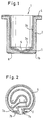
- Fig. 1 shows a sectional view of the in Inhalation device used according to the invention Container 1.
- the container 1 has a cylindrical Side wall 2 with constant wall thickness and is on one Ended with a circular bottom 3.
- the Inside 3a of the bottom 3 is designed so that it ' tapers towards the central region 5 of the base 3. Consequently the thickness of the bottom 3 decreases towards the center.
- the liquid in the container flows automatically in the middle of the container bottom.
- Such Design is special when using the Container in nebulizers advantageous because here over a Atomizer nozzle perpendicular to the central area 5 is arranged, and which in the in the container immersed liquid, the liquid from the Cup is sucked.
- a Heating element 6 in the form of a thick film resistor arranged on the outer surface 3b of the bottom 3 .
- the thick film resistance is by means of Screen printing process on the polished and flat ground outer bottom surface 3b of the container 1 printed and then burned in.
- the resistance of the Dickschit resistance is typically about 12 Ohm.
- the design of the heating element 6 on the The outer bottom surface 3b of the container 1 is shown in FIG. 2 out.
- the two ends of the heating element are as Connections 7a and 7b to the outer edge of the Outside floor surface 3b led out.
- the heating element 6 extends in a straight line from the connecting element 7a in Towards the central area of the floor surface, up to that in Fig. 2 with A point.
- the heating element 6 kinks here at an angle of 90 ° towards the bottom edge, and extends up to that designated B in FIG. 2 Point.
- the heating element describes from point B to point C. a circular path, counterclockwise along the Edges of the outer floor surface and sweeps to point C an angle of approximately 320 °.
- At point C kinks the heating element at an angle of approximately 45 ° in the direction of central area 5, and then runs from Point D to point E parallel to that from point A to point B. trending straight area of the heating element. From point E on the heating element sweeps circularly Surrounding central region 5, an angle of approximately 270 °. At point F the direction of rotation of the Heating element around (now clockwise) and sweeps up to Point G has an angular range of approximately 300 °. In point G kinks the heating element, so that the range from G to H runs parallel to the area A to B or E to D. In Point H then bends the heating element 90 ° in the direction of second pad 7b to connect to this to kick.
- Such a heating element causes an even distribution of heating power on the liquid in the container. It should also be mentioned that the central region 5 is not covered by the heating element is because this area of the floor area, as mentioned before, has a reduced thickness and is therefore more sensitive than that remaining area of the bottom 3. By leaving out the Middle area 5 will overheat the thin one Avoided floor area.
- the arrangement of the heating element is not based on that arrangement described above limited. Instead, can the heating element also spiral, - meander or wavy be trained. Also a zigzag shape or other shapes are possible.
- the one in the inhalation device according to the invention The container is made of an alumina ceramic produced by injection molding.
- the one used Ceramic has a thermal conductivity, which in the Order of magnitude of the thermal conductivity of stainless steel; According to the invention, the thermal conductivity of the used Ceramics can be larger than 15 W / km. This grants one sufficient heat transfer to the one to be heated Liquid.
- a container diameter of for example 34 mm with a container height of 36.5 mm and a wall thickness of typically 2 mm proves to be suitable.
- the ratio of Container wall thickness to container height between 1:16 and 1:20 lie, and the ratio of container wall thickness to Container diameters are between 1:15 and 1:19.
- the inside of the container i.e. Glaze the inside surface 2a and the inside surface 3a. This avoids that in the container liquids in the wall surface of the container penetrate, or they discolor the wall surfaces. This is when used in therapeutic inhalation devices important because of the existing hygiene requirements thorough cleaning of the container is necessary, and Active substance residues in the container should be avoided.
- FIG Regulation of the heating element can be entered.
- the container 1 on an insulating washer 8 arranged.
- the insulating washer 8 can also on the Be glued to the outer bottom surface of the container.
- the Insulating washer consists, for example, of "steatite” (Soapstone) or another suitable ceramic. A Alumina ceramic can also be used.
- the Insulating washer 8 has essentially the same diameter like the bottom 3 of the container, but has a side flattened area.
- the container is regarding the Insulating washer 8 arranged such that the contact surfaces 7a and 7b of the heating element 6 over the flattened area protrude the insulating washer 8.
- connection lines 9a and 9b via which the heating element with Power is supplied, past the insulating washer 8 and can directly with contact surfaces 7a and 7b in Get in touch.
- the other ends of the connecting line 9a and 9b are with an energy source (not shown) connected, which is preferably a 24V AC protective low voltage provides.
- an energy source (not shown) connected, which is preferably a 24V AC protective low voltage provides.
- Temperature sensors 10a and 10b serving NTC resistors introduced so that they with the container bottom 3 in Contact to immediately see the temperature of the To be able to measure the bottom of the container.
- Temperature limiter 11 comprising feed lines 11a and 11b, integrated into the insulation layer.
- the temperature limiter 11 causes the power supply through the Connecting lines 9a and 9b are automatically switched off, if the temperature sensors (NTC resistors) 10a and 10b record a maximum limit. If that's from the NTC resistors sensed temperature below a minimum Limit value drops, the temperature limiter 11 switches on Power supply to the heating element 6 automatically.
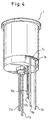
- the Arrangement of temperature limiter 11, temperature sensor 10a and 10b and power lines 9a and 9b go from FIGS. 4 and 5 out.
Landscapes
- Health & Medical Sciences (AREA)
- General Health & Medical Sciences (AREA)
- Veterinary Medicine (AREA)
- Biomedical Technology (AREA)
- Heart & Thoracic Surgery (AREA)
- Hematology (AREA)
- Life Sciences & Earth Sciences (AREA)
- Anesthesiology (AREA)
- Animal Behavior & Ethology (AREA)
- Public Health (AREA)
- Engineering & Computer Science (AREA)
- Thermotherapy And Cooling Therapy Devices (AREA)
- Resistance Heating (AREA)
- Weting (AREA)
- Surface Heating Bodies (AREA)
- Investigating Or Analyzing Materials By The Use Of Fluid Adsorption Or Reactions (AREA)
- Medical Preparation Storing Or Oral Administration Devices (AREA)
Abstract
Description
Die vorliegende Erfindung betrifft eine Inhalationsvorrichtung mit einem Behälter zur Aufnahme einer Flüssigkeit und einem elektrischen Heizelement, das in wärmeleitendem Kontakt mit dem Behälter steht, zum Erwärmen einer in dem Behälter aufgenommenen Flüssigkeit.The present invention relates to a Inhalation device with a container for receiving a liquid and an electric heating element that is in heat-conducting contact with the container for Heating a liquid received in the container.
Zur Behandlung von Atemwegserkrankungen werden verschiedene Inhalationsapparate, wie beispielsweise Vernebler, Zerstäuber und Inhalatoren verwendet. Mittels derartiger Apparate werden therapeutische Wirkstoffe in fein verteilter Form von einem Patienten eingeatmet. In der Regel ist eine Erwärmung der meist in flüssiger bzw. gelöster Form vorliegenden Wirkstoffe vorteilhaft.Various treatments are used to treat respiratory diseases Inhalers, such as nebulizers, Atomizers and inhalers used. By means of such Apparatuses are fine therapeutic agents distributed form inhaled by a patient. In the The rule is heating that is usually in liquid or active ingredients in dissolved form.
Aus DE 30 43 537 ist ein Zerstäuber bekannt, der für die
Verneblung von flüssigen oder festen Stoffen für
Inhalationszwecke vorgesehen ist. Der bekannte Zerstäuber
weist einen Behälter und ein separates elektrisches
Heizelement auf, das in wärmeleitendem Kontakt mit dem
Behälter steht. Als Heizelement dient hierbei ein PCT-Thermistor,
der in einem Körper hoher Wärmeleitfähigkeit
angeordnet ist. Dieser Körper ist typischerweise ein
Metallblock, und umgibt teilweise den Behälter. Dadurch
wird eine gute thermische Kopplung zwischen Heizelement und
Behälter gewährleistet, und das Heizen des Behälters
erfolgt direkt über eine Erwärmung des Metallblocks.From
Ein damit ausgestatteter Vernebler weist allerdings große Abmessungen auf, da der für den Wärmeübertrag von Heizelement auf Behälter notwendige Metallblock viel Platz beansprucht. Das gesamte Gerät ist somit globig und unhandlich, und kann nur als Tischgerät verwendet werden.However, a nebulizer equipped with it has large ones Dimensions due to the heat transfer from Heating element on container necessary metal block a lot of space claimed. The entire device is therefore globular and unwieldy, and can only be used as a tabletop device.
Ein weiterer Nachteil ist die hohe Heizleistung, die benötigt wird um die Temperatur des Metallblocks, und somit die Temperatur der sich in dem Behälter befindende Flüssigkeit, über den PCT-Thermistor zu steuern. Die Temperatursteuerung bzw. -regelung ist außerdem äußerst träge, da der gesamte Metallblock erwärmt werden muß bzw. die Abkühlung des Metallblocks sehr langsam erfolgt.Another disadvantage is the high heating power is needed around the temperature of the metal block, and thus the temperature of the one in the container Liquid to control via the PCT thermistor. The Temperature control is also extreme sluggish because the entire metal block has to be heated or the cooling of the metal block is very slow.
Der vorliegenden Erfindung liegt daher das Problem zugrunde, eine Inhalationsvorrichtung bereitzustellen, die wesentlich kleinere Abmessungen als bisher bekannte Vorrichtungen aufweist, und somit besonders anwenderfreundlich ist.The present invention therefore has the problem to provide an inhalation device that much smaller dimensions than previously known Has devices, and thus particularly is user-friendly.
Dieses Problem wird erfindungsgemäß durch die im Patentanspruch 1 beschriebene Vorrichtung gelöst. Vorteilhafte Ausgestaltungen ergeben sich aus den Unteransprüchen.This problem is inventively by Claim 1 device solved. Advantageous configurations result from the Dependent claims.
Ein zentraler Gedanke der Erfindung besteht hierbei darin, daß der Behälter aus einer Keramik mit einer Wärmeleitfähigkeit λ > 15 W/Km besteht, und daß das Heizelement in Form eines Dickschichtwiderstands unmittelbar auf der Außenseite des Behälterbodens angeordet ist.A central idea of the invention is that the container made of a ceramic with a There is thermal conductivity λ> 15 W / km, and that Heating element in the form of a thick film resistor arranged directly on the outside of the container bottom is.
Durch eine derartige Ausgestallung erübrigt sich ein großer kolbiger Metallblock, und die Abmessungen der erfindungsgemäßen Inhalationsvorrichtung reduziert sich erheblich. Dies hat zur Folge, das die erfindungsgemäße Vorrichtung kein Tischgerät mehr sein muß sondern während des Inhalationsvorgangs von dem Patienten gehalten werden kann. Dies stellt eine konfortablere Anwendung für den Patienten dar, da er sich beim Inhaliervorgang nicht in gerümmter Haltung über ein Tischgerät beugen muß. Statt dessen kann er eine bequeme Sitzhaltung einnehmen, und das Inhalationsgerät in einer für ihn günstigen Stellung halten.Such a configuration makes a large one unnecessary piston metal block, and the dimensions of the Inhalation device according to the invention is reduced considerably. This has the consequence that the invention Device no longer has to be a tabletop device but during of the inhalation process are held by the patient can. This represents a more comfortable application for the Patient because he is not in the inhalation process bent posture must bend over a table device. Instead of of which he can take a comfortable sitting posture, and that Inhaler in a convenient position for him hold.
Im folgenden wird die Erfindung anhand eines Ausführungsbeispiels unter Bezugnahme auf die begleitenden Abbildungen genauer beschrieben. Darin zeigt
- Fig. 1
- eine Schnittansicht des in der erfindungsgemäßen Inhalationsvorrichtung verwendeten Behälters;
- Fig. 2
- eine Bodenansicht des in Fig. 1 gezeigten Behälters, die die Anordnung des Heizelements auf der Aussenbodenfläche des Behälters zeigt;
- Fig. 3
- eine Schnittansicht des in Fig. 1 gezeigten Behälters, zusammen mit einem Isolierkörper und Anschlüssen zur Regelung des Heizelements;
- Fig. 4
- eine perspektivische Darstellung der in Fig. 3 gezeigten Anordnung;
- Fig. 5
- eine weitere perspektivische Darstellung der in Fig. 3 gezeigten Anordnung.
- Fig. 1
- a sectional view of the container used in the inhalation device according to the invention;
- Fig. 2
- a bottom view of the container shown in Figure 1, showing the arrangement of the heating element on the outer bottom surface of the container.
- Fig. 3
- a sectional view of the container shown in Figure 1, together with an insulating body and connections for controlling the heating element.
- Fig. 4
- a perspective view of the arrangement shown in Fig. 3;
- Fig. 5
- a further perspective view of the arrangement shown in Fig. 3.
Fig. 1 zeigt eine Schnittansicht des in der
erfindungsgemäßen Inhalationsvorrichtung verwendeten
Behälters 1. Der Behälter 1 hat eine zylindrische
Seitenwand 2 mit konstanter Wandstärke und ist an einem
Ende mit einem kreisförmigen Boden 3 abgeschlossen. Die
Innenseite 3a des Bodens 3 ist so ausgebildet, daß sie'
konisch auf den Mittelbereich 5 des Bodens 3 zuläuft. Somit
nimmt die Dicke des Bodens 3 zur Mitte hin ab. Durch die in
Richtung Mittelbereich 5 zulaufende innere Bodenfläche 3a
fließt die sich in dem Behälter befindende Flüssigkeit
selbsttätig in die Mitte des Behälterbodens. Eine derartige
Ausgestaltung ist speziell bei einer Verwendung des
Behälters in Verneblern vorteilhaft, da hier über eine
Zerstäuberdüse, die senkrecht zum Mittelbereich 5
angeordnet ist, und die in die sich in dem Behälter
befindenden Flüssigkeit eintaucht, die Flüssigkeit aus dem
Becher angesaugt wird.Fig. 1 shows a sectional view of the in
Inhalation device used according to the invention
Container 1. The container 1 has a cylindrical
Side wall 2 with constant wall thickness and is on one
Ended with a circular bottom 3. The
Inside 3a of the bottom 3 is designed so that it '
tapers towards the
Auf der äußeren Oberfläche 3b des Bodens 3 ist ein
Heizelement 6 in Form eines Dickschichtwiderstands
angeordnet. Der Dickschichtwiderstand wird mittels
Siebdruckverfahren auf die polierte und plan geschliffene
äußere Bodenfläche 3b des Behälters 1 aufgedruckt und
anschließend eingebrannt. Der Widerstand des
Dickschitwiderstands beträgt hierbei typischerweise ca. 12
Ohm. Durch eine derartige Anordnung des Heizelements wird
ein optimaler thermischer Kontakt zwischen Heizelement und
der sich in dem Behälter befindenden Flüssigkeit erreicht,
da sich das Heizelement unmittelbar an dem Behälterbodens,
bzw. sich so nahe wie möglich an der zu erwärmenden
Flüssigkeit befindet, ohne in direkten Kontakt mit der
Flüssigkeit zu treten. Da der Boden 3 des Behälters 1 sehr
dünn ausgebildet werden kann, findet überdies ein rascher
Übergang der Wärme statt. On the
Die Ausgestalltung des Heizelements 6 auf der
Aussenbodenfläche 3b des Behälters 1 geht aus Fig. 2
hervor. Die beiden Enden des Heizelements sind als
Anschlüsse 7a und 7b an den äußeren Rand der
Aussenbodenfläche 3b herausgeführt. Das Heizelement 6
erstreckt sich hierbei geradlinig vom Anschlußelement 7a in
Richtung Mittelbereich der Bodenfläche, bishin zu dem in
Fig. 2 mit A bezeichneten Punkt. Das Heizelement 6 knickt
hier in einem Winkel von 90° in Richtung des Bodenrands ab,
und erstreckt sich bis zu dem in Fig. 2 mit B bezeichneten
Punkt. Von Punkt B bis Punkt C beschreibt das Heizelement
eine kreisförmige Bahn, entgegen Uhrzeigersinn entlang des
Rands der Aussenbodenfläche verlaufend, und überstreicht
bishin zu Punkt C einen Winkel von ungefähr 320°. An Punkt
C knickt das Heizelement unter einem Winkel von ungefähr
45° in Richtung Mittelbereich 5 ab, und verläuft dann von
Punkt D bis Punkt E parallel zu dem von Punkt A bis Punkt B
verlaufenden geraden Bereich des Heizelements. Von Punkt E
an überstreicht das Heizelement kreisförmig, den
Mittelbereich 5 umgebend, einen Winkel von ungefähr 270°.
In Punkt F dreht sich der Drehsinn des Verlaufs des
Heizelements um (nun im Uhrzeigersinn) und überstreicht bis
Punkt G einen Winkelbereich von ungefähr 300°. In Punkt G
knickt das Heizelement ab, so daß der Bereich von G bis H
parallel zu dem Bereich A bis B bzw. E bis D verläuft. In
Punkt H knickt das Heizelement dann um 90° in Richtung der
zweiten Anschlußfläche 7b ab, um mit dieser in Verbindung
zu treten. Ein derart ausgebildetes Heizelement bewirkt
eine gleichmäßige Verteilung der Heizleistung auf die sich
in dem Behälter befindenden Flüssigkeit. Zudem sei erwähnt,
daß der Mittelbereich 5 nicht von dem Heizelement bedeckt
ist, da dieser Bereich der Bodenfläche, wie zuvor erwähnt,
eine reduzierte Dicke hat und somit empfindlicher als der
verbleibende Bereich des Bodens 3 ist. Durch Aussparen des
Mittelbereichs 5 wird ein Überheizen des dünnen
Bodenbereichs vermieden.The design of the
Die Anordnung des Heizelements ist jedoch nicht auf die oben beschriebene Anordung beschränkt. Statt dessen kann das Heizelemet auch spiral, - meander oder wellenförmig ausgebildet sein. Auch eine Zickzackform oder andere Formen sind möglich.However, the arrangement of the heating element is not based on that arrangement described above limited. Instead, can the heating element also spiral, - meander or wavy be trained. Also a zigzag shape or other shapes are possible.
Der in der erfindungsgemäßen Inhalationsvorrichtung verwendet Behälter wird aus einer Aluminiumoxid-Keramik mittels Spritzgußverfahren hergestellt. Die verwendete Keramik hat eine Wärmeleitfähigkeit, die in der Größenordnung der Wärmeleitfähigkeit von Edelstahl liegt; erfindungsgemäß muß die Wärmeleitfähigkeit der verwendeten Keramik größer als 15 W/Km sein. Dies gewährt einen ausreichenden Wärmeübertrag an die zu erwärmende Flüssigkeit.The one in the inhalation device according to the invention The container is made of an alumina ceramic produced by injection molding. The one used Ceramic has a thermal conductivity, which in the Order of magnitude of the thermal conductivity of stainless steel; According to the invention, the thermal conductivity of the used Ceramics can be larger than 15 W / km. This grants one sufficient heat transfer to the one to be heated Liquid.
Bei der Herstellung des Keramikbehälters muß zudem eine Rißbildung vermieden werden, was durch die Gestaltung der Abmessungen erreicht wird. Ein Behälterdurchmesser von beispielsweise 34 mm bei einer Behälterhöhe von 36,5 mm und einer Wanddicke von typischerweise 2 mm erweist sich als geeignet. In der Regel sollte das Verhältnis von Behälterwanddicke zu Behälterhöhe zwischen 1:16 und 1:20 liegen, und das Verhältnis von Behälterwanddicke zu Behälterdurchmesser zwischen 1:15 und 1:19 liegen.In the manufacture of the ceramic container, a Cracking can be avoided, which is due to the design of the Dimensions is reached. A container diameter of for example 34 mm with a container height of 36.5 mm and a wall thickness of typically 2 mm proves to be suitable. As a rule, the ratio of Container wall thickness to container height between 1:16 and 1:20 lie, and the ratio of container wall thickness to Container diameters are between 1:15 and 1:19.
Zudem ist es vorteilhaft das Innere des Behälters, d.h. Innenseitenfläche 2a und Innenbodenfläche 3a, zu glasieren. Dadurch wird vermieden, daß die sich in dem Behälter befindenden Flüssigkeiten in die Wandfläche des Behälters eindringen, bzw. diese die Wandflächen verfärben. Dies ist bei der Verwendung in therapeutischen Inhalationsgeräten wichtig, da aufgrund der bestehenden Hygieneanforderungen eine gründliche Reinigung des Behälters notwendig ist, und Wirstoffrückstände in dem Behälter zu vermeiden sind.In addition, it is advantageous to use the inside of the container, i.e. Glaze the inside surface 2a and the inside surface 3a. This avoids that in the container liquids in the wall surface of the container penetrate, or they discolor the wall surfaces. This is when used in therapeutic inhalation devices important because of the existing hygiene requirements thorough cleaning of the container is necessary, and Active substance residues in the container should be avoided.
Im folgenden soll unter Bezugnahme auf Fig. 3 auf die
Regelung des Heizelements eingegangen werden. Wie aus Fig.
3 ersichtlich, wird der Behälter 1 auf einer Isolierscheibe
8 angeordet. Die Isolierscheibe 8 kann auch auf der
Aussenbodenfläche des Behälters aufgeklebt sein. Die
Isolierscheibe besteht beispielsweise aus "Steatit"
(Speckstein) oder einer anderen geeigneten Keramik. Eine
Aluminiumoxid-Keramik kann ebenso verwendet werden. Die
Isolierscheibe 8 hat im wesentlichen denselben Durchmesser
wie der Boden 3 des Behälters, weist jedoch seitlich einen
abgeflachten Bereich auf. Der Behälter ist bezüglich der
Isolierscheibe 8 derart angeordnet, daß die Kontaktflächen
7a und 7b des Heizelements 6 über den abgeflachten Bereich
der Isolierscheibe 8 überstehen. Somit werden die
Anschlußleitungen 9a und 9b, über die das Heizelement mit
Strom versorgt wird, an der Isolierscheibe 8 vorbeigeführt
und können unmittelbar mit Kontaktflächen 7a und 7b in
Kontakt treten. Die anderen Enden der Anschlußleitung 9a
und 9b sind mit einer Energiequelle (nicht dargestellt)
verbunden, die vorzugsweise eine 24V AC-Schutzkleinspannung
bereitstellt. Durch die Verwendung eines Transformators
wird hierbei die Netzspannung von 220V
heruntertransformiert. Eine derartige Ausgestaltung ist
insbesondere im Hinblick auf die Sicherheit des Patienten
von Vorteil, da dieser die erfindungsgemäße
Inhalationsvorrichtung während des Inhalationsvorgans in
den Händen hält.In the following, reference is made to FIG
Regulation of the heating element can be entered. As from Fig.
3 can be seen, the container 1 on an insulating
Ferner sind in die Isolierscheibe 8 die als
Temperaturmeßfühler 10a und 10b dienenden NTC-Widerstände
derart eingeführt, daß sie mit dem Behälterboden 3 in
Kontakt treten, um unmittelbar die Temperatur des
Behälterbodens messen zu können. Zudem ist ein
Temperaturbegrenzer 11, umfassend Zuleitungen 11a und 11b,
in die Isolierschicht integriert. Der Temperaturbegrenzer
11 bewirkt, daß die Stromversorgung über die
Anschlußleitungen 9a und 9b automatisch abgeschaltet wird,
wenn die Temperaturfühler (NTC-Widerstände) 10a und 10b
einen maximalen Grenzwert erfassen. Wenn die von den NTC-Widerständen
erfaßte Temperatur unter einen minimalen
Grenzwert sinkt, schaltet der Temperaturbegrenzer 11 die
Stromzufuhr an das Heizelement 6 automatisch ein. Die
Anordnung von Temperaturbegrenzer 11, Teperaturfühler 10a
und 10b und Stromleitungen 9a und 9b gehen aus Fig. 4 und 5
hervor.Furthermore, in the insulating
Claims (16)
- Inhaler with a container (1) for holding a liquid and an electric heating element (6) which is in heat-conducting contact with the container (1), for heating the liquid held in the container (1), characterised in that the container (1) is made of a ceramic whose thermal conductivity λ > 15 W/km, and the heating element (6) is a thick-film resistor which is arranged on the outer surface of the container (1).
- Inhaler according to claim 1, characterised in that the container (1) is made of an aluminium oxide ceramic.
- Inhaler according to claims 1 and 2, characterised in that the inner surfaces of the container (2a, 3a) are glazed.
- Inhaler according to any of the preceding claims, characterised in that the container (1) comprises an inner bottom surface (3a) inclined towards the centre.
- Inhaler according to any of the preceding claims, characterised in that the outer bottom surface (3b) of the container is surface-ground.
- Inhaler according to any of the preceding claims, characterised in that the container wall thickness is in a ratio of 1:16 to 1:20 to the container height.
- Inhaler according to any of the preceding claims, characterised in that the container wall thickness is in a ratio of 1:15 to 1:19 to the container diameter.
- Inhaler according to any of the preceding claims, characterised in that the thick-film resistor is arranged only on an outer bottom surface (3b) of the container.
- Inhaler according to any of the preceding claims, characterised in that the thick-film resistor is circular, spiral, meander-shaped or undulating or has a zigzag shape.
- Inhaler according to any of the preceding claims, characterised in that the centre region (5) of the bottom surface of the container is not covered by the thick-film resistor.
- Inhaler according to any of the preceding claims, characterised in that the thick-film resistor has a resistance of approx. 12 Ω.
- Inhaler according to any of the preceding claims, characterised in that an insulating body is provided, which is glued to the outer bottom surface of the container and in which are arranged a plurality of temperature sensors (10, 11).
- Inhaler according to claim 12, characterised in that the temperature sensors arranged in the insulating body are NTC resistors (10).
- Inhaler according to claim 12, characterised in that a temperature limiter (11) is provided.
- Inhaler according to claim 12, characterised in that the insulating body (8) is made of ceramic or steatite.
- Inhaler according to any of the preceding claims, characterised in that the heating element (6) is connected by the connecting wires (9a, 9b) to a 24 V protective low a.c. voltage.
Applications Claiming Priority (2)
| Application Number | Priority Date | Filing Date | Title |
|---|---|---|---|
| DE19742206 | 1997-09-24 | ||
| DE19742206A DE19742206A1 (en) | 1997-09-24 | 1997-09-24 | Inhalation device |
Publications (3)
| Publication Number | Publication Date |
|---|---|
| EP0904791A2 EP0904791A2 (en) | 1999-03-31 |
| EP0904791A3 EP0904791A3 (en) | 2000-01-12 |
| EP0904791B1 true EP0904791B1 (en) | 2003-12-03 |
Family
ID=7843511
Family Applications (1)
| Application Number | Title | Priority Date | Filing Date |
|---|---|---|---|
| EP98118086A Expired - Lifetime EP0904791B1 (en) | 1997-09-24 | 1998-09-24 | Inhalation device |
Country Status (3)
| Country | Link |
|---|---|
| EP (1) | EP0904791B1 (en) |
| AT (1) | ATE255440T1 (en) |
| DE (2) | DE19742206A1 (en) |
Families Citing this family (2)
| Publication number | Priority date | Publication date | Assignee | Title |
|---|---|---|---|---|
| GB0103658D0 (en) | 2001-02-14 | 2001-03-28 | Strix Ltd | Electric beverage maker |
| GB0126150D0 (en) * | 2001-10-31 | 2002-01-02 | Gw Pharma Ltd | A device method and resistive element for vaporising a substance |
Family Cites Families (6)
| Publication number | Priority date | Publication date | Assignee | Title |
|---|---|---|---|---|
| DE3043537A1 (en) | 1980-11-18 | 1982-07-08 | Brugger, Inge, 8130 Starnberg | Atomiser with pre-heating facility - has PTC thermistor as combination heating element and thermostat |
| US4819625A (en) * | 1987-11-12 | 1989-04-11 | Cimco, Inc. | Nebulizer heater |
| JPH01194282A (en) * | 1988-01-28 | 1989-08-04 | Ngk Insulators Ltd | Ceramics heater, electrochemical element, and oxygen analysis device |
| JPH01117355U (en) * | 1988-01-28 | 1989-08-08 | ||
| US5408574A (en) * | 1989-12-01 | 1995-04-18 | Philip Morris Incorporated | Flat ceramic heater having discrete heating zones |
| US5093894A (en) * | 1989-12-01 | 1992-03-03 | Philip Morris Incorporated | Electrically-powered linear heating element |
-
1997
- 1997-09-24 DE DE19742206A patent/DE19742206A1/en not_active Withdrawn
-
1998
- 1998-09-24 DE DE59810319T patent/DE59810319D1/en not_active Expired - Lifetime
- 1998-09-24 EP EP98118086A patent/EP0904791B1/en not_active Expired - Lifetime
- 1998-09-24 AT AT98118086T patent/ATE255440T1/en not_active IP Right Cessation
Also Published As
| Publication number | Publication date |
|---|---|
| ATE255440T1 (en) | 2003-12-15 |
| EP0904791A3 (en) | 2000-01-12 |
| EP0904791A2 (en) | 1999-03-31 |
| DE19742206A1 (en) | 1999-04-22 |
| DE59810319D1 (en) | 2004-01-15 |
Similar Documents
| Publication | Publication Date | Title |
|---|---|---|
| DE602004004528T2 (en) | DEVICE FOR HEATING A LIQUID FOR A HOME APPARATUS, HOUSEHOLD EQUIPMENT EQUIPPED WITH THE EQUIPMENT | |
| EP0397043B1 (en) | Apparatus for generating cold and heat | |
| DE3012150C2 (en) | Endoscope device with a medical instrument arrangement | |
| US6253104B1 (en) | Method of preparing pharmaceutical Moxa extract and apparatus for electrical moxibustion using the same extract | |
| EP0564953B1 (en) | Heating device for insufflation apparatus | |
| DE1952251A1 (en) | Temperature measuring device | |
| DE2943477C2 (en) | Control switch for hotplate or heat storage device - has rotary setting member also operating switch that connects in extra heating element | |
| DE3311811A1 (en) | Device for treating the airways with hot air | |
| DE10021512A1 (en) | Electric heating unit, especially for liquid media | |
| EP4588377A1 (en) | Heating assembly and aerosol generation device | |
| DE2411663A1 (en) | ELECTRIC HEATING PLATE | |
| EP0904791B1 (en) | Inhalation device | |
| DE69704889T2 (en) | Electrical resistance element for floor heating, especially for kettles | |
| DE3027932A1 (en) | LIQUID LEVEL SENSOR. | |
| DE60131255T2 (en) | TEMPERATURE SENSOR | |
| WO1994028959A9 (en) | INHALER | |
| DE3941168A1 (en) | Heated micro-titration plate - has cuvettes, plate-shaped member, temp. probes and sensors, ceramic plate and heating elements | |
| DE3043537C2 (en) | ||
| DE3708945A1 (en) | INHALING DEVICE | |
| DE4331559A1 (en) | Continuous-flow electric resistance heater for gases or liqs. | |
| EP0441193B1 (en) | Measuring instrument for determining the tendency towards sweating of people | |
| DE2109470C3 (en) | Electric soldering iron | |
| DE2659454C3 (en) | Device for heat treatment | |
| DE69918453T2 (en) | MEDICAL THERMOMETER | |
| DE4031081C2 (en) | Sensor unit for a device for boiling liquid |
Legal Events
| Date | Code | Title | Description |
|---|---|---|---|
| PUAI | Public reference made under article 153(3) epc to a published international application that has entered the european phase |
Free format text: ORIGINAL CODE: 0009012 |
|
| AK | Designated contracting states |
Kind code of ref document: A2 Designated state(s): AT CH DE LI |
|
| AX | Request for extension of the european patent |
Free format text: AL;LT;LV;MK;RO;SI |
|
| PUAL | Search report despatched |
Free format text: ORIGINAL CODE: 0009013 |
|
| AK | Designated contracting states |
Kind code of ref document: A3 Designated state(s): AT BE CH CY DE DK ES FI FR GB GR IE IT LI LU MC NL PT SE |
|
| AX | Request for extension of the european patent |
Free format text: AL;LT;LV;MK;RO;SI |
|
| 17P | Request for examination filed |
Effective date: 20000308 |
|
| AKX | Designation fees paid |
Free format text: AT CH DE LI |
|
| GRAH | Despatch of communication of intention to grant a patent |
Free format text: ORIGINAL CODE: EPIDOS IGRA |
|
| GRAS | Grant fee paid |
Free format text: ORIGINAL CODE: EPIDOSNIGR3 |
|
| GRAA | (expected) grant |
Free format text: ORIGINAL CODE: 0009210 |
|
| AK | Designated contracting states |
Kind code of ref document: B1 Designated state(s): AT CH DE LI |
|
| REG | Reference to a national code |
Ref country code: CH Ref legal event code: EP |
|
| REF | Corresponds to: |
Ref document number: 59810319 Country of ref document: DE Date of ref document: 20040115 Kind code of ref document: P |
|
| PG25 | Lapsed in a contracting state [announced via postgrant information from national office to epo] |
Ref country code: AT Free format text: LAPSE BECAUSE OF NON-PAYMENT OF DUE FEES Effective date: 20040924 |
|
| PG25 | Lapsed in a contracting state [announced via postgrant information from national office to epo] |
Ref country code: LI Free format text: LAPSE BECAUSE OF NON-PAYMENT OF DUE FEES Effective date: 20040930 Ref country code: CH Free format text: LAPSE BECAUSE OF NON-PAYMENT OF DUE FEES Effective date: 20040930 |
|
| PLBE | No opposition filed within time limit |
Free format text: ORIGINAL CODE: 0009261 |
|
| STAA | Information on the status of an ep patent application or granted ep patent |
Free format text: STATUS: NO OPPOSITION FILED WITHIN TIME LIMIT |
|
| 26N | No opposition filed |
Effective date: 20040906 |
|
| REG | Reference to a national code |
Ref country code: CH Ref legal event code: PL |
|
| PGFP | Annual fee paid to national office [announced via postgrant information from national office to epo] |
Ref country code: DE Payment date: 20130924 Year of fee payment: 16 |
|
| REG | Reference to a national code |
Ref country code: DE Ref legal event code: R119 Ref document number: 59810319 Country of ref document: DE |
|
| REG | Reference to a national code |
Ref country code: DE Ref legal event code: R119 Ref document number: 59810319 Country of ref document: DE Effective date: 20150401 |
|
| PG25 | Lapsed in a contracting state [announced via postgrant information from national office to epo] |
Ref country code: DE Free format text: LAPSE BECAUSE OF NON-PAYMENT OF DUE FEES Effective date: 20150401 |