EP0904532B2 - Procede pour l'evaluation des effets de defauts du fil sur des configurations textiles en surface - Google Patents
Procede pour l'evaluation des effets de defauts du fil sur des configurations textiles en surface Download PDFInfo
- Publication number
- EP0904532B2 EP0904532B2 EP97922799A EP97922799A EP0904532B2 EP 0904532 B2 EP0904532 B2 EP 0904532B2 EP 97922799 A EP97922799 A EP 97922799A EP 97922799 A EP97922799 A EP 97922799A EP 0904532 B2 EP0904532 B2 EP 0904532B2
- Authority
- EP
- European Patent Office
- Prior art keywords
- yarn
- values
- image
- fabric
- parameters
- Prior art date
- Legal status (The legal status is an assumption and is not a legal conclusion. Google has not performed a legal analysis and makes no representation as to the accuracy of the status listed.)
- Expired - Lifetime
Links
- 238000000034 method Methods 0.000 title claims description 19
- 239000004753 textile Substances 0.000 title claims description 8
- 230000007547 defect Effects 0.000 title claims description 6
- 230000000694 effects Effects 0.000 title claims description 5
- 239000004744 fabric Substances 0.000 claims description 44
- 238000004088 simulation Methods 0.000 claims description 25
- 238000010586 diagram Methods 0.000 claims description 8
- 238000004364 calculation method Methods 0.000 claims description 7
- 238000012360 testing method Methods 0.000 claims description 4
- 239000000835 fiber Substances 0.000 description 22
- 238000009826 distribution Methods 0.000 description 4
- 238000011156 evaluation Methods 0.000 description 4
- 239000002994 raw material Substances 0.000 description 4
- 238000005520 cutting process Methods 0.000 description 3
- 238000004519 manufacturing process Methods 0.000 description 3
- 238000005259 measurement Methods 0.000 description 3
- 238000012937 correction Methods 0.000 description 2
- 239000000463 material Substances 0.000 description 2
- 239000000203 mixture Substances 0.000 description 2
- 210000000056 organ Anatomy 0.000 description 2
- 230000009466 transformation Effects 0.000 description 2
- 206010020112 Hirsutism Diseases 0.000 description 1
- 230000006978 adaptation Effects 0.000 description 1
- 230000027455 binding Effects 0.000 description 1
- 238000009739 binding Methods 0.000 description 1
- 230000001186 cumulative effect Effects 0.000 description 1
- 238000003384 imaging method Methods 0.000 description 1
- 230000007774 longterm Effects 0.000 description 1
- 230000000737 periodic effect Effects 0.000 description 1
- 238000012545 processing Methods 0.000 description 1
- 230000003595 spectral effect Effects 0.000 description 1
Images


Classifications
-
- G—PHYSICS
- G01—MEASURING; TESTING
- G01N—INVESTIGATING OR ANALYSING MATERIALS BY DETERMINING THEIR CHEMICAL OR PHYSICAL PROPERTIES
- G01N21/00—Investigating or analysing materials by the use of optical means, i.e. using sub-millimetre waves, infrared, visible or ultraviolet light
- G01N21/84—Systems specially adapted for particular applications
- G01N21/88—Investigating the presence of flaws or contamination
- G01N21/89—Investigating the presence of flaws or contamination in moving material, e.g. running paper or textiles
- G01N21/892—Investigating the presence of flaws or contamination in moving material, e.g. running paper or textiles characterised by the flaw, defect or object feature examined
- G01N21/898—Irregularities in textured or patterned surfaces, e.g. textiles, wood
- G01N21/8983—Irregularities in textured or patterned surfaces, e.g. textiles, wood for testing textile webs, i.e. woven material
-
- G—PHYSICS
- G01—MEASURING; TESTING
- G01N—INVESTIGATING OR ANALYSING MATERIALS BY DETERMINING THEIR CHEMICAL OR PHYSICAL PROPERTIES
- G01N21/00—Investigating or analysing materials by the use of optical means, i.e. using sub-millimetre waves, infrared, visible or ultraviolet light
- G01N21/84—Systems specially adapted for particular applications
- G01N21/88—Investigating the presence of flaws or contamination
- G01N21/89—Investigating the presence of flaws or contamination in moving material, e.g. running paper or textiles
- G01N21/8914—Investigating the presence of flaws or contamination in moving material, e.g. running paper or textiles characterised by the material examined
- G01N21/8915—Investigating the presence of flaws or contamination in moving material, e.g. running paper or textiles characterised by the material examined non-woven textile material
-
- G—PHYSICS
- G01—MEASURING; TESTING
- G01N—INVESTIGATING OR ANALYSING MATERIALS BY DETERMINING THEIR CHEMICAL OR PHYSICAL PROPERTIES
- G01N33/00—Investigating or analysing materials by specific methods not covered by groups G01N1/00 - G01N31/00
- G01N33/36—Textiles
- G01N33/367—Fabric or woven textiles
-
- G—PHYSICS
- G01—MEASURING; TESTING
- G01N—INVESTIGATING OR ANALYSING MATERIALS BY DETERMINING THEIR CHEMICAL OR PHYSICAL PROPERTIES
- G01N33/00—Investigating or analysing materials by specific methods not covered by groups G01N1/00 - G01N31/00
- G01N33/36—Textiles
- G01N33/365—Filiform textiles, e.g. yarns
Definitions
- the invention relates to a method for assessing the effect of yarn defects on fabrics by simulating an image of the fabric from a given yarn.
- a disadvantage of the known method consists in the fact that this simulation does not exactly match the image of a real tissue or knitted fabric, because simplifying assumptions have been made for the simulation, which have an effect in this sense.
- One such assumption is to simulate side-by-side yarn sections in the simulation and to weight or even neglect bonds between warp threads and weft threads. This makes the assessment of a simulated fabric or knitted fabric more difficult. A correct assessment therefore requires some practice.
- the object which is to be solved by the invention is now to remedy the disadvantages mentioned and to provide a method by which the evaluation of simulated textile fabrics can be made with greater certainty.
- the object is achieved by the fact that an image of a woven or knitted fabric, which has been created by a known simulation, taking into account parameters of a really existing and measured yarn, is compared with the image of a reference fabric or reference knit, for the parameter of one according to statistical conditions classified reference yarn can be used.
- the reference yarn is characterized by parameters corresponding, for example, to average values as can be seen from published statistics.
- the parameters of the reference yarn can be obtained by measuring a really existing reference yarn or by calculation from given statistical values.
- an image of a reference tissue is to be created which is more similar to the image of the tissue of given yarn and with which the image of the known simulated tissue can be compared.
- the image of the reference tissue can be achieved by imaging a so-called Garnschautafel, which is constructed with a reference yarn.
- the image of the reference yarn can be generated by simulating a fabric from a reference yarn. The simulation of the reference yarn was done by calculating parameters of the yarn. The best result is obtained by simulating two fabrics in the same way, with the only difference being in the values for the parameters, one being from a given yarn and the other from a reference yarn.
- the advantages achieved by the invention are in particular that the reference fabric or knitted fabric is displayed in exactly the same way as the simulated fabric or knitted fabric on a screen or on paper, so that deviations between the images directly to deviations between real knitted fabrics and fabrics and are considered as a consequence of different values for the selected parameters.
- the viewer who has to judge them, can now also apply his own subjective criteria with which he wants to judge them. He does not have to fear any distortion of his criteria, as they would have to be taken into account if the images are not directly comparable.
- the method according to the invention consists of the known simulation of an image of a textile fabric which is to be constructed from a given yarn whose parameters are measured and on the other hand from the simulation of an image of a textile fabric constructed from a reference yarn.
- a reference yarn Here it is possible to calculate parameters of a reference yarn. This possibility will be described in more detail below with reference to the figures. With the individual figures and the necessary process steps are to be explained.
- Fig. 1 shows an image 52 of a fabric constructed according to the present invention by simulation from a reference yarn.
- the reference yarn is given by calculated parameters.
- This image is intended to serve as a reference for images of fabrics constructed from other yarns by simulation, where the yarns are simulated based on measurements on a real yarn.
- Such an image 51 is also shown for comparison.
- a comparison of the two images allows to detect deviations in the images 51, 52 and further evaluate. For example, a moiré effect can be seen in FIG. 51, the possible causes of which are known per se and can be attributed, for example, to periodic errors in the yarn.
- FIG. 2 shows a so-called stack diagram 1 in which a curve 2 for a frequency distribution and a curve 3 as a cumulative curve of the frequency distribution can be seen.
- the stack diagram is the starting point for the calculation of the yarn parameters.
- Curves 2 and 3 are plotted along a horizontal axis 4 along which marks or values for lengths of textile fibers are plotted.
- a vertical axis 5 there are marks or values for the percentage of fibers of definite length. From the curve 2 it is thus easy to deduce that the largest proportion of the fibers of a stack from which the values originate have the length corresponding to a value at the point 6. From curve 3 it can be seen that 100% of the fibers are at least infinitely short, but that there are no infinitely long fibers.
- stack diagrams are either to be found in the specialist literature or can be measured with commercially available devices for raw materials. Such devices are sold by the company Zellweger Uster under the name AFIS or AL100.
- the stack diagram is one of the bases of yarn parameter calculation. It provides values which are characteristic of a raw material, here in particular a reference raw material from which one starts, that is. it indicates to what extent the reference yarn can be assumed to have an ideal distribution of the fiber lengths. Depending on its composition, the yarn made from this raw material exhibits more or less pronounced quasi-periodic irregularities which can be represented in spectrograms.
- FIG. 3 shows in horizontal and vertical representation shifted four spectrogram curves 7, 8, 9, 10 for each yarn consisting of fibers of constant length, the length of the fibers for these yarns from the spectrogram 7 to the spectrogram curve 10 increases. Lengths of fibers for these yarns can be seen in Fig. 2 on the axis 4, for example, at points 6, 11, 12, and 13. Along axes 14 are values for wavelengths and along an axis 15 values for amplitudes or the power density (as detected by regularity checker) are plotted.
- p f 1 n ⁇ sin 2 ⁇ fL v in which p is the power density as measured in a known yarn uniformity tester; n is the number of fibers in the cross-section of the yarn, L is the length of the fibers f the measuring frequency and v mean the measuring speed of the yarn.
- power is measured with band filters that have constant relative bandwidth. For example, 5 band filters are arranged per octave whose band boundaries touch each other. Thus, instead of the continuous curve shown here, a staircase-shaped spectrogram curve results.
- known yarn testers provide representations of spectrograms in which, instead of the power density, the root of the power or instead of the frequency, the wavelength is given on a logarithmic scale. This is taken into account in the illustration of the formula (B) shown.
- a spectrogram curve for a yarn consisting of fibers of different lengths as is usual in real yarns is to be derived.
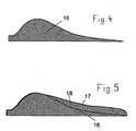
- FIG. 4 therefore shows a spectrogram curve 16 which has been produced by superposition of a plurality of spectrogram curves, such as the spectrogram curves 7, 8, 9, 10. From the stacked diagram (FIG. 1), values for the frequency from the curves 2 or 3 can be taken for fiber length values, which are given for example at constant intervals along the axis 14. These values can be used to weight the spectrograms for the respective fiber lengths.
- FIG. 5 shows a spectrogram curve 17 derived from the spectrogram curve 16.
- the spectrogram curve 17 accounts for errors that a yarn has as a result of production conditions that are not ideal. Such, for example, caused by production machines or not corrected errors are usually long-wavelength, which is why the spectrogram curve 17 deviates from the spectrogram curve 16, in particular in a region 18.
- the deviation in the region 18 can be determined by values from known length variation curves CV (L) and mass variation curves CVm, as will be explained below.
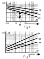
- Fig. 6 shows three boundaries 19, 20 and 21 which delimit fields in which length variation curves CV (L) can be for yarns of different quality. These are plotted on a horizontal axis 22 with values for cut lengths of the yarns and adjacent to a vertical axis 23, with values for percent deviations from an average.
- the limit 19 concerns yarns of the worst, border 21 yarns of the best quality. From this it can be seen that for yarns of good quality the deviations from the average decrease more with increasing cutting length than for yarns of poor quality.
- a length variation curve 50 of an ideal yarn is drawn. Since it is known according to FIGS. 3 and 4 that long-wave defects in the yarn have smaller amplitudes than short-wave defects, FIG.
- the amplitude values from the spectrogram curve 16 must be corrected or multiplied by a factor which takes into account the real long-wavelength errors present in the non-ideal yarn.
- This correction should take place in the sloping branch of the spectrogram curve 16, in particular for cutting lengths over approximately 0.5 m in the region 18.
- the factor is formed for different cutting lengths and results from the distance a between the length variation curve 50 and the selected boundary 21, 20, 19. Since the values are logarithmically plotted along both axes 22, 23, this distance a can be determined by de-logarithmization directly into a Factor to be converted.
- the spectrogram curve 17 arises from the spectrogram curve 16.
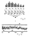
- a yarn signal is now to be produced by calculation, as could be output by a yarn tester.
- This is shown in FIG. 8.
- an inverse Fourier transform is used, which is to lead from signals in the spectral range to an output signal representing cross-sectional or mass deviations along the yarn.
- the spectrogram curve 17 is logarithmically divided into classes, which are represented here by rectangles 29 to 35. On a logarithmic scale, these classes have equal lengths among themselves. Each class 29 to 35 thus also represents a wavelength range which can be further subdivided into several channels, e.g. in 5 to 10 channels per octave.
- Each class 29-35 is assigned a sine wave generator 36-42 whose frequency is inversely proportional to the wavelength of the class and whose amplitude is proportional to the height of the class, or to the frequency (corresponding to the height of the rectangle) of the variations represented by the class.
- Each generator 36-42 thus outputs a sinusoidal signal that is mixed together by superimposition to produce a single output representing mass deviations from an average over time, such as shown in FIG. 10.
- a coefficient of variation can be determined in a manner known per se.
- FIG. 7 shows three boundaries 24, 25 and 26 within which values of mass variation may be for yarns of different quality. These are plotted on a horizontal axis 27 with values for the so-called yarn number or fineness (which is inversely proportional to the thickness) and adjacent to an axis 28, with values for coefficients of variation CV in percent of an average.
- the limit 24 concerns yarns of the worst, border 26 yarns of the best quality. From this it can be seen that for yarns of good quality the deviations from the mean increase with increasing yarn count less than for yarns of poor quality. Now you have an idea about the quality of the yarn that you want to simulate.
- the coefficient of variation of one of the boundaries 24, 25, 26 can be taken for the relevant yarn from FIG. 7 for a specific yarn count. If one compares this with the coefficient of variation for the output signal according to FIG. 8, one probably identifies a difference. From this one determines a factor with which the entire output signal is multiplied, with which each deflection of the signal is increased or reduced at a time. This creates a simulated signal that is largely adapted to real circumstances.
- each sine-wave generator (FIG. 8) can be modulated before the mixing with a random signal in the frequency, so that a broadband signal is produced.
- the bandwidth of the random signal preferably corresponds to the channel spacings.
- yarns usually still have so-called rare events such as nits, thick spots, thin spots or foreign bodies, which were not considered until then.
- Such events can be simulated with a random generator and added to the signal.
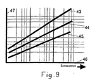
- the frequency and magnitude of such events can be found in the publication "USTER STATISTICS" for the relevant events. Frequency values can be entered into the random number generator, as can be taken from FIG. 9, for example.
- FIG. 9 shows an example of a graphic as found in the above-mentioned USTER STATISTICS in addition to graphics according to FIGS. 6 and 7.
- This shows three boundaries 43, 44 and 45 for values indicating a number of rare events per yarn length. These values and limits are plotted along a horizontal axis 46 with values for the yarn count and adjacent to an axis 47, with values for the number of events per 1000 meters of yarn.
- the limit 43 concerns yarns of the worst, border 45 yarns of the best quality. From this it can be seen that for yarns of good quality, the number of events increases more slowly with increasing yarn count than with yarns of poor quality. Admixture with the random generator can be done with a randomly generated amplitude and length that quantifies the deviation of the event from the mean.
- the random generator then outputs pulses which are superimposed on the output signal according to FIG. 8 and which correspond to an empirical value of typical imperfections.
- FIG. 9 is just one example of many statistics that also separately indicate the frequency of special imperfections such as thick spots, thinning sites, nits, shell parts, foreign matter, and so forth.
- FIG. 10 shows a variation curve 48, which is known per se for yarn, for mass variations, which are shown deviating from an average value M.
- the method illustrated in FIGS. 2 to 8 now provides such a variation curve 48 recorded over an axis 49 on which values for the yarn length are plotted.
- the position in the yarn or along the yarn is also known.
- the variation curve 48 does not differ in its nature from a variation curve determined by measuring a yarn in a yarn inspector.
- the individual variations or signal points or the values they represent can be converted directly into pixels and strung together so that a simulation of a Garns arises.
- the deviations of the signal points indicate a measure of the intensity of a color or a gray value. If now several rows of such pixels are lined up, the result is, for example, the image 51 (FIG. 1) from which clearly individual rows 60, 61, 62 can be seen, which are composed of pixels, here only in two intensities or gradations, ie black or white appear.
- the image 52 is created in the same way, with the only difference that the parameters or the measurement signal, which were converted into pixels come from a yarn that serves as a reference and were determined by measuring the yarn in a Garnprüfer or by simulation. In a similar way, simulations for fabrics with different bindings are possible, for example for knitted fabrics.
- the pixels of a yarn are arranged in the image according to the course of the yarn in the respective fabric. Just as in warp the warp and weft threads intersect and thus overlap, the threads or yarns in the knitted fabric form stitches. In both cases, one may or may not take into account the overlap in the simulation, due to increased intensity at this point.
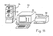
- FIG. 11 shows a yarn testing device 53 known per se, which consists of the actual testing device 54, an evaluation and operating unit 55 and a printer 56.
- the testing device 54 is provided with one or more measuring modules 57, which have measuring organs for the parameters to be examined.
- a yarn 57 whose parameters, e.g. The mass, the hairiness or the structure to be measured continuously, is transported in a known manner by the measuring organs.
- the method according to the invention can be carried out in a device such as that shown in FIG. 11, if the evaluation and operating unit 55 has a corresponding program. If, for example, the parameters for one or more reference yarns are stored therein, an image of a reference fabric or knitted fabric can be generated on the screen at any time. In addition, parameters for a real yarn 58 in the measurement module 57 can be tested and also lead in the evaluation and operating unit 55 to a picture for a simulated fabric or knitted fabric. With the help of known programs for image processing and image display, the two images can be displayed on the screen or by the printer 56 so that a comparison is well possible.
Landscapes
- Engineering & Computer Science (AREA)
- Textile Engineering (AREA)
- Life Sciences & Earth Sciences (AREA)
- Health & Medical Sciences (AREA)
- Chemical & Material Sciences (AREA)
- Biochemistry (AREA)
- Physics & Mathematics (AREA)
- Analytical Chemistry (AREA)
- General Health & Medical Sciences (AREA)
- General Physics & Mathematics (AREA)
- Immunology (AREA)
- Pathology (AREA)
- Wood Science & Technology (AREA)
- Food Science & Technology (AREA)
- Medicinal Chemistry (AREA)
- Treatment Of Fiber Materials (AREA)
- Investigating Materials By The Use Of Optical Means Adapted For Particular Applications (AREA)
Claims (8)
- Procédé pour l'évaluation des effets de défauts du fil sur des configurations textiles en surface, par la simulation d'une image de la configuration surfacique en partant d'un fil prédéterminé, où une première image (51) de la configuration surfacique est produite par une simulation en partant de paramètres du fil prédéterminé, caractérisé en ce qu'une seconde image (52) de la configuration surfacique est produite par une simulation en partant de paramètres d'un fil de référence, que les paramètres du fil de référence sont déterminées par un calcul à partir de valeurs obtenues d'une manière statistique et qu'une comparaison de la première image avec la seconde image est effectuée.
- Procédé selon la revendication 1, caractérisé en ce que les paramètres du fil prédéterminé (58) sont déterminés par la mesure du fil dans un appareil de contrôle de fil (53) où pour un paramètre, plusieurs valeurs sont déterminées et, pour chaque valeur, une indication est faite sur le lieu le long du fil auquel s'applique une valeur.
- Procédé selon la revendication 1, caractérisé en ce que par le calcul pour un paramètre, une courbe de variation (48) est obtenue.
- Procédé selon la revendication 3, caractérisé en ce que, comme paramètre, la masse este sélectionnée et qu'une courbe de variation de masse (48) est obtenue.
- Procédé selon la revendication 2 et 3, caractérisé en ce que des valeurs de gris ou de couleur sont associées aux valeurs des courbes de variation.
- Procédé selon la revendication 5, caractérisé en ce que des valeurs de gris ou de couleur sont transformées en points d'image et sont juxtaposées en rangées (60, 61, 62) pour simuler un fil et en ce que les rangées sont disposées conformément au périple du fil dans la configuration surfacique pour simuler une configuration surfacique.
- Procédé selon la revendication 1, caractérisé en ce que sont obtenues à partir de courbes de spectrogrammes (7, 8, 9, 10) et de diagrammes d'empilage (1) des courbes de variation (48) pour un fil simulé.
- Procédé selon la revendication 7, caractérisé en ce que des événements rares dans les courbes de variation (48) sont pris en considération.
Applications Claiming Priority (4)
| Application Number | Priority Date | Filing Date | Title |
|---|---|---|---|
| CH147296 | 1996-06-12 | ||
| CH1472/96 | 1996-06-12 | ||
| CH147296 | 1996-06-12 | ||
| PCT/CH1997/000222 WO1997047959A1 (fr) | 1996-06-12 | 1997-06-02 | Procede pour l'evaluation des effets de defauts du fil sur des configurations textiles en surface |
Publications (3)
| Publication Number | Publication Date |
|---|---|
| EP0904532A1 EP0904532A1 (fr) | 1999-03-31 |
| EP0904532B1 EP0904532B1 (fr) | 2002-05-02 |
| EP0904532B2 true EP0904532B2 (fr) | 2007-11-21 |
Family
ID=4211284
Family Applications (1)
| Application Number | Title | Priority Date | Filing Date |
|---|---|---|---|
| EP97922799A Expired - Lifetime EP0904532B2 (fr) | 1996-06-12 | 1997-06-02 | Procede pour l'evaluation des effets de defauts du fil sur des configurations textiles en surface |
Country Status (6)
| Country | Link |
|---|---|
| US (1) | US6510734B1 (fr) |
| EP (1) | EP0904532B2 (fr) |
| JP (1) | JP4113982B2 (fr) |
| CN (1) | CN1105913C (fr) |
| DE (1) | DE59707165D1 (fr) |
| WO (1) | WO1997047959A1 (fr) |
Families Citing this family (11)
| Publication number | Priority date | Publication date | Assignee | Title |
|---|---|---|---|---|
| DE19855588A1 (de) * | 1998-12-02 | 2000-06-08 | Schlafhorst & Co W | Verfahren und Vorrichtung zur Auswertung der Wirkung von Garneigenschaften auf das Aussehen textiler Flächengebilde |
| CN1191980C (zh) | 1999-05-29 | 2005-03-09 | 乌斯特技术股份公司 | 清纱方法和装置 |
| CA2388453C (fr) * | 2002-05-31 | 2009-02-03 | Precarn Incorporated | Methode et appareil pour evaluer des materiaux anisotropes dielectriques par analyse de plusieurs signaux microondes dans differents plans de polarisation |
| DE102007014062A1 (de) * | 2007-01-29 | 2008-07-31 | Georg Fritzmeier Gmbh & Co. Kg | Verfahren und Einrichtung zum berührungslosen Erfassen einer Einbaulage eines Bauteils |
| WO2012075082A2 (fr) * | 2010-12-01 | 2012-06-07 | The Procter & Gamble Company | Procédé d'évaluation des caractéristiques de performance |
| WO2012122663A1 (fr) * | 2011-03-16 | 2012-09-20 | Uster Technologies Ag | Caractérisation d'un échantillon textile de forme allongée |
| CZ2011788A3 (cs) | 2011-12-05 | 2013-01-16 | VÚTS, a.s. | Zpusob zjistování vzhledových vlastností príze v plose a zarízení k jeho provádení |
| FR2994481B1 (fr) * | 2012-08-07 | 2014-08-29 | Snecma | Procede de caracterisation d'un objet en materiau composite |
| WO2017041191A1 (fr) | 2015-09-10 | 2017-03-16 | Uster Technologies Ag | Prévision de l'apparence d'une surface textile |
| WO2017041192A1 (fr) | 2015-09-10 | 2017-03-16 | Uster Technologies Ag | Prévision de l'apparence d'une surface textile |
| US11262317B2 (en) * | 2019-05-21 | 2022-03-01 | Columbia Insurance Company | Methods and systems for measuring the texture of carpet |
Family Cites Families (15)
| Publication number | Priority date | Publication date | Assignee | Title |
|---|---|---|---|---|
| DE2744241B2 (de) * | 1977-10-01 | 1980-02-14 | Jank, Wilhelm, 6650 Homburg | Überwachungseinrichtung zur Erkennung optisch erfaßbarer linienformiger Fertigungsfehler bei bahnförmigem Material |
| JPS60167968A (ja) * | 1984-02-06 | 1985-08-31 | 帝人株式会社 | ワ−パ−機用未解撚検出方法 |
| US4984181A (en) * | 1985-04-18 | 1991-01-08 | E. I. Du Pont De Nemours And Company | Method of simulating by computer the appearance properties of a fabric |
| BR8601696A (pt) * | 1985-04-18 | 1986-12-16 | Du Pont | Metodo de simulacao,por computador,das propriedades de aparencia de um tecido de malha de urdidura |
| US5146550B1 (en) * | 1986-05-21 | 1996-01-23 | Zellweger Uster Ag | Process for displaying measuring results in graphic form in test apparatus for testing textile goods and apparatus for carrying out the process |
| DE4131664A1 (de) | 1991-09-23 | 1993-03-25 | Rieter Ingolstadt Spinnerei | Verfahren und vorrichtung zum erfassen von garnfehlern |
| CH684129A5 (de) * | 1992-06-18 | 1994-07-15 | Zellweger Uster Ag | Verfahren und Vorrichtung zur Beurteilung der Auswirkung von Garnfehlern auf Gewebe oder Gewirke. |
| US5671061A (en) | 1992-06-18 | 1997-09-23 | Zellweger Luwa Ag | Method and apparatus for assessing the effect of yarn faults on woven or knitted fabrics |
| US5319578A (en) | 1992-09-24 | 1994-06-07 | Lawson-Hemphill, Inc. | Yarn profile analyzer and method |
| US5570188A (en) * | 1993-11-10 | 1996-10-29 | Lawson-Hemphill, Inc. | System and method for electronically displaying yarn qualities |
| WO1995013519A1 (fr) * | 1993-11-10 | 1995-05-18 | Lawson-Hemphill, Incorporated | Systeme et procede d'affichage electronique des qualites d'un fil |
| DE4341685A1 (de) * | 1993-12-07 | 1995-06-08 | Rieter Ingolstadt Spinnerei | Optisches Garnstruktur-Prüfgerät und Verfahren zum Feststellen der Struktur eines mit Meßfasern versetzten Garnes |
| US6130746A (en) * | 1994-03-10 | 2000-10-10 | Lawson-Hemphill, Inc. | System and method for electronically evaluating predicted fabric qualities |
| JPH0843318A (ja) * | 1994-08-01 | 1996-02-16 | Kanebo Ltd | 布目欠点の検出方法及び装置 |
| JPH08254504A (ja) * | 1994-11-29 | 1996-10-01 | Zellweger Luwa Ag | 伸長された物体の特性を記録するための方法と装置 |
-
1997
- 1997-06-02 WO PCT/CH1997/000222 patent/WO1997047959A1/fr not_active Ceased
- 1997-06-02 CN CN97195501A patent/CN1105913C/zh not_active Expired - Fee Related
- 1997-06-02 DE DE59707165T patent/DE59707165D1/de not_active Expired - Fee Related
- 1997-06-02 EP EP97922799A patent/EP0904532B2/fr not_active Expired - Lifetime
- 1997-06-02 US US09/194,764 patent/US6510734B1/en not_active Expired - Fee Related
- 1997-06-02 JP JP50102198A patent/JP4113982B2/ja not_active Expired - Fee Related
Also Published As
| Publication number | Publication date |
|---|---|
| CN1222232A (zh) | 1999-07-07 |
| JP4113982B2 (ja) | 2008-07-09 |
| EP0904532A1 (fr) | 1999-03-31 |
| JP2000512753A (ja) | 2000-09-26 |
| WO1997047959A1 (fr) | 1997-12-18 |
| CN1105913C (zh) | 2003-04-16 |
| DE59707165D1 (de) | 2002-06-06 |
| EP0904532B1 (fr) | 2002-05-02 |
| US6510734B1 (en) | 2003-01-28 |
Similar Documents
| Publication | Publication Date | Title |
|---|---|---|
| EP0578975B1 (fr) | Procédé et appareil de prédiction de l'effet de défauts d'un fil sur l'apparence de tissus ou tricots | |
| EP0893520B1 (fr) | Procédé pour visualiser les performances des échantillons allongés textiles | |
| EP2270494B1 (fr) | Procédé pour caractériser des fils d'effet | |
| EP0904532B2 (fr) | Procede pour l'evaluation des effets de defauts du fil sur des configurations textiles en surface | |
| DE3603235A1 (de) | Vorrichtung und verfahren zum analysieren von parametern eines faserigen substrats | |
| DE2615649A1 (de) | Einrichtung zur bewertung von garnqualitaeten | |
| DE69420972T2 (de) | System zur elektrischen anzeige von garnqualitäten | |
| EP0685580A1 (fr) | Procédé et dispositif pour déterminer les causes de défauts des fils, mèches et rubans de fibres | |
| EP1100989B1 (fr) | Procede et dispositif pour evaluer les defauts dans des structures textiles en nappe | |
| EP1187786B1 (fr) | Procede et dispositif permettant le nettoyage de fils | |
| DE2723329A1 (de) | Vorrichtung zum pruefen von oberflaechen | |
| EP3320134B1 (fr) | Prévision de l'apparence d'une surface textile | |
| EP0249741B1 (fr) | Procédé de présentation de résultats de mesure sous forme graphique dans des appareils de contrôle pour des échantillons de textile et dispositif pour l'exécution du procédé | |
| EP2359152B1 (fr) | Représentation de spectres | |
| EP0927887A1 (fr) | Procédé pour détecter des défauts d'un échantillon en mouvement | |
| DE69719249T2 (de) | Verfahren zum Feststellen von Fadenungleichmässigkeit | |
| DE2820097A1 (de) | Verfahren zur bestimmung der haeufigkeit von garnfehlern | |
| DE2314578A1 (de) | Verfahren und vorrichtung zur korrektur koinzidenzbedingter zaehlfehler bei teilchenanalysatoren | |
| DE1115475B (de) | Verfahren und Einrichtung zur Bestimmung und Klassierung von sporadisch auftretenden Fehlern in Textilprodukten | |
| EP1678370A1 (fr) | Procede pour traiter des signaux obtenus par balayage de structures textiles | |
| DE1648430A1 (de) | Verfahren und Vorrichtung zum Pruefen von Faserverbaenden | |
| CH355628A (de) | Verfahren und Vorrichtung für die kapazitive Messung des Gewichtes pro Längeneinheit an Textilgütern | |
| EP0932711A1 (fr) | Procede et dispositif d'evaluation de la qualite d'un fil | |
| DE2453028B2 (de) | Verfahren und vorrichtung zum messen der gleichmaessigkeit der farbstoffaufnahme eines zu pruefenden garns | |
| DE2515513A1 (de) | Verfahren und anordnung zur messung von substanzmengen in lichtdurchlaessigen proben |
Legal Events
| Date | Code | Title | Description |
|---|---|---|---|
| PUAI | Public reference made under article 153(3) epc to a published international application that has entered the european phase |
Free format text: ORIGINAL CODE: 0009012 |
|
| 17P | Request for examination filed |
Effective date: 19990112 |
|
| AK | Designated contracting states |
Kind code of ref document: A1 Designated state(s): BE CH DE FR GB IT LI |
|
| GRAG | Despatch of communication of intention to grant |
Free format text: ORIGINAL CODE: EPIDOS AGRA |
|
| 17Q | First examination report despatched |
Effective date: 20010720 |
|
| GRAG | Despatch of communication of intention to grant |
Free format text: ORIGINAL CODE: EPIDOS AGRA |
|
| GRAH | Despatch of communication of intention to grant a patent |
Free format text: ORIGINAL CODE: EPIDOS IGRA |
|
| REG | Reference to a national code |
Ref country code: GB Ref legal event code: IF02 |
|
| GRAH | Despatch of communication of intention to grant a patent |
Free format text: ORIGINAL CODE: EPIDOS IGRA |
|
| GRAA | (expected) grant |
Free format text: ORIGINAL CODE: 0009210 |
|
| AK | Designated contracting states |
Kind code of ref document: B1 Designated state(s): BE CH DE FR GB IT LI |
|
| REG | Reference to a national code |
Ref country code: GB Ref legal event code: FG4D Free format text: NOT ENGLISH |
|
| REG | Reference to a national code |
Ref country code: CH Ref legal event code: EP |
|
| GBT | Gb: translation of ep patent filed (gb section 77(6)(a)/1977) |
Effective date: 20020502 |
|
| PGFP | Annual fee paid to national office [announced via postgrant information from national office to epo] |
Ref country code: GB Payment date: 20020529 Year of fee payment: 6 |
|
| REF | Corresponds to: |
Ref document number: 59707165 Country of ref document: DE Date of ref document: 20020606 |
|
| ET | Fr: translation filed | ||
| PLBQ | Unpublished change to opponent data |
Free format text: ORIGINAL CODE: EPIDOS OPPO |
|
| PLBI | Opposition filed |
Free format text: ORIGINAL CODE: 0009260 |
|
| PLBF | Reply of patent proprietor to notice(s) of opposition |
Free format text: ORIGINAL CODE: EPIDOS OBSO |
|
| REG | Reference to a national code |
Ref country code: CH Ref legal event code: PUE Owner name: USTER TECHNOLOGIES AG Free format text: ZELLWEGER LUWA AG#WILSTRASSE 11#8610 USTER (CH) -TRANSFER TO- USTER TECHNOLOGIES AG#WILSTRASSE 11#8610 USTER (CH) |
|
| 26 | Opposition filed |
Opponent name: W. SCHLAFHORST AG & CO Effective date: 20030120 |
|
| PG25 | Lapsed in a contracting state [announced via postgrant information from national office to epo] |
Ref country code: GB Free format text: LAPSE BECAUSE OF NON-PAYMENT OF DUE FEES Effective date: 20030602 |
|
| PLBB | Reply of patent proprietor to notice(s) of opposition received |
Free format text: ORIGINAL CODE: EPIDOSNOBS3 |
|
| REG | Reference to a national code |
Ref country code: FR Ref legal event code: TP |
|
| REG | Reference to a national code |
Ref country code: FR Ref legal event code: TP |
|
| PLCK | Communication despatched that opposition was rejected |
Free format text: ORIGINAL CODE: EPIDOSNREJ1 |
|
| GBPC | Gb: european patent ceased through non-payment of renewal fee |
Effective date: 20030602 |
|
| APBP | Date of receipt of notice of appeal recorded |
Free format text: ORIGINAL CODE: EPIDOSNNOA2O |
|
| PLBQ | Unpublished change to opponent data |
Free format text: ORIGINAL CODE: EPIDOS OPPO |
|
| PLAB | Opposition data, opponent's data or that of the opponent's representative modified |
Free format text: ORIGINAL CODE: 0009299OPPO |
|
| R26 | Opposition filed (corrected) |
Opponent name: SAURER GMBH & CO. KG Effective date: 20030120 |
|
| APBQ | Date of receipt of statement of grounds of appeal recorded |
Free format text: ORIGINAL CODE: EPIDOSNNOA3O |
|
| RAP2 | Party data changed (patent owner data changed or rights of a patent transferred) |
Owner name: USTER TECHNOLOGIES AG |
|
| APAA | Appeal reference recorded |
Free format text: ORIGINAL CODE: EPIDOS REFN |
|
| APAH | Appeal reference modified |
Free format text: ORIGINAL CODE: EPIDOSCREFNO |
|
| APBU | Appeal procedure closed |
Free format text: ORIGINAL CODE: EPIDOSNNOA9O |
|
| PLAY | Examination report in opposition despatched + time limit |
Free format text: ORIGINAL CODE: EPIDOSNORE2 |
|
| PGFP | Annual fee paid to national office [announced via postgrant information from national office to epo] |
Ref country code: FR Payment date: 20060608 Year of fee payment: 10 |
|
| PLBC | Reply to examination report in opposition received |
Free format text: ORIGINAL CODE: EPIDOSNORE3 |
|
| REG | Reference to a national code |
Ref country code: CH Ref legal event code: PVP |
|
| PUAH | Patent maintained in amended form |
Free format text: ORIGINAL CODE: 0009272 |
|
| STAA | Information on the status of an ep patent application or granted ep patent |
Free format text: STATUS: PATENT MAINTAINED AS AMENDED |
|
| 27A | Patent maintained in amended form |
Effective date: 20071121 |
|
| AK | Designated contracting states |
Kind code of ref document: B2 Designated state(s): BE CH DE FR GB IT LI |
|
| REG | Reference to a national code |
Ref country code: CH Ref legal event code: AEN Free format text: AUFRECHTERHALTUNG DES PATENTES IN GEAENDERTER FORM |
|
| REG | Reference to a national code |
Ref country code: CH Ref legal event code: PVP |
|
| PGFP | Annual fee paid to national office [announced via postgrant information from national office to epo] |
Ref country code: BE Payment date: 20070821 Year of fee payment: 11 |
|
| REG | Reference to a national code |
Ref country code: FR Ref legal event code: ST Effective date: 20080229 |
|
| PGFP | Annual fee paid to national office [announced via postgrant information from national office to epo] |
Ref country code: CH Payment date: 20080611 Year of fee payment: 12 |
|
| PG25 | Lapsed in a contracting state [announced via postgrant information from national office to epo] |
Ref country code: FR Free format text: LAPSE BECAUSE OF NON-PAYMENT OF DUE FEES Effective date: 20070702 |
|
| PGFP | Annual fee paid to national office [announced via postgrant information from national office to epo] |
Ref country code: IT Payment date: 20080626 Year of fee payment: 12 |
|
| PGFP | Annual fee paid to national office [announced via postgrant information from national office to epo] |
Ref country code: DE Payment date: 20080605 Year of fee payment: 12 |
|
| BERE | Be: lapsed |
Owner name: *USTER TECHNOLOGIES A.G. Effective date: 20080630 |
|
| PG25 | Lapsed in a contracting state [announced via postgrant information from national office to epo] |
Ref country code: BE Free format text: LAPSE BECAUSE OF NON-PAYMENT OF DUE FEES Effective date: 20080630 |
|
| REG | Reference to a national code |
Ref country code: CH Ref legal event code: PL |
|
| PG25 | Lapsed in a contracting state [announced via postgrant information from national office to epo] |
Ref country code: LI Free format text: LAPSE BECAUSE OF NON-PAYMENT OF DUE FEES Effective date: 20090630 Ref country code: CH Free format text: LAPSE BECAUSE OF NON-PAYMENT OF DUE FEES Effective date: 20090630 |
|
| PG25 | Lapsed in a contracting state [announced via postgrant information from national office to epo] |
Ref country code: DE Free format text: LAPSE BECAUSE OF NON-PAYMENT OF DUE FEES Effective date: 20100101 |
|
| PG25 | Lapsed in a contracting state [announced via postgrant information from national office to epo] |
Ref country code: IT Free format text: LAPSE BECAUSE OF NON-PAYMENT OF DUE FEES Effective date: 20090602 |