EP0904466B1 - Rahmen zum Anbringen einer an einem Ausleger befestigten Schnellwechselvorrichtung - Google Patents
Rahmen zum Anbringen einer an einem Ausleger befestigten Schnellwechselvorrichtung Download PDFInfo
- Publication number
- EP0904466B1 EP0904466B1 EP98910214A EP98910214A EP0904466B1 EP 0904466 B1 EP0904466 B1 EP 0904466B1 EP 98910214 A EP98910214 A EP 98910214A EP 98910214 A EP98910214 A EP 98910214A EP 0904466 B1 EP0904466 B1 EP 0904466B1
- Authority
- EP
- European Patent Office
- Prior art keywords
- frame
- bracket
- side plates
- plate
- slot
- Prior art date
- Legal status (The legal status is an assumption and is not a legal conclusion. Google has not performed a legal analysis and makes no representation as to the accuracy of the status listed.)
- Expired - Lifetime
Links
Images



Classifications
-
- E—FIXED CONSTRUCTIONS
- E02—HYDRAULIC ENGINEERING; FOUNDATIONS; SOIL SHIFTING
- E02F—DREDGING; SOIL-SHIFTING
- E02F3/00—Dredgers; Soil-shifting machines
- E02F3/04—Dredgers; Soil-shifting machines mechanically-driven
- E02F3/28—Dredgers; Soil-shifting machines mechanically-driven with digging tools mounted on a dipper- or bucket-arm, i.e. there is either one arm or a pair of arms, e.g. dippers, buckets
- E02F3/36—Component parts
- E02F3/3604—Devices to connect tools to arms, booms or the like
- E02F3/3609—Devices to connect tools to arms, booms or the like of the quick acting type, e.g. controlled from the operator seat
- E02F3/3622—Devices to connect tools to arms, booms or the like of the quick acting type, e.g. controlled from the operator seat with a hook and a locking element acting on a pin
-
- E—FIXED CONSTRUCTIONS
- E02—HYDRAULIC ENGINEERING; FOUNDATIONS; SOIL SHIFTING
- E02F—DREDGING; SOIL-SHIFTING
- E02F3/00—Dredgers; Soil-shifting machines
- E02F3/04—Dredgers; Soil-shifting machines mechanically-driven
- E02F3/28—Dredgers; Soil-shifting machines mechanically-driven with digging tools mounted on a dipper- or bucket-arm, i.e. there is either one arm or a pair of arms, e.g. dippers, buckets
- E02F3/36—Component parts
- E02F3/3604—Devices to connect tools to arms, booms or the like
- E02F3/3609—Devices to connect tools to arms, booms or the like of the quick acting type, e.g. controlled from the operator seat
- E02F3/3627—Devices to connect tools to arms, booms or the like of the quick acting type, e.g. controlled from the operator seat with a hook and a longitudinal locking element
-
- E—FIXED CONSTRUCTIONS
- E02—HYDRAULIC ENGINEERING; FOUNDATIONS; SOIL SHIFTING
- E02F—DREDGING; SOIL-SHIFTING
- E02F3/00—Dredgers; Soil-shifting machines
- E02F3/04—Dredgers; Soil-shifting machines mechanically-driven
- E02F3/28—Dredgers; Soil-shifting machines mechanically-driven with digging tools mounted on a dipper- or bucket-arm, i.e. there is either one arm or a pair of arms, e.g. dippers, buckets
- E02F3/36—Component parts
- E02F3/3604—Devices to connect tools to arms, booms or the like
- E02F3/3609—Devices to connect tools to arms, booms or the like of the quick acting type, e.g. controlled from the operator seat
- E02F3/364—Devices to connect tools to arms, booms or the like of the quick acting type, e.g. controlled from the operator seat using wedges
-
- E—FIXED CONSTRUCTIONS
- E02—HYDRAULIC ENGINEERING; FOUNDATIONS; SOIL SHIFTING
- E02F—DREDGING; SOIL-SHIFTING
- E02F3/00—Dredgers; Soil-shifting machines
- E02F3/04—Dredgers; Soil-shifting machines mechanically-driven
- E02F3/28—Dredgers; Soil-shifting machines mechanically-driven with digging tools mounted on a dipper- or bucket-arm, i.e. there is either one arm or a pair of arms, e.g. dippers, buckets
- E02F3/36—Component parts
- E02F3/3604—Devices to connect tools to arms, booms or the like
- E02F3/3609—Devices to connect tools to arms, booms or the like of the quick acting type, e.g. controlled from the operator seat
- E02F3/3645—Devices to connect tools to arms, booms or the like of the quick acting type, e.g. controlled from the operator seat with auto-engagement means for automatic snap-on of the tool coupler part
-
- E—FIXED CONSTRUCTIONS
- E02—HYDRAULIC ENGINEERING; FOUNDATIONS; SOIL SHIFTING
- E02F—DREDGING; SOIL-SHIFTING
- E02F3/00—Dredgers; Soil-shifting machines
- E02F3/04—Dredgers; Soil-shifting machines mechanically-driven
- E02F3/28—Dredgers; Soil-shifting machines mechanically-driven with digging tools mounted on a dipper- or bucket-arm, i.e. there is either one arm or a pair of arms, e.g. dippers, buckets
- E02F3/36—Component parts
- E02F3/3604—Devices to connect tools to arms, booms or the like
- E02F3/3609—Devices to connect tools to arms, booms or the like of the quick acting type, e.g. controlled from the operator seat
- E02F3/365—Devices to connect tools to arms, booms or the like of the quick acting type, e.g. controlled from the operator seat with redundant latching means, e.g. for safety purposes
-
- E—FIXED CONSTRUCTIONS
- E02—HYDRAULIC ENGINEERING; FOUNDATIONS; SOIL SHIFTING
- E02F—DREDGING; SOIL-SHIFTING
- E02F3/00—Dredgers; Soil-shifting machines
- E02F3/04—Dredgers; Soil-shifting machines mechanically-driven
- E02F3/28—Dredgers; Soil-shifting machines mechanically-driven with digging tools mounted on a dipper- or bucket-arm, i.e. there is either one arm or a pair of arms, e.g. dippers, buckets
- E02F3/36—Component parts
- E02F3/3604—Devices to connect tools to arms, booms or the like
- E02F3/3686—Devices to connect tools to arms, booms or the like using adapters, i.e. additional element to mount between the coupler and the tool
-
- E—FIXED CONSTRUCTIONS
- E02—HYDRAULIC ENGINEERING; FOUNDATIONS; SOIL SHIFTING
- E02F—DREDGING; SOIL-SHIFTING
- E02F3/00—Dredgers; Soil-shifting machines
- E02F3/04—Dredgers; Soil-shifting machines mechanically-driven
- E02F3/28—Dredgers; Soil-shifting machines mechanically-driven with digging tools mounted on a dipper- or bucket-arm, i.e. there is either one arm or a pair of arms, e.g. dippers, buckets
- E02F3/36—Component parts
- E02F3/40—Dippers; Buckets ; Grab devices, e.g. manufacturing processes for buckets, form, geometry or material of buckets
-
- Y—GENERAL TAGGING OF NEW TECHNOLOGICAL DEVELOPMENTS; GENERAL TAGGING OF CROSS-SECTIONAL TECHNOLOGIES SPANNING OVER SEVERAL SECTIONS OF THE IPC; TECHNICAL SUBJECTS COVERED BY FORMER USPC CROSS-REFERENCE ART COLLECTIONS [XRACs] AND DIGESTS
- Y10—TECHNICAL SUBJECTS COVERED BY FORMER USPC
- Y10S—TECHNICAL SUBJECTS COVERED BY FORMER USPC CROSS-REFERENCE ART COLLECTIONS [XRACs] AND DIGESTS
- Y10S37/00—Excavating
- Y10S37/903—Scoop or scraper attachments
Definitions
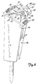
- the frame is usable on a wide variety of tools that now are pinned to linkages on the arm of a backhoe or excavator.
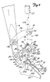
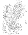
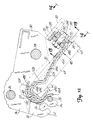
- the latch 41 is held in its "ready” position shown in Figure 1 when the quick attach bracket 24 is ready to be used, and while many latch holders can be used, as shown in Figures 2 and 3, a pivoting pawl 58 is mounted on a shaft 57, on at least one side of the latch.
- the pivoting pawl 58 aligns with a hub 44 of the frame latch 41 and as shown in Figure 3 the pawl 58 is positioned to engage a stop lug 59 integral with a hub 44.
- the stop lug has a stop surface 59A for holding the latch retracted in a retracted or release position.
- the pawl 58 is spring loaded with a torsion spring (not shown) to rotate in clockwise direction.
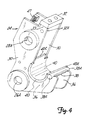
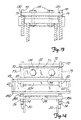
- Figures 12, 13 and 14 show a bolt or fastener connection for securing the frame 48 and bracket 24 together after they have been slid into position with nose bar 32 in receptacle 73 and channel 53 in saddle or retainer 40.
- the bracket and frame do not have to be fully seated, but nose bar 32 is close to its secured position.
- the latch 41, pawl 52, actuator 84 and spin 46 can all be removed from the bracket 24, no automatic latch is provided.
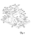
- the remaining parts are numbered as in the first forms of the invention.
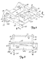
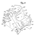
- the ears 70 have flat edge surfaces 79, on which end flanges 130 of a cross bar 132 rest.
- the cross bar 132 has a pair of bolt holes through which bolts 134 extend, and the bolts 134 are long enough to extend through aligning holes in the nose bar 32.
- the bolts 134 can be inserted through the aligning holes on the cross bar 132 and the nose bar 32 and tightened to securely hold the bracket and the frame 48 together.
- the nose bar 32 preferably will be spaced from the under surface of the cross bar 132 when the channel 53 first engages saddle 40 and the bolts 134 are first inserted.
Landscapes
- Engineering & Computer Science (AREA)
- Mechanical Engineering (AREA)
- Mining & Mineral Resources (AREA)
- Civil Engineering (AREA)
- General Engineering & Computer Science (AREA)
- Structural Engineering (AREA)
- Shovels (AREA)
- Automatic Assembly (AREA)
- Jib Cranes (AREA)
- Forklifts And Lifting Vehicles (AREA)
Claims (15)
- Rahmen (48) zur Befestigung an einem Schnellbefestigungsträger (24) auf einem Werkzeugarm (16), wobei der Rahmen ein Paar Rahmenseitenplatten (50, 50) und eine Querplatte (52) aufweist, welche die Seitenplatten (50, 50) verbindet und die Seitenplatten (50, 50) in beabstandeter Beziehung hält, wobei die Seitenplatten (50, 50) sich von der Querplatte (52) nach außen erstrecken, dadurch gekennzeichnet, daß die Querplatte (52) eine Kante (52C, 52F, 21A, 21B) aufweist, welche eine Halterung zum Sitz in einen Sattel (40) des Trägers (24) ausbildet, wobei die Seitenplatten beabstandet sind, um einen Endabschnitt (32) des von dem Sattel beabstandeten Trägers aufzunehmen, wenn die eine Kante (52C, 52F, 21A, 21B) in dem Sattel (40) gehalten wird, und daß eine Einrichtung (72) zum Sichern des Endabschnittes (32) des Trägers (24) in dem Rahmen (48) vorgesehen ist.
- Rahmen nach Anspruch 1, wobei die Seitenplatten (50, 50) Abschnitte aufweisen, die sich über die Querplatte (52) an einem Ende des Rahmens (48) angrenzend an die eine Kante (52C, 52F, 21A, 21B) hinaus erstrecken, wobei die Abschnitte der Seitenplatten (50, 50) Hakenaufnahmen (56) aufweisen, die darin für die Aufnahme einer Stützstange (38) ausgebildet sind.
- Rahmen nach Anspruch 1, wobei die Seitenplatten (50, 50) einen Halterungsschlitz mit einem sich zwischen den Seitenplatten (50, 50) erstreckenden Abschnitt der Querplatte (52) ausbilden, die Seitenplatten (50, 50) eine Breite des Schlitzes definieren, und die Einrichtung zum Sichern eine Stange (72) enthält, die von dem Abschnitt der Querplatte (52) beabstandet ist und im wesentlichen parallel zu der Querplatte (52) angeordnet ist und auf den Seitenplatten (50, 50) zur Begrenzung des Schlitzes abgestützt ist.
- Rahmen nach einem der Ansprüche 1 bis 3, wobei die eine Kante (52C, 52F, 21A, 21B) ein kanalförmiges Element aufweist, welches eine Basiswand (52C, 21A) aufweist, welche sich zwischen einer von einer Basiswand (52C) mit einer Verbindungswand (52F) ausgebildeten Ecke und einer Wand (21Bb) senkrecht zu der Basiswand (52C, 21A) erstreckt, wobei die Ecken dafür angepaßt sind, an Oberflächen des Sattels (40) anzugreifen.
- Rahmen nach Anspruch 1, wobei die Einrichtung für die Sicherung des Endabschnittes des Trägers Wände (72, 52, 50, 50) aufweist, welche einen Schlitz (73) an einer der einen Kante gegenüberliegenden Seite der Querplatte ausbilden.
- Rahmen nach einem der Ansprüche 1, 2, 3 oder 5 und ein Paar Abstandsträger (60, 90, 100, 114), welche auf der Querplatte (52) befestigt sind, wobei die Abstandsträger (60, 90, 100, 114) für den Sitz auf einem mit dem Rahmen (48) verwendbaren Werkzeug (96, 116) ausgebildet sind.
- Rahmen nach Anspruch 5, wobei der Schlitz eine sich zwischen den Seitenplatten (50, 50) erstreckende Breite aufweist und die eine Kante (52C, 52F, 21A, 21B) eine Krempe mit einer sich zwischen den Seitenplatten (50, 50) erstreckenden Breite aufweist, wobei der Abstand zwischen einer Eintrittsöffnung zu dem Schlitz (73) und der Krempe so ist, daß eine lineare Bewegung des Trägers (24) die Krempe (52C, 52F, 21A, 21B) und den Schlitz (73) mit Abschnitten des Trägers (24) in Eingriff bringt, auf welchem der Rahmen (48) befestigt ist.
- Rahmen nach Anspruch 6, wobei die Abstandsträger (60, 90, 100) im allgemeinen zu den Seitenplatten (50, 50) parallele Ebenen aufweisen und auf einer der Sicherungseinrichtung gegenüberliegenden Seite der Querplatte (52) angeordnet sind, wobei die Abstandsträger (60, 90, 100) sich so erstrecken, daß sie Verstärkungslagerungen für die eine Kante (52C, 52F, 21A, 21B) bereitstellen.
- Rahmen nach einem der vorstehenden Ansprüche, wobei die Querplatte (52) eine Plattenanordnung (55) aufweist, welche eine erste Platte (49) mit einer Öffnung (49a) dadurch und eine zweite Platte (52) aufweist, welche so ausgebildet ist, daß sie durch die Öffnung (49a) hervorsteht und eine Verriegelungsoberfläche (52b) bereit stellt, welche in Bezug auf die Ebene der ersten Platte (49) geneigt ist.
- Rahmen nach Anspruch 6, wobei der Abstandsträger (114) Befestigungslöcher darin zur Verbindung mit einem Werkzeug aufweist.
- Rahmen nach einem der Ansprüche 1 bis 3, ferner dadurch gekennzeichnet, daß der Rahmen (48) Wände hat, welche einen Halterungsschlitz (73) zwischen den Seitenplatten (50, 50) an einem der einen Kante (52C, 52F, 21A, 21B) gegenüberliegenden zweiten Ende der Querplatte (52) ausbilden, wobei der Schlitz (73) ein offenes Ende zwischen den Querplatten (52) aufweist, das in die Richtung der einen Kante (52C, 52F, 21A, 21B) weist, der Träger (24) eine Nasenquerstange (38) aufweist, welche in dem Schlitz (73) in einer Sitzposition aufgenommen wird, und mindestens ein Befestigungselement (134) zwischen dem Rahmen (48) und dem Träger (24), um den Rahmen (48) und den Träger (24) in einer Sitzposition zu halten.
- Rahmen nach einem der Ansprüche 1 bis 3, wobei ein Abschnitt der Querplatte (52) sich zwischen den Rahmenseitenplatten (50, 50) erstreckt und eine von dem Abschnitt der Querplatte (52) beabstandete und im wesentlichen parallel zu der Ebene der Querplatte (52) verlaufende Stange (72) auf den Rahmenseitenplatten (50, 50) gelagert ist, um einen Schlitz (73) zu bilden, ein Querelement (132) sich zwischen den Rahmenseitenplatten (50, 50) an einem Ende des Schlitzes (73) gegenüber dem offenen Ende erstreckt, und mindestens ein Gewindebefestigungselement (134) von dem Querelement (132) gelagert wird und mit dem Trägerendabschnitt in Eingriff bringbar ist, um eine Last auf den Endabschnitt (32) auszuüben, um den Rahmen (48) und den Träger (24) in die Sitzposition zu drücken.
- Rahmen nach Anspruch 11, wobei die Rahmenseitenplatten (50, 50) Endkanten (79) aufweisen, die im allgemeinen koplanar angrenzend an das zweite Ende der Querplatte (52) verlaufen, ein Querelement (132) auf den Endkanten (79) aufliegt und das mindestens eine Befestigungselement trägt, um eine Spannungsbelastung anzulegen, um einen Abschnitt des Trägers (24) in den Schlitz (73) zu dem Querelement (132) zu ziehen.
- Verfahren zur Sicherung eines Rahmens (48) an einem Schnellbefestigungsträger (24), der auf einem Werkzeugarm (16) befestigt ist, wobei der Träger (24) Abschnitte (40, 32) aufweist, welche den Rahmen (24) an mindestens zwei Stellen nach einer linearen Bewegung aufnehmen und verriegeln, einschließlich der Schritte einer linearen Verschiebung des Rahmens (48) und des Trägers (24) relativ zueinander, um den Rahmen (48) mit den Trägerabschnitten (40, 32) zu verriegeln, und den Rahmen (48) und den Träger (24) mit einem Befestigungselement (134) zusammenzuhalten, welches sich zwischen dem Rahmen (28) und dem Träger (24) erstreckt, und eine Kraft in der linearen Richtung auszuüben, um eine Verriegelung der Abschnitte des Rahmens (48) und des Trägers (24) zu erzwingen.
- Verfahren nach Anspruch 14, einschließlich des weiteren Schrittes einer Bereitstellung eines auf dem Rahmen (48) gelagerten Querelementes (132) mit einer Durchgangsöffnung, Durchführen des Befestigungselementes (134) durch die Öffnung und schraubendes Anziehen des Befestigungselementes, um den Träger (24) und den Rahmen (48) aneinander zu ziehen.
Applications Claiming Priority (5)
| Application Number | Priority Date | Filing Date | Title |
|---|---|---|---|
| US814313 | 1997-03-10 | ||
| US08/814,313 US5974706A (en) | 1997-03-10 | 1997-03-10 | Attachment construction for earthworking implement |
| US09/028,074 US6163989A (en) | 1997-03-10 | 1998-02-23 | Frame for mounting on a boom mounted quick change bracket |
| US28074 | 1998-02-23 | ||
| PCT/US1998/004454 WO1998040569A1 (en) | 1997-03-10 | 1998-03-06 | Frame for mounting on a boom mounted quick change bracket |
Publications (2)
| Publication Number | Publication Date |
|---|---|
| EP0904466A1 EP0904466A1 (de) | 1999-03-31 |
| EP0904466B1 true EP0904466B1 (de) | 2001-09-26 |
Family
ID=26703270
Family Applications (1)
| Application Number | Title | Priority Date | Filing Date |
|---|---|---|---|
| EP98910214A Expired - Lifetime EP0904466B1 (de) | 1997-03-10 | 1998-03-06 | Rahmen zum Anbringen einer an einem Ausleger befestigten Schnellwechselvorrichtung |
Country Status (7)
| Country | Link |
|---|---|
| US (1) | US6163989A (de) |
| EP (1) | EP0904466B1 (de) |
| AU (1) | AU735280B2 (de) |
| CA (1) | CA2252766C (de) |
| DE (1) | DE69801793T2 (de) |
| ES (1) | ES2162424T3 (de) |
| WO (1) | WO1998040569A1 (de) |
Cited By (1)
| Publication number | Priority date | Publication date | Assignee | Title |
|---|---|---|---|---|
| WO2007006108A1 (fr) * | 2005-07-14 | 2007-01-18 | Agri-System Sprl | Ensemble de fixation rapide |
Families Citing this family (31)
| Publication number | Priority date | Publication date | Assignee | Title |
|---|---|---|---|---|
| US6000154A (en) * | 1997-03-10 | 1999-12-14 | Clark Equipment Company | Quick change attachment for powered auxiliary tool |
| GB2330570B (en) * | 1998-09-08 | 1999-09-15 | Miller Ronald Keith | Quick coupler for bucket excavators |
| GB2359062B (en) * | 2000-02-11 | 2002-01-02 | Ronald Keith Miller | Universal coupler for bucket excavators |
| US7337564B2 (en) * | 2000-10-23 | 2008-03-04 | Jrb Attachments, Llc | Loader coupler or other attachment with adjustable stops |
| US6886279B2 (en) * | 2000-10-23 | 2005-05-03 | Jrb Company, Inc. | Loader coupler with adjustable dump and roll-back stops |
| US6539650B2 (en) | 2000-12-05 | 2003-04-01 | Clark Equipment Company | Swivel mounting for quick attachment bracket |
| USD455762S1 (en) | 2000-12-05 | 2002-04-16 | Clark Equipment Company | Quick attachment swivel bracket |
| US6662681B2 (en) | 2002-01-14 | 2003-12-16 | Kent Demolition, Inc. | Connector assembly for mounting an implement to a prime mover |
| ITBO20030056A1 (it) * | 2003-02-07 | 2004-08-08 | Cangini Benne Srl | Dispositivo di connessione per utensili. |
| FI121223B (fi) * | 2004-07-01 | 2010-08-31 | Sandvik Mining & Constr Oy | Rikotusvasara, rikotusvasaran kiinnityskappale, rikotusvasaran sivulevy sekä rikotusvasaran suojakotelo |
| US7329082B2 (en) * | 2004-09-21 | 2008-02-12 | Ultra-Tach, Llc | Electrically actuated attachment system for tractor front end loaders |
| US7090280B2 (en) * | 2004-10-22 | 2006-08-15 | Willey Barry A | Mounting system for accessories |
| DK1852555T3 (da) | 2006-05-02 | 2012-10-08 | Kinshofer Gmbh | Sikkerhedslåseindretning til en lynkobling |
| WO2008031590A2 (en) | 2006-09-13 | 2008-03-20 | Ian Hill | Coupler for excavators |
| CA2573703A1 (en) * | 2007-01-11 | 2008-07-11 | Denis Laurent | Vibration damping mounting |
| US7984575B2 (en) | 2007-07-05 | 2011-07-26 | Caterpillar Inc. | Quick coupler assembly |
| GB0816335D0 (en) | 2008-09-08 | 2008-10-15 | Hill Ian | Coupler with gravity operated safety device |
| USD630268S1 (en) * | 2009-11-25 | 2011-01-04 | John Cunningham | Remote controlled vehicle |
| GB201010269D0 (en) | 2010-06-18 | 2010-08-04 | Hill Ian | Hydraulic coupler with attachment pin retention system |
| WO2011035883A1 (en) | 2009-09-22 | 2011-03-31 | Ian Hill | Hydraulic coupler with pin retention system for coupling an attachment to a work machine |
| GB2474572B (en) | 2009-10-16 | 2014-11-26 | Hill Engineering Ltd | Control system for a hydraulic coupler |
| GB2474576B (en) | 2009-10-16 | 2014-03-19 | Ian Hill | Coupler |
| US8974137B2 (en) | 2011-12-22 | 2015-03-10 | Caterpillar Inc. | Quick coupler |
| US8684623B2 (en) | 2012-05-30 | 2014-04-01 | Caterpillar Inc. | Tool coupler having anti-release mechanism |
| US8869437B2 (en) | 2012-05-30 | 2014-10-28 | Caterpillar Inc. | Quick coupler |
| US9217235B2 (en) | 2012-05-30 | 2015-12-22 | Caterpillar Inc. | Tool coupler system having multiple pressure sources |
| US9228314B2 (en) | 2013-05-08 | 2016-01-05 | Caterpillar Inc. | Quick coupler hydraulic control system |
| US10808378B2 (en) * | 2017-01-31 | 2020-10-20 | Stanley Black & Decker, Inc. | Tool-to-carrier cradle assembly |
| WO2019241735A1 (en) * | 2018-06-15 | 2019-12-19 | Arrow Acquisition, Llc | Quick connect system for industrial and construction equipment |
| DE102020115814A1 (de) | 2020-06-16 | 2021-12-16 | Liebherr-Hydraulikbagger Gmbh | Baggerlöffel mit Verstärkung |
| US12601151B2 (en) | 2022-10-06 | 2026-04-14 | Caterpillar Inc. | Universal hydraulic connecting quick coupler system |
Family Cites Families (36)
| Publication number | Priority date | Publication date | Assignee | Title |
|---|---|---|---|---|
| US2963183A (en) * | 1957-09-25 | 1960-12-06 | Warner Swasey Co | Material handling machines having boom with detachable tool |
| US3237795A (en) * | 1964-09-24 | 1966-03-01 | Erickson Power Lift Trucks Inc | Means for detachably securing work heads to boom-equipped power trucks and the like |
| BE791834A (nl) * | 1971-12-01 | 1973-03-16 | Verachtert Antonius P | Graafmachine |
| GB1582398A (en) * | 1976-07-05 | 1981-01-07 | Komatsu Mfg Co Ltd | Vehicle for releasably carrying an implement |
| SU763531A1 (ru) * | 1977-10-25 | 1980-09-15 | Кабардино-Балкарский государственный университет | Устройство дл креплени ковша экскаватора |
| US4214840A (en) * | 1979-01-18 | 1980-07-29 | J. H. Beales Steel Fabricators, Ltd. | Quick-release coupler |
| US4225283A (en) * | 1979-02-15 | 1980-09-30 | J. I. Case Company | Backhoe bucket quick coupling |
| NL170447C (nl) * | 1979-06-01 | 1984-03-16 | Bofors Nederland | Inrichting voor het koppelen van een gereedschap aan een giek met behulp van een tussenstuk en een koppelstuk. |
| FR2475160A1 (fr) * | 1980-01-31 | 1981-08-07 | Pingon Pierre De | Dispositif formant prise d'outils automatique pour excavateur, chargeur, machine de terrassement ou autres |
| NZ199611A (en) * | 1981-02-05 | 1984-09-28 | Maroochy Shire Council | Quick release and attachment assembly for construction equipment tools |
| SE421984B (sv) * | 1981-04-15 | 1982-02-15 | Tunamatic Hb | Kopplingsanordning for redskap till en traktor |
| DE3312442C2 (de) * | 1983-04-07 | 1986-05-28 | Karl Schaeff GmbH & Co, Maschinenfabrik, 7183 Langenburg | Schnellwechselvorrichtung für Arbeitswerkzeuge an einem Baggerausleger |
| GB8500911D0 (en) * | 1985-01-15 | 1985-02-20 | Mason S T | Quick-change fitting |
| JPS6393934A (ja) * | 1986-10-03 | 1988-04-25 | スチユア−ト.アレキサンダ−.エセツクス | 建設機械用連結組立体 |
| NZ222864A (en) * | 1987-06-04 | 1991-02-26 | William John Balemi | Connector for attaching implements to vehicle boom |
| SE458534B (sv) * | 1987-07-20 | 1989-04-10 | Lidkoeping Svets & Maskinprod | Anordning vid en snabbkoppling foer loesbar sammankoppling av ett arbetsredskap och en graevmaskins manoeverarm |
| CH675266A5 (de) * | 1987-12-22 | 1990-09-14 | Zepf Hans Rudolf | |
| US4929143A (en) * | 1989-01-31 | 1990-05-29 | Gehl Company | Quick-attaching mechanism |
| DE9000721U1 (de) * | 1990-01-24 | 1990-03-01 | Nagler, Jürgen, 5804 Herdecke | Schnellkupplung eines Arbeitsvorsatzes an Baggern |
| GB9005074D0 (en) * | 1990-03-07 | 1990-05-02 | Aubrey Martin J | Coupling |
| DE4026210C2 (de) * | 1990-08-18 | 1994-08-11 | Ahlmann Maschinenbau Gmbh | Schnellwechselvorrichtung |
| US5415235A (en) * | 1990-10-12 | 1995-05-16 | Jrb Company, Inc. | Cam locking coupler system |
| US5107610A (en) * | 1991-01-22 | 1992-04-28 | Nicholas Fusco | Quick-coupling connector for backhoes and the like |
| US5098252A (en) * | 1991-02-04 | 1992-03-24 | Ford New Holland, Inc. | Skid steer loader adaptor |
| US5597283A (en) * | 1991-04-09 | 1997-01-28 | Jones; Gordon | Quick coupling for heavy equipment attachment |
| US5147173A (en) * | 1991-06-03 | 1992-09-15 | Caterpillar Inc. | Coupling device |
| US5145313A (en) * | 1991-06-28 | 1992-09-08 | Weyer Paul P | Quick disconnect bucket actuator |
| NL9101150A (nl) * | 1991-07-02 | 1993-02-01 | Verachtert Bv | Koppelstuk. |
| FR2690718B1 (fr) * | 1992-05-04 | 1994-06-17 | Groupe Pel Job | Dispositif de securite pour prise automatique d'outils, en particulier pour machines de terrassement ou analogue. |
| DE4214569C2 (de) * | 1992-05-08 | 2001-12-20 | Lehnhoff Hartstahl Gmbh & Co | Schnellwechselvorrichtung |
| CA2072342C (en) * | 1992-06-26 | 1994-06-14 | Robert D. Jenkins | Quick coupling arrangement for excavator buckets and the like |
| US5332353A (en) * | 1993-02-16 | 1994-07-26 | Wain Roy, Inc. | Quick coupler for excavation equipment |
| FR2708679B1 (fr) * | 1993-08-06 | 1995-09-01 | Pel Job Groupe | Dispositif pour prise automatique d'outil pour engin de terrassement ou analogue. |
| FR2717516B1 (fr) * | 1994-03-16 | 1996-05-03 | Pel Job Groupe | Dispositif pour permettre la prise automatique d'outils, notamment pour engins de terrassement ou analogue. |
| JP2793165B2 (ja) * | 1996-02-06 | 1998-09-03 | 甲南電機株式会社 | 油圧ショベルのアタッチメント着脱装置 |
| US5727342A (en) * | 1996-04-18 | 1998-03-17 | Wain-Roy, Inc. | Hydraulic latch pin assembly for coupling a tool to a construction equipment |
-
1998
- 1998-02-23 US US09/028,074 patent/US6163989A/en not_active Expired - Lifetime
- 1998-03-06 CA CA002252766A patent/CA2252766C/en not_active Expired - Lifetime
- 1998-03-06 EP EP98910214A patent/EP0904466B1/de not_active Expired - Lifetime
- 1998-03-06 WO PCT/US1998/004454 patent/WO1998040569A1/en not_active Ceased
- 1998-03-06 DE DE69801793T patent/DE69801793T2/de not_active Expired - Fee Related
- 1998-03-06 ES ES98910214T patent/ES2162424T3/es not_active Expired - Lifetime
- 1998-03-06 AU AU64511/98A patent/AU735280B2/en not_active Ceased
Cited By (1)
| Publication number | Priority date | Publication date | Assignee | Title |
|---|---|---|---|---|
| WO2007006108A1 (fr) * | 2005-07-14 | 2007-01-18 | Agri-System Sprl | Ensemble de fixation rapide |
Also Published As
| Publication number | Publication date |
|---|---|
| CA2252766A1 (en) | 1998-09-17 |
| CA2252766C (en) | 2006-07-11 |
| DE69801793D1 (de) | 2001-10-31 |
| AU735280B2 (en) | 2001-07-05 |
| AU6451198A (en) | 1998-09-29 |
| EP0904466A1 (de) | 1999-03-31 |
| US6163989A (en) | 2000-12-26 |
| WO1998040569A1 (en) | 1998-09-17 |
| ES2162424T3 (es) | 2001-12-16 |
| DE69801793T2 (de) | 2002-06-13 |
Similar Documents
| Publication | Publication Date | Title |
|---|---|---|
| CA2252766C (en) | Frame for mounting on a boom mounted quick change bracket | |
| US5983535A (en) | Fastener secured frame for boom mounted quick change bracket | |
| US5974706A (en) | Attachment construction for earthworking implement | |
| US6499934B1 (en) | Implement attachment bracket for skid steer loader mounting plate | |
| US6058633A (en) | Quick coupling device and method utilizing an over-center spring | |
| US5179794A (en) | Semi-automatic coupling apparatus | |
| EP1254287B1 (de) | Universale kupplungsvorrichtung für baggerlöffel | |
| US7984575B2 (en) | Quick coupler assembly | |
| US5951192A (en) | Quick connect system for excavator buckets | |
| US5813822A (en) | Bucket and thumb combination as a quick decoupling attachment | |
| CA2261468C (en) | Quick change attachment for powered auxiliary tool | |
| US6481124B1 (en) | Quick coupler for bucket excavators | |
| US4854813A (en) | Coupling apparatus | |
| GB2306439A (en) | Quick coupling device | |
| US7934758B2 (en) | Systems and methods for connecting and adapting a grapple assembly | |
| US20070201973A1 (en) | Quick coupler system | |
| CA2261452C (en) | Frame for mounting on a boom mounted quick change bracket | |
| US10767339B2 (en) | Multiple interface tool for a construction machine | |
| CA2261467C (en) | Fastener secured frame for boom mounted quick change bracket | |
| EP0198840B1 (de) | Verbindungsvorrichtung | |
| WO2001096672A1 (en) | Latch bar construction for a quick change bracket | |
| CN117897536A (zh) | 作业机 | |
| US20050207836A1 (en) | Quick coupler system | |
| GB2634304A (en) | Apparatus and method for connecting a dangling tool to a quick coupler | |
| JPH0687449U (ja) | アタッチメント取付装置 |
Legal Events
| Date | Code | Title | Description |
|---|---|---|---|
| PUAI | Public reference made under article 153(3) epc to a published international application that has entered the european phase |
Free format text: ORIGINAL CODE: 0009012 |
|
| AK | Designated contracting states |
Kind code of ref document: A1 Designated state(s): BE DE ES FR GB IT |
|
| 17P | Request for examination filed |
Effective date: 19990303 |
|
| 17Q | First examination report despatched |
Effective date: 19991015 |
|
| GRAG | Despatch of communication of intention to grant |
Free format text: ORIGINAL CODE: EPIDOS AGRA |
|
| GRAG | Despatch of communication of intention to grant |
Free format text: ORIGINAL CODE: EPIDOS AGRA |
|
| GRAG | Despatch of communication of intention to grant |
Free format text: ORIGINAL CODE: EPIDOS AGRA |
|
| GRAH | Despatch of communication of intention to grant a patent |
Free format text: ORIGINAL CODE: EPIDOS IGRA |
|
| GRAH | Despatch of communication of intention to grant a patent |
Free format text: ORIGINAL CODE: EPIDOS IGRA |
|
| GRAA | (expected) grant |
Free format text: ORIGINAL CODE: 0009210 |
|
| AK | Designated contracting states |
Kind code of ref document: B1 Designated state(s): BE DE ES FR GB IT |
|
| REF | Corresponds to: |
Ref document number: 69801793 Country of ref document: DE Date of ref document: 20011031 |
|
| REG | Reference to a national code |
Ref country code: ES Ref legal event code: FG2A Ref document number: 2162424 Country of ref document: ES Kind code of ref document: T3 |
|
| REG | Reference to a national code |
Ref country code: GB Ref legal event code: IF02 |
|
| ET | Fr: translation filed | ||
| PGFP | Annual fee paid to national office [announced via postgrant information from national office to epo] |
Ref country code: GB Payment date: 20020501 Year of fee payment: 5 Ref country code: FR Payment date: 20020501 Year of fee payment: 5 |
|
| PGFP | Annual fee paid to national office [announced via postgrant information from national office to epo] |
Ref country code: DE Payment date: 20020502 Year of fee payment: 5 |
|
| PGFP | Annual fee paid to national office [announced via postgrant information from national office to epo] |
Ref country code: ES Payment date: 20020509 Year of fee payment: 5 |
|
| PGFP | Annual fee paid to national office [announced via postgrant information from national office to epo] |
Ref country code: BE Payment date: 20020606 Year of fee payment: 5 |
|
| PLBE | No opposition filed within time limit |
Free format text: ORIGINAL CODE: 0009261 |
|
| STAA | Information on the status of an ep patent application or granted ep patent |
Free format text: STATUS: NO OPPOSITION FILED WITHIN TIME LIMIT |
|
| 26N | No opposition filed | ||
| PG25 | Lapsed in a contracting state [announced via postgrant information from national office to epo] |
Ref country code: GB Free format text: LAPSE BECAUSE OF NON-PAYMENT OF DUE FEES Effective date: 20030306 |
|
| PG25 | Lapsed in a contracting state [announced via postgrant information from national office to epo] |
Ref country code: ES Free format text: LAPSE BECAUSE OF NON-PAYMENT OF DUE FEES Effective date: 20030307 |
|
| PG25 | Lapsed in a contracting state [announced via postgrant information from national office to epo] |
Ref country code: BE Free format text: LAPSE BECAUSE OF NON-PAYMENT OF DUE FEES Effective date: 20030331 |
|
| BERE | Be: lapsed |
Owner name: *CLARK EQUIPMENT CY Effective date: 20030331 |
|
| PG25 | Lapsed in a contracting state [announced via postgrant information from national office to epo] |
Ref country code: DE Free format text: LAPSE BECAUSE OF NON-PAYMENT OF DUE FEES Effective date: 20031001 |
|
| GBPC | Gb: european patent ceased through non-payment of renewal fee |
Effective date: 20030306 |
|
| PG25 | Lapsed in a contracting state [announced via postgrant information from national office to epo] |
Ref country code: FR Free format text: LAPSE BECAUSE OF NON-PAYMENT OF DUE FEES Effective date: 20031127 |
|
| REG | Reference to a national code |
Ref country code: FR Ref legal event code: ST |
|
| REG | Reference to a national code |
Ref country code: ES Ref legal event code: FD2A Effective date: 20030307 |
|
| PG25 | Lapsed in a contracting state [announced via postgrant information from national office to epo] |
Ref country code: IT Free format text: LAPSE BECAUSE OF NON-PAYMENT OF DUE FEES Effective date: 20050306 |