EP0904466B1 - Chassis de montage de chaise d'echange rapide sur un bras articule - Google Patents
Chassis de montage de chaise d'echange rapide sur un bras articule Download PDFInfo
- Publication number
- EP0904466B1 EP0904466B1 EP98910214A EP98910214A EP0904466B1 EP 0904466 B1 EP0904466 B1 EP 0904466B1 EP 98910214 A EP98910214 A EP 98910214A EP 98910214 A EP98910214 A EP 98910214A EP 0904466 B1 EP0904466 B1 EP 0904466B1
- Authority
- EP
- European Patent Office
- Prior art keywords
- frame
- bracket
- side plates
- plate
- slot
- Prior art date
- Legal status (The legal status is an assumption and is not a legal conclusion. Google has not performed a legal analysis and makes no representation as to the accuracy of the status listed.)
- Expired - Lifetime
Links
Images


Classifications
-
- E—FIXED CONSTRUCTIONS
- E02—HYDRAULIC ENGINEERING; FOUNDATIONS; SOIL SHIFTING
- E02F—DREDGING; SOIL-SHIFTING
- E02F3/00—Dredgers; Soil-shifting machines
- E02F3/04—Dredgers; Soil-shifting machines mechanically-driven
- E02F3/28—Dredgers; Soil-shifting machines mechanically-driven with digging tools mounted on a dipper- or bucket-arm, i.e. there is either one arm or a pair of arms, e.g. dippers, buckets
- E02F3/36—Component parts
- E02F3/3604—Devices to connect tools to arms, booms or the like
- E02F3/3609—Devices to connect tools to arms, booms or the like of the quick acting type, e.g. controlled from the operator seat
- E02F3/3622—Devices to connect tools to arms, booms or the like of the quick acting type, e.g. controlled from the operator seat with a hook and a locking element acting on a pin
-
- E—FIXED CONSTRUCTIONS
- E02—HYDRAULIC ENGINEERING; FOUNDATIONS; SOIL SHIFTING
- E02F—DREDGING; SOIL-SHIFTING
- E02F3/00—Dredgers; Soil-shifting machines
- E02F3/04—Dredgers; Soil-shifting machines mechanically-driven
- E02F3/28—Dredgers; Soil-shifting machines mechanically-driven with digging tools mounted on a dipper- or bucket-arm, i.e. there is either one arm or a pair of arms, e.g. dippers, buckets
- E02F3/36—Component parts
- E02F3/3604—Devices to connect tools to arms, booms or the like
- E02F3/3609—Devices to connect tools to arms, booms or the like of the quick acting type, e.g. controlled from the operator seat
- E02F3/3627—Devices to connect tools to arms, booms or the like of the quick acting type, e.g. controlled from the operator seat with a hook and a longitudinal locking element
-
- E—FIXED CONSTRUCTIONS
- E02—HYDRAULIC ENGINEERING; FOUNDATIONS; SOIL SHIFTING
- E02F—DREDGING; SOIL-SHIFTING
- E02F3/00—Dredgers; Soil-shifting machines
- E02F3/04—Dredgers; Soil-shifting machines mechanically-driven
- E02F3/28—Dredgers; Soil-shifting machines mechanically-driven with digging tools mounted on a dipper- or bucket-arm, i.e. there is either one arm or a pair of arms, e.g. dippers, buckets
- E02F3/36—Component parts
- E02F3/3604—Devices to connect tools to arms, booms or the like
- E02F3/3609—Devices to connect tools to arms, booms or the like of the quick acting type, e.g. controlled from the operator seat
- E02F3/364—Devices to connect tools to arms, booms or the like of the quick acting type, e.g. controlled from the operator seat using wedges
-
- E—FIXED CONSTRUCTIONS
- E02—HYDRAULIC ENGINEERING; FOUNDATIONS; SOIL SHIFTING
- E02F—DREDGING; SOIL-SHIFTING
- E02F3/00—Dredgers; Soil-shifting machines
- E02F3/04—Dredgers; Soil-shifting machines mechanically-driven
- E02F3/28—Dredgers; Soil-shifting machines mechanically-driven with digging tools mounted on a dipper- or bucket-arm, i.e. there is either one arm or a pair of arms, e.g. dippers, buckets
- E02F3/36—Component parts
- E02F3/3604—Devices to connect tools to arms, booms or the like
- E02F3/3609—Devices to connect tools to arms, booms or the like of the quick acting type, e.g. controlled from the operator seat
- E02F3/3645—Devices to connect tools to arms, booms or the like of the quick acting type, e.g. controlled from the operator seat with auto-engagement means for automatic snap-on of the tool coupler part
-
- E—FIXED CONSTRUCTIONS
- E02—HYDRAULIC ENGINEERING; FOUNDATIONS; SOIL SHIFTING
- E02F—DREDGING; SOIL-SHIFTING
- E02F3/00—Dredgers; Soil-shifting machines
- E02F3/04—Dredgers; Soil-shifting machines mechanically-driven
- E02F3/28—Dredgers; Soil-shifting machines mechanically-driven with digging tools mounted on a dipper- or bucket-arm, i.e. there is either one arm or a pair of arms, e.g. dippers, buckets
- E02F3/36—Component parts
- E02F3/3604—Devices to connect tools to arms, booms or the like
- E02F3/3609—Devices to connect tools to arms, booms or the like of the quick acting type, e.g. controlled from the operator seat
- E02F3/365—Devices to connect tools to arms, booms or the like of the quick acting type, e.g. controlled from the operator seat with redundant latching means, e.g. for safety purposes
-
- E—FIXED CONSTRUCTIONS
- E02—HYDRAULIC ENGINEERING; FOUNDATIONS; SOIL SHIFTING
- E02F—DREDGING; SOIL-SHIFTING
- E02F3/00—Dredgers; Soil-shifting machines
- E02F3/04—Dredgers; Soil-shifting machines mechanically-driven
- E02F3/28—Dredgers; Soil-shifting machines mechanically-driven with digging tools mounted on a dipper- or bucket-arm, i.e. there is either one arm or a pair of arms, e.g. dippers, buckets
- E02F3/36—Component parts
- E02F3/3604—Devices to connect tools to arms, booms or the like
- E02F3/3686—Devices to connect tools to arms, booms or the like using adapters, i.e. additional element to mount between the coupler and the tool
-
- E—FIXED CONSTRUCTIONS
- E02—HYDRAULIC ENGINEERING; FOUNDATIONS; SOIL SHIFTING
- E02F—DREDGING; SOIL-SHIFTING
- E02F3/00—Dredgers; Soil-shifting machines
- E02F3/04—Dredgers; Soil-shifting machines mechanically-driven
- E02F3/28—Dredgers; Soil-shifting machines mechanically-driven with digging tools mounted on a dipper- or bucket-arm, i.e. there is either one arm or a pair of arms, e.g. dippers, buckets
- E02F3/36—Component parts
- E02F3/40—Dippers; Buckets ; Grab devices, e.g. manufacturing processes for buckets, form, geometry or material of buckets
-
- Y—GENERAL TAGGING OF NEW TECHNOLOGICAL DEVELOPMENTS; GENERAL TAGGING OF CROSS-SECTIONAL TECHNOLOGIES SPANNING OVER SEVERAL SECTIONS OF THE IPC; TECHNICAL SUBJECTS COVERED BY FORMER USPC CROSS-REFERENCE ART COLLECTIONS [XRACs] AND DIGESTS
- Y10—TECHNICAL SUBJECTS COVERED BY FORMER USPC
- Y10S—TECHNICAL SUBJECTS COVERED BY FORMER USPC CROSS-REFERENCE ART COLLECTIONS [XRACs] AND DIGESTS
- Y10S37/00—Excavating
- Y10S37/903—Scoop or scraper attachments
Definitions
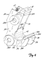
- the frame is usable on a wide variety of tools that now are pinned to linkages on the arm of a backhoe or excavator.
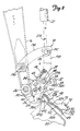
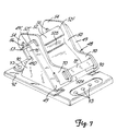
- the latch 41 is held in its "ready” position shown in Figure 1 when the quick attach bracket 24 is ready to be used, and while many latch holders can be used, as shown in Figures 2 and 3, a pivoting pawl 58 is mounted on a shaft 57, on at least one side of the latch.
- the pivoting pawl 58 aligns with a hub 44 of the frame latch 41 and as shown in Figure 3 the pawl 58 is positioned to engage a stop lug 59 integral with a hub 44.
- the stop lug has a stop surface 59A for holding the latch retracted in a retracted or release position.
- the pawl 58 is spring loaded with a torsion spring (not shown) to rotate in clockwise direction.
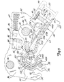
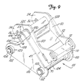
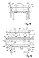
- Figures 12, 13 and 14 show a bolt or fastener connection for securing the frame 48 and bracket 24 together after they have been slid into position with nose bar 32 in receptacle 73 and channel 53 in saddle or retainer 40.
- the bracket and frame do not have to be fully seated, but nose bar 32 is close to its secured position.
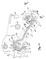
- the latch 41, pawl 52, actuator 84 and spin 46 can all be removed from the bracket 24, no automatic latch is provided.
- the remaining parts are numbered as in the first forms of the invention.
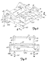
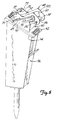
- the ears 70 have flat edge surfaces 79, on which end flanges 130 of a cross bar 132 rest.
- the cross bar 132 has a pair of bolt holes through which bolts 134 extend, and the bolts 134 are long enough to extend through aligning holes in the nose bar 32.
- the bolts 134 can be inserted through the aligning holes on the cross bar 132 and the nose bar 32 and tightened to securely hold the bracket and the frame 48 together.
- the nose bar 32 preferably will be spaced from the under surface of the cross bar 132 when the channel 53 first engages saddle 40 and the bolts 134 are first inserted.
Landscapes
- Engineering & Computer Science (AREA)
- Mechanical Engineering (AREA)
- Mining & Mineral Resources (AREA)
- Civil Engineering (AREA)
- General Engineering & Computer Science (AREA)
- Structural Engineering (AREA)
- Shovels (AREA)
- Automatic Assembly (AREA)
- Jib Cranes (AREA)
- Forklifts And Lifting Vehicles (AREA)
Abstract
Claims (15)
- Châssis (48) de fixation à un support (24) de fixation rapide sur un bras d'accessoire (16), le châssis (48) comportant une paire de plaques latérales (50, 50) de châssis et une plaque transversale (52) raccordant les plaques latérales (50, 50) et maintenant les plaques latérales (50, 50) à distance, les plaques latérales (50, 50) s'étendant vers l'extérieur de la plaque transversale (52), caractérisé en ce que la plaque transversale (52) a un bord (52C, 52F, 21A, 21B) formant un organe de retenue pour le montage dans une selle (40) du support (24), les plaques latérales étant espacées afin qu'elles logent une partie d'extrémité (32) du support à distance de la selle lorsque la premier bord (52C, 52P, 21A, 21B) est retenu dans la selle (40), et un dispositif (72) de fixation de la partie d'extrémité (32) du support (24) dans le châssis (48).
- Châssis selon la revendication 1, dans lequel les plaques latérales (50, 50) ont des parties qui s'étendent au-delà de la plaque transversale (52) à une extrémité du châssis (48) adjacente au premier bord (52C, 52F, 21A, 21B), lesdites parties des plaques latérales (50, 50) ayant des réceptacles (56) pour crochet formés à l'intérieur pour le logement d'une tige de support (38).
- Châssis selon la revendication 1, dans lequel les plaques latérales (50, 50) forment une fente d'organe de retenue avec une partie de la plaque transversale (52) qui s'étend entre les plaques latérales (50, 50), les plaques latérales (50, 50) délimitant la largeur de la fente, et le dispositif de fixation comprend une barre (72) distante de la partie de plaque transversale (52) et positionnée en direction pratiquement paralièle à la plaque transversale (52) et supportée sur les plaques latérales (50, 50) pour la délimitation de la fente.
- Châssis selon l'une quelconque des revendications 1 a 3, dans lequel ledit bord (52C, 52F, 21A, 21B) comporte un organe en forme de canal qui comprend une paroi de base (52C, 21A) qui s'étend entre un coin formé par la paroi de base (52C) et une paroi de jonction (52F) et une paroi (21B) perpendiculaire à la paroi de base (52C, 21A), les coins étant destinés à coopérer avec des surfaces de la selle (40).
- Châssis selon la revendication 1, dans lequel le dispositif de fixation de la partie d'extrémité du support comprend les parois (72, 52, 50, 50) formant une fente (73) d'un côté opposé de la plaque transversale par rapport au premier bord.
- Châssis selon l'une quelconque des revendications 1, 2, 3 et 5, avec une paire de supports distants (60, 90, 100, 114) montée sur la plaque transversale (52), les supports distants (60, 90, 100, 114) étant formés afin qu'ils s'ajustent sur un outil (96, 116) qui peut être utilisé avec le châssis (48).
- Châssis selon la revendication 5, dans lequel la fente a une largeur entre les plaques latérales (50, 50), et ledit bord (52C, 52F, 21A, 21B) comprend un rebord ayant une largeur disposée entre les plaques latérales (50, 50), l'espacement d'une ouverture d'entrée dans la fente (73) et du rebord étant tel qu'un mouvement linéaire du support (24) met le rebord (52C, 52F, 21A, 21B) et la fente (73) tous deux au contact de parties du support (24) sur lesquelles le châssis (48) est monté.
- Châssis selon la revendication 6, dans lequel les supports distants (60, 90, 100) ont des plans parallèles de façon générale aux plaques latérales (50, 50) et sont placés du côté de la plaque latérale (52) opposé au dispositif de fixation, les supports distants (60, 90, 100). s'étendant afin qu'ils forment des supports de renforcement dudit bord (52C, 52F, 21A, 21B).
- Châssis selon l'une quelconque des revendications précédentes, dans lequel la plaque transversale (52) comprend un ensemble à plaque (55) qui comporte une première plaque (49) ayant une ouverture (49A) qui la traverse, et une seconde plaque (52) formée afin qu'elle passe par l'ouverture (49A) et constituant une surface de verrouillage (52B) inclinée par rapport au plan de la première plaque (49).
- Châssis selon la revendication 6, dans lequel le support distant (114) a des ouvertures de montage destinées au couplage à un outil.
- Châssis selon l'une quelconque des revendications 1 à 3, caractérisé en outre par un châssis (48) ayant des parois formant une fente d'organe de retenue (73) entre les plaques latérales (50, 50) à une seconde extrémité de la plaque transversale (52) qui est opposée audit bord (52C, 52F, 21A, 21B), la fente (73) ayant une extrémité ouverte entre les plaques transversales (52) tournées vers le bord (52C, 52F, 21A, 21B), le support (24) ayant une barre transversale de nez (38) logée dans la fente (73) en position assise et au moine un organe de fixation (134) placé entre le châssis (48) et le support (24) afin que le châssis (48) et le support (24) soient maintenus en position assise.
- Châssis selon l'une quelconque des revendications 1 à 3, dans lequel une partie de la plaque transversale (52) qui s'étend entre les plaques latérales (50, 50) du châssis et une barre (72) distante de la partie de plaque transversale (52) et pratiquement parallèle au plan de la plaque transversale (52) sont supportées sur les plaques latérales (50, 50) du châssis pour la formation d'une fente (73), un organe transversale (132) s'étendant entre les plaques latérales (50, 50) du châssis à une extrémité de la fente (73) opposée à l'extrémité ouverte, et au moins un organe fileté de fixation (134) supporté sur l'organe transversale (132) est destiné à coopérer avec la partie d'extrémité de support pour exercer une charge sur la partie d'extrémité (32) et repousser le châssis (48) et le support (24) vers la position assise.
- Châssis selon la revendication 11, dans lequel les plaques latérales (50, 50) du châssis ont des bords d'extrémité (79) qui sont coplanaires de façon générale près de la seconde extrémité de la plaque transversale (52), et un organe transversal (132) en appui sur les bords d'extrémité (79) et portant l'organe de fixation au moins pour l'application d'une force de traction destinée à tirer une partie du support (24) dans la fente (73) vers l'organe transversale (132).
- Procédé de fixation d'un châssis (48) à un support (24) à fixation rapide monté sur un bras d'accessoire (16), le support (24) ayant des parties (40, 32) qui logent le châssis (24) et sont imbriquées avec celui-ci à au moins deux emplacements lors d'un déplacement linéaire, comprenant les étapes suivantes : le déplacement linéaire du châssis (48) et du support (24) l'un par rapport à l'autre afin que le châssis (48) soit emboíté dans les parties de support (40, 32), et la fixation du châssis (48) et du support (24) l'un à l'autre par un organe de fixation (134) qui s'étend entre le châssis (28) et le support (24) et qui exerce une force en direction linéaire afin que les parties de châssis (48) et de support (24) soient repoussées en position de coopération.
- Procédé selon la revendication 14, comprenant en outre des étapes de disposition d'un organe transversal (132) supporté par le châssis (48), ayant une ouverture qui le traverse, de passage de l'organe de fixation (134) dans cette ouverture, et de serrage par vissage de l'organe de fixation afin que le support (24) et le châssis (48) soient tirée l'un vers l'autre.
Applications Claiming Priority (5)
| Application Number | Priority Date | Filing Date | Title |
|---|---|---|---|
| US814313 | 1997-03-10 | ||
| US08/814,313 US5974706A (en) | 1997-03-10 | 1997-03-10 | Attachment construction for earthworking implement |
| US28074 | 1998-02-23 | ||
| US09/028,074 US6163989A (en) | 1997-03-10 | 1998-02-23 | Frame for mounting on a boom mounted quick change bracket |
| PCT/US1998/004454 WO1998040569A1 (fr) | 1997-03-10 | 1998-03-06 | Chassis de montage de chaise d'echange rapide sur un bras articule |
Publications (2)
| Publication Number | Publication Date |
|---|---|
| EP0904466A1 EP0904466A1 (fr) | 1999-03-31 |
| EP0904466B1 true EP0904466B1 (fr) | 2001-09-26 |
Family
ID=26703270
Family Applications (1)
| Application Number | Title | Priority Date | Filing Date |
|---|---|---|---|
| EP98910214A Expired - Lifetime EP0904466B1 (fr) | 1997-03-10 | 1998-03-06 | Chassis de montage de chaise d'echange rapide sur un bras articule |
Country Status (7)
| Country | Link |
|---|---|
| US (1) | US6163989A (fr) |
| EP (1) | EP0904466B1 (fr) |
| AU (1) | AU735280B2 (fr) |
| CA (1) | CA2252766C (fr) |
| DE (1) | DE69801793T2 (fr) |
| ES (1) | ES2162424T3 (fr) |
| WO (1) | WO1998040569A1 (fr) |
Cited By (1)
| Publication number | Priority date | Publication date | Assignee | Title |
|---|---|---|---|---|
| WO2007006108A1 (fr) * | 2005-07-14 | 2007-01-18 | Agri-System Sprl | Ensemble de fixation rapide |
Families Citing this family (31)
| Publication number | Priority date | Publication date | Assignee | Title |
|---|---|---|---|---|
| US6000154A (en) * | 1997-03-10 | 1999-12-14 | Clark Equipment Company | Quick change attachment for powered auxiliary tool |
| GB2330570B (en) * | 1998-09-08 | 1999-09-15 | Miller Ronald Keith | Quick coupler for bucket excavators |
| GB2359062B (en) * | 2000-02-11 | 2002-01-02 | Ronald Keith Miller | Universal coupler for bucket excavators |
| US6886279B2 (en) * | 2000-10-23 | 2005-05-03 | Jrb Company, Inc. | Loader coupler with adjustable dump and roll-back stops |
| US7337564B2 (en) * | 2000-10-23 | 2008-03-04 | Jrb Attachments, Llc | Loader coupler or other attachment with adjustable stops |
| US6539650B2 (en) | 2000-12-05 | 2003-04-01 | Clark Equipment Company | Swivel mounting for quick attachment bracket |
| USD455762S1 (en) | 2000-12-05 | 2002-04-16 | Clark Equipment Company | Quick attachment swivel bracket |
| US6662681B2 (en) | 2002-01-14 | 2003-12-16 | Kent Demolition, Inc. | Connector assembly for mounting an implement to a prime mover |
| ITBO20030056A1 (it) * | 2003-02-07 | 2004-08-08 | Cangini Benne Srl | Dispositivo di connessione per utensili. |
| FI121223B (fi) * | 2004-07-01 | 2010-08-31 | Sandvik Mining & Constr Oy | Rikotusvasara, rikotusvasaran kiinnityskappale, rikotusvasaran sivulevy sekä rikotusvasaran suojakotelo |
| US7329082B2 (en) * | 2004-09-21 | 2008-02-12 | Ultra-Tach, Llc | Electrically actuated attachment system for tractor front end loaders |
| US7090280B2 (en) * | 2004-10-22 | 2006-08-15 | Willey Barry A | Mounting system for accessories |
| PL1852555T3 (pl) | 2006-05-02 | 2013-01-31 | Kinshofer Gmbh | Zabezpieczające urządzenie blokujące szybkozłącza |
| US8328459B2 (en) | 2006-09-13 | 2012-12-11 | Ian Hill | Coupler for excavators |
| CA2573703A1 (fr) * | 2007-01-11 | 2008-07-11 | Denis Laurent | Amortisseur de vibrations |
| US7984575B2 (en) | 2007-07-05 | 2011-07-26 | Caterpillar Inc. | Quick coupler assembly |
| GB0816335D0 (en) | 2008-09-08 | 2008-10-15 | Hill Ian | Coupler with gravity operated safety device |
| USD630268S1 (en) * | 2009-11-25 | 2011-01-04 | John Cunningham | Remote controlled vehicle |
| GB201010269D0 (en) | 2010-06-18 | 2010-08-04 | Hill Ian | Hydraulic coupler with attachment pin retention system |
| ES2473475T3 (es) | 2009-09-22 | 2014-07-07 | Ian Hill | Acoplador hidráulico con sistema de retención de eje para acoplar un equipamiento a una máquina de trabajo |
| GB2474572B (en) | 2009-10-16 | 2014-11-26 | Hill Engineering Ltd | Control system for a hydraulic coupler |
| US20110091267A1 (en) | 2009-10-16 | 2011-04-21 | Ian Hill | Coupler |
| US8974137B2 (en) | 2011-12-22 | 2015-03-10 | Caterpillar Inc. | Quick coupler |
| US8869437B2 (en) | 2012-05-30 | 2014-10-28 | Caterpillar Inc. | Quick coupler |
| US8684623B2 (en) | 2012-05-30 | 2014-04-01 | Caterpillar Inc. | Tool coupler having anti-release mechanism |
| US9217235B2 (en) | 2012-05-30 | 2015-12-22 | Caterpillar Inc. | Tool coupler system having multiple pressure sources |
| US9228314B2 (en) | 2013-05-08 | 2016-01-05 | Caterpillar Inc. | Quick coupler hydraulic control system |
| US10808378B2 (en) * | 2017-01-31 | 2020-10-20 | Stanley Black & Decker, Inc. | Tool-to-carrier cradle assembly |
| WO2019241735A1 (fr) * | 2018-06-15 | 2019-12-19 | Arrow Acquisition, Llc | Système de liaison rapide pour équipement industriel et de construction |
| DE102020115814A1 (de) | 2020-06-16 | 2021-12-16 | Liebherr-Hydraulikbagger Gmbh | Baggerlöffel mit Verstärkung |
| US20240117603A1 (en) | 2022-10-06 | 2024-04-11 | Caterpillar Inc. | Universal Hydraulic Connecting Quick Coupler System |
Family Cites Families (36)
| Publication number | Priority date | Publication date | Assignee | Title |
|---|---|---|---|---|
| US2963183A (en) * | 1957-09-25 | 1960-12-06 | Warner Swasey Co | Material handling machines having boom with detachable tool |
| US3237795A (en) * | 1964-09-24 | 1966-03-01 | Erickson Power Lift Trucks Inc | Means for detachably securing work heads to boom-equipped power trucks and the like |
| BE791834A (nl) * | 1971-12-01 | 1973-03-16 | Verachtert Antonius P | Graafmachine |
| GB1582398A (en) * | 1976-07-05 | 1981-01-07 | Komatsu Mfg Co Ltd | Vehicle for releasably carrying an implement |
| SU763531A1 (ru) * | 1977-10-25 | 1980-09-15 | Кабардино-Балкарский государственный университет | Устройство дл креплени ковша экскаватора |
| US4214840A (en) * | 1979-01-18 | 1980-07-29 | J. H. Beales Steel Fabricators, Ltd. | Quick-release coupler |
| US4225283A (en) * | 1979-02-15 | 1980-09-30 | J. I. Case Company | Backhoe bucket quick coupling |
| NL170447C (nl) * | 1979-06-01 | 1984-03-16 | Bofors Nederland | Inrichting voor het koppelen van een gereedschap aan een giek met behulp van een tussenstuk en een koppelstuk. |
| FR2475160A1 (fr) * | 1980-01-31 | 1981-08-07 | Pingon Pierre De | Dispositif formant prise d'outils automatique pour excavateur, chargeur, machine de terrassement ou autres |
| NZ199611A (en) * | 1981-02-05 | 1984-09-28 | Maroochy Shire Council | Quick release and attachment assembly for construction equipment tools |
| SE421984B (sv) * | 1981-04-15 | 1982-02-15 | Tunamatic Hb | Kopplingsanordning for redskap till en traktor |
| DE3312442C2 (de) * | 1983-04-07 | 1986-05-28 | Karl Schaeff GmbH & Co, Maschinenfabrik, 7183 Langenburg | Schnellwechselvorrichtung für Arbeitswerkzeuge an einem Baggerausleger |
| GB8500911D0 (en) * | 1985-01-15 | 1985-02-20 | Mason S T | Quick-change fitting |
| JPS6393934A (ja) * | 1986-10-03 | 1988-04-25 | スチユア−ト.アレキサンダ−.エセツクス | 建設機械用連結組立体 |
| NZ222864A (en) * | 1987-06-04 | 1991-02-26 | William John Balemi | Connector for attaching implements to vehicle boom |
| SE458534B (sv) * | 1987-07-20 | 1989-04-10 | Lidkoeping Svets & Maskinprod | Anordning vid en snabbkoppling foer loesbar sammankoppling av ett arbetsredskap och en graevmaskins manoeverarm |
| CH675266A5 (fr) * | 1987-12-22 | 1990-09-14 | Zepf Hans Rudolf | |
| US4929143A (en) * | 1989-01-31 | 1990-05-29 | Gehl Company | Quick-attaching mechanism |
| DE9000721U1 (de) * | 1990-01-24 | 1990-03-01 | Nagler, Jürgen, 5804 Herdecke | Schnellkupplung eines Arbeitsvorsatzes an Baggern |
| GB9005074D0 (en) * | 1990-03-07 | 1990-05-02 | Aubrey Martin J | Coupling |
| DE4026210C2 (de) * | 1990-08-18 | 1994-08-11 | Ahlmann Maschinenbau Gmbh | Schnellwechselvorrichtung |
| US5415235A (en) * | 1990-10-12 | 1995-05-16 | Jrb Company, Inc. | Cam locking coupler system |
| US5107610A (en) * | 1991-01-22 | 1992-04-28 | Nicholas Fusco | Quick-coupling connector for backhoes and the like |
| US5098252A (en) * | 1991-02-04 | 1992-03-24 | Ford New Holland, Inc. | Skid steer loader adaptor |
| US5597283A (en) * | 1991-04-09 | 1997-01-28 | Jones; Gordon | Quick coupling for heavy equipment attachment |
| US5147173A (en) * | 1991-06-03 | 1992-09-15 | Caterpillar Inc. | Coupling device |
| US5145313A (en) * | 1991-06-28 | 1992-09-08 | Weyer Paul P | Quick disconnect bucket actuator |
| NL9101150A (nl) * | 1991-07-02 | 1993-02-01 | Verachtert Bv | Koppelstuk. |
| FR2690718B1 (fr) * | 1992-05-04 | 1994-06-17 | Groupe Pel Job | Dispositif de securite pour prise automatique d'outils, en particulier pour machines de terrassement ou analogue. |
| DE4214569C2 (de) * | 1992-05-08 | 2001-12-20 | Lehnhoff Hartstahl Gmbh & Co | Schnellwechselvorrichtung |
| CA2072342C (fr) * | 1992-06-26 | 1994-06-14 | Robert D. Jenkins | Raccord rapide pour godets d'excavatrice et assimiles |
| US5332353A (en) * | 1993-02-16 | 1994-07-26 | Wain Roy, Inc. | Quick coupler for excavation equipment |
| FR2708679B1 (fr) * | 1993-08-06 | 1995-09-01 | Pel Job Groupe | Dispositif pour prise automatique d'outil pour engin de terrassement ou analogue. |
| FR2717516B1 (fr) * | 1994-03-16 | 1996-05-03 | Pel Job Groupe | Dispositif pour permettre la prise automatique d'outils, notamment pour engins de terrassement ou analogue. |
| JP2793165B2 (ja) * | 1996-02-06 | 1998-09-03 | 甲南電機株式会社 | 油圧ショベルのアタッチメント着脱装置 |
| US5727342A (en) * | 1996-04-18 | 1998-03-17 | Wain-Roy, Inc. | Hydraulic latch pin assembly for coupling a tool to a construction equipment |
-
1998
- 1998-02-23 US US09/028,074 patent/US6163989A/en not_active Expired - Lifetime
- 1998-03-06 EP EP98910214A patent/EP0904466B1/fr not_active Expired - Lifetime
- 1998-03-06 CA CA002252766A patent/CA2252766C/fr not_active Expired - Lifetime
- 1998-03-06 WO PCT/US1998/004454 patent/WO1998040569A1/fr not_active Ceased
- 1998-03-06 ES ES98910214T patent/ES2162424T3/es not_active Expired - Lifetime
- 1998-03-06 DE DE69801793T patent/DE69801793T2/de not_active Expired - Fee Related
- 1998-03-06 AU AU64511/98A patent/AU735280B2/en not_active Ceased
Cited By (1)
| Publication number | Priority date | Publication date | Assignee | Title |
|---|---|---|---|---|
| WO2007006108A1 (fr) * | 2005-07-14 | 2007-01-18 | Agri-System Sprl | Ensemble de fixation rapide |
Also Published As
| Publication number | Publication date |
|---|---|
| CA2252766C (fr) | 2006-07-11 |
| DE69801793D1 (de) | 2001-10-31 |
| DE69801793T2 (de) | 2002-06-13 |
| EP0904466A1 (fr) | 1999-03-31 |
| AU735280B2 (en) | 2001-07-05 |
| AU6451198A (en) | 1998-09-29 |
| ES2162424T3 (es) | 2001-12-16 |
| CA2252766A1 (fr) | 1998-09-17 |
| US6163989A (en) | 2000-12-26 |
| WO1998040569A1 (fr) | 1998-09-17 |
Similar Documents
| Publication | Publication Date | Title |
|---|---|---|
| EP0904466B1 (fr) | Chassis de montage de chaise d'echange rapide sur un bras articule | |
| US5983535A (en) | Fastener secured frame for boom mounted quick change bracket | |
| US5974706A (en) | Attachment construction for earthworking implement | |
| US6499934B1 (en) | Implement attachment bracket for skid steer loader mounting plate | |
| US6058633A (en) | Quick coupling device and method utilizing an over-center spring | |
| US5179794A (en) | Semi-automatic coupling apparatus | |
| EP1254287B1 (fr) | Coupleur universel pour bennes d'excavation | |
| US7984575B2 (en) | Quick coupler assembly | |
| US5951192A (en) | Quick connect system for excavator buckets | |
| US5813822A (en) | Bucket and thumb combination as a quick decoupling attachment | |
| CA2261468C (fr) | Accessoire a changement rapide pour outil mecanique auxiliaire | |
| US6481124B1 (en) | Quick coupler for bucket excavators | |
| US5581917A (en) | Quick coupling device | |
| US4854813A (en) | Coupling apparatus | |
| US7934758B2 (en) | Systems and methods for connecting and adapting a grapple assembly | |
| US20070201973A1 (en) | Quick coupler system | |
| CA2261452C (fr) | Cadre pour montage sur un support a remplacement rapide monte sur une fleche | |
| CA2261467C (fr) | Cadre maintenu en place pour attache de support de remplacement rapide monte sur un bras | |
| EP0198840B1 (fr) | Appareil d'accouplement | |
| WO2001096672A1 (fr) | Realisation d'une barre de verrouillage destinee a un bras d'echange rapide | |
| US10767339B2 (en) | Multiple interface tool for a construction machine | |
| US20050207836A1 (en) | Quick coupler system | |
| GB2634304A (en) | Apparatus and method for connecting a dangling tool to a quick coupler | |
| CN117897536A (zh) | 作业机 | |
| JPH0687449U (ja) | アタッチメント取付装置 |
Legal Events
| Date | Code | Title | Description |
|---|---|---|---|
| PUAI | Public reference made under article 153(3) epc to a published international application that has entered the european phase |
Free format text: ORIGINAL CODE: 0009012 |
|
| AK | Designated contracting states |
Kind code of ref document: A1 Designated state(s): BE DE ES FR GB IT |
|
| 17P | Request for examination filed |
Effective date: 19990303 |
|
| 17Q | First examination report despatched |
Effective date: 19991015 |
|
| GRAG | Despatch of communication of intention to grant |
Free format text: ORIGINAL CODE: EPIDOS AGRA |
|
| GRAG | Despatch of communication of intention to grant |
Free format text: ORIGINAL CODE: EPIDOS AGRA |
|
| GRAG | Despatch of communication of intention to grant |
Free format text: ORIGINAL CODE: EPIDOS AGRA |
|
| GRAH | Despatch of communication of intention to grant a patent |
Free format text: ORIGINAL CODE: EPIDOS IGRA |
|
| GRAH | Despatch of communication of intention to grant a patent |
Free format text: ORIGINAL CODE: EPIDOS IGRA |
|
| GRAA | (expected) grant |
Free format text: ORIGINAL CODE: 0009210 |
|
| AK | Designated contracting states |
Kind code of ref document: B1 Designated state(s): BE DE ES FR GB IT |
|
| REF | Corresponds to: |
Ref document number: 69801793 Country of ref document: DE Date of ref document: 20011031 |
|
| REG | Reference to a national code |
Ref country code: ES Ref legal event code: FG2A Ref document number: 2162424 Country of ref document: ES Kind code of ref document: T3 |
|
| REG | Reference to a national code |
Ref country code: GB Ref legal event code: IF02 |
|
| ET | Fr: translation filed | ||
| PGFP | Annual fee paid to national office [announced via postgrant information from national office to epo] |
Ref country code: GB Payment date: 20020501 Year of fee payment: 5 Ref country code: FR Payment date: 20020501 Year of fee payment: 5 |
|
| PGFP | Annual fee paid to national office [announced via postgrant information from national office to epo] |
Ref country code: DE Payment date: 20020502 Year of fee payment: 5 |
|
| PGFP | Annual fee paid to national office [announced via postgrant information from national office to epo] |
Ref country code: ES Payment date: 20020509 Year of fee payment: 5 |
|
| PGFP | Annual fee paid to national office [announced via postgrant information from national office to epo] |
Ref country code: BE Payment date: 20020606 Year of fee payment: 5 |
|
| PLBE | No opposition filed within time limit |
Free format text: ORIGINAL CODE: 0009261 |
|
| STAA | Information on the status of an ep patent application or granted ep patent |
Free format text: STATUS: NO OPPOSITION FILED WITHIN TIME LIMIT |
|
| 26N | No opposition filed | ||
| PG25 | Lapsed in a contracting state [announced via postgrant information from national office to epo] |
Ref country code: GB Free format text: LAPSE BECAUSE OF NON-PAYMENT OF DUE FEES Effective date: 20030306 |
|
| PG25 | Lapsed in a contracting state [announced via postgrant information from national office to epo] |
Ref country code: ES Free format text: LAPSE BECAUSE OF NON-PAYMENT OF DUE FEES Effective date: 20030307 |
|
| PG25 | Lapsed in a contracting state [announced via postgrant information from national office to epo] |
Ref country code: BE Free format text: LAPSE BECAUSE OF NON-PAYMENT OF DUE FEES Effective date: 20030331 |
|
| BERE | Be: lapsed |
Owner name: *CLARK EQUIPMENT CY Effective date: 20030331 |
|
| PG25 | Lapsed in a contracting state [announced via postgrant information from national office to epo] |
Ref country code: DE Free format text: LAPSE BECAUSE OF NON-PAYMENT OF DUE FEES Effective date: 20031001 |
|
| GBPC | Gb: european patent ceased through non-payment of renewal fee |
Effective date: 20030306 |
|
| PG25 | Lapsed in a contracting state [announced via postgrant information from national office to epo] |
Ref country code: FR Free format text: LAPSE BECAUSE OF NON-PAYMENT OF DUE FEES Effective date: 20031127 |
|
| REG | Reference to a national code |
Ref country code: FR Ref legal event code: ST |
|
| REG | Reference to a national code |
Ref country code: ES Ref legal event code: FD2A Effective date: 20030307 |
|
| PG25 | Lapsed in a contracting state [announced via postgrant information from national office to epo] |
Ref country code: IT Free format text: LAPSE BECAUSE OF NON-PAYMENT OF DUE FEES Effective date: 20050306 |