EP0904460B1 - Systeme de chauffage pour traverses a caisson - Google Patents
Systeme de chauffage pour traverses a caisson Download PDFInfo
- Publication number
- EP0904460B1 EP0904460B1 EP97925990A EP97925990A EP0904460B1 EP 0904460 B1 EP0904460 B1 EP 0904460B1 EP 97925990 A EP97925990 A EP 97925990A EP 97925990 A EP97925990 A EP 97925990A EP 0904460 B1 EP0904460 B1 EP 0904460B1
- Authority
- EP
- European Patent Office
- Prior art keywords
- box
- heating rod
- heating
- protection tube
- box sleeper
- Prior art date
- Legal status (The legal status is an assumption and is not a legal conclusion. Google has not performed a legal analysis and makes no representation as to the accuracy of the status listed.)
- Expired - Lifetime
Links
- 238000010438 heat treatment Methods 0.000 title claims abstract description 75
- 241001669679 Eleotris Species 0.000 claims abstract description 53
- XLYOFNOQVPJJNP-UHFFFAOYSA-N water Substances O XLYOFNOQVPJJNP-UHFFFAOYSA-N 0.000 claims description 18
- 125000006850 spacer group Chemical group 0.000 claims description 9
- 238000010276 construction Methods 0.000 claims description 2
- 238000005485 electric heating Methods 0.000 claims 1
- 238000009434 installation Methods 0.000 description 4
- 238000009825 accumulation Methods 0.000 description 3
- 230000035508 accumulation Effects 0.000 description 3
- 238000005452 bending Methods 0.000 description 3
- 230000007797 corrosion Effects 0.000 description 3
- 238000005260 corrosion Methods 0.000 description 3
- 230000015572 biosynthetic process Effects 0.000 description 2
- 238000006073 displacement reaction Methods 0.000 description 2
- 238000009413 insulation Methods 0.000 description 2
- 238000012423 maintenance Methods 0.000 description 2
- 238000000034 method Methods 0.000 description 2
- 230000001681 protective effect Effects 0.000 description 2
- 210000002105 tongue Anatomy 0.000 description 2
- 230000007704 transition Effects 0.000 description 2
- 229910001018 Cast iron Inorganic materials 0.000 description 1
- 229910000639 Spring steel Inorganic materials 0.000 description 1
- 230000004308 accommodation Effects 0.000 description 1
- 230000000295 complement effect Effects 0.000 description 1
- 230000005494 condensation Effects 0.000 description 1
- 238000009833 condensation Methods 0.000 description 1
- 238000005336 cracking Methods 0.000 description 1
- 230000007547 defect Effects 0.000 description 1
- 230000002950 deficient Effects 0.000 description 1
- 230000000694 effects Effects 0.000 description 1
- 238000005516 engineering process Methods 0.000 description 1
- 230000008020 evaporation Effects 0.000 description 1
- 238000001704 evaporation Methods 0.000 description 1
- 238000003780 insertion Methods 0.000 description 1
- 230000037431 insertion Effects 0.000 description 1
- 238000005461 lubrication Methods 0.000 description 1
- 238000004519 manufacturing process Methods 0.000 description 1
- 230000002028 premature Effects 0.000 description 1
- 238000003825 pressing Methods 0.000 description 1
- 239000002699 waste material Substances 0.000 description 1
- 238000003466 welding Methods 0.000 description 1
Images


Classifications
-
- E—FIXED CONSTRUCTIONS
- E01—CONSTRUCTION OF ROADS, RAILWAYS, OR BRIDGES
- E01B—PERMANENT WAY; PERMANENT-WAY TOOLS; MACHINES FOR MAKING RAILWAYS OF ALL KINDS
- E01B7/00—Switches; Crossings
- E01B7/24—Heating of switches
Definitions
- the invention relates to box sleepers in a closed construction for switch devices, in which electrical heating elements are arranged, as by DE-A-43 15 200 known.
- the previously used box sleepers - which for better darning by means Switch tamping machines and improved settlement behavior are the same Box cross-sections such as wooden or concrete sleepers have - to the Reduce production costs, from relatively thin folded sheets to U-profiles formed, on the two flanges of which the upper chords are welded. To the cost to keep consciously low, the entire cross section of the box sleeper is disregarded after the welding process to glow with low stress, which is a brings increased cracking and corrosion.
- the heat transfer is the Heating rods on the entire box threshold very bad because the heating rod with only two fastening clamps on the - bulged by the ballast and thereby wavy - floor plate is mounted.
- the heating element cross section is often in a water accumulation area so that premature corrosion and thereby a possible defect, e.g. a short circuit is preprogrammed.
- the invention is based, with a generic box threshold the task the arrangement or accommodation of the box sleeper heating improve, in particular the availability of the switch and operational safety increase.
- the box threshold is formed at least with an inlet opening for heating element feed lines in such a way that the heating rod can be replaced through this opening.
- the entrance opening is located preferably in one of the two longitudinal walls of the box sleeper and is 60 ° in Inclined towards the front wall of the box sleeper. This allows the Heating rod feed lines - there are usually two heating rods for one box threshold - with a relatively small amount of buckling together through the entrance opening in the Introduce box threshold.
- the entrance openings are chosen so large that one of the two supply cables Receiving angled cable protection tube, which is preferably made of plastic exists, can be inserted inside the box threshold. With that they are Supply cable on the one hand in the area of the entrance opening and on the other hand outside the box sleeper effectively protected against damage in the area of the ballast.
- a is in the interior of the box threshold Cable protection tube arranged.
- a supply cable becomes that of the selected one Inlet opening on the closest heating element is fed directly while the other supply cables through the inner protective tube to the from the Heating rod removed from the inlet opening.
- the cable protection tube Base bars rests and is held by means of clamping springs.
- the plinths are in the right-angled transition area between the longitudinal wall and the floor of the Box threshold arranged. Are over the entire length of the box threshold
- Tension springs arranged between two base bars, which are in the sleeper floor trained openings protrude and on a web delimiting the opening of the sleeper floor are fixed.
- the cable protection tube is through easy to push in between the clamping spring and base bars locked, on the other hand the clamped cable protection tube lies on the baseboards, so that any water on the sleeper floor is not in the Protective tube can penetrate.
- end stops are advantageously assigned to the cable protection tube, between which the cable protection tube is embedded immovably axially; thereby a pinching of the cable between the front sides of the box threshold and the Cable protection tube effectively prevented.
- a preferred embodiment of the invention provides that the heating elements on a Spacer bar arranged and locked there by means of tension springs.
- the spacer bar is in the longitudinal axis of the box sleeper on the box sleeper floor arranged; on it lie the two arranged one after the other on one level Heating rods on.
- the preferably S-shaped tension springs are each on a raised base.
- the upper clamps overlap the heating rods and fix them on the spacer bar.
- the lower clamp of the Tension spring protrudes into a turnstile which is also formed in the sleeper floor Opening and is on a web of the raised base and delimiting the opening of the sleeper floor fixed securely.
- the heating rods are several on the Bottom rail assigned stops arranged.
- Another embodiment of the invention provides that the heating rod heads on a Place the skirting board and fasten it with a spring clip.
- the Skirting board is between the vertical longitudinal walls of the box threshold on the Box sleeper floor arranged.
- the heating rod heads are with an overlapping double-lobed clamp or one made of spring steel Band resiliently screwed against the skirting board. Thanks to the resilient screw connection the heating rod heads will be safely grounded if they are no longer intact Heating rod insulation guaranteed.
- the heating element heads are also on the side Stop assigned to when screwing the double-lobed clamp or Spring band to prevent the heating rod head from slipping.
- the heating elements or the heating element heads on the Box sleeper floor and the associated full-surface support results on the one hand, good heat transfer to the floor area of the box sleeper.
- the heating elements used up to now with an individual heating output of Exchange 2x450W for heating elements with a single heating output of 200-300W which has a very big economic advantage.
- the Heating elements are not - as is usual with known arrangements - in the water collection area the box threshold, which effectively corrodes the heating rods is prevented.
- the sleeper floor is gutter-like trained and provided with at least one water drain opening.
- Under Channel-like formation of the floor are both in the longitudinal and in the transverse direction Floor surfaces inclined towards the water drainage opening that understand the water direct the process to the lowest point.
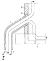
- FIG. 1 shows a box sleeper 1 cast from spheroidal cast iron.
- the Inlet openings 4a, 4b, 4c, 4d are each about 60 ° to the two end faces 6a, 6b inclined (cf. FIGS. 2 and 3). This makes it possible for the Cable protection tube 5 in a relatively soft curve in the entrance opening 4a can be inserted and outside the entrance opening 4a in a small distance runs parallel to the longitudinal wall 3a of the box sleeper 1 (see FIG. 3).
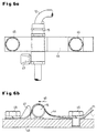
- the in Exemplary embodiment input openings 4b, 4c, 4d are by means of a Cover 7 protected against the ingress of gravel, water and dirt.
- the closure cover 7 is formed on its rear side 8 with two spring clips 9a, 9b, which, after the closure cover 7 has been pressed into the inlet openings 4b, 4c, 4d spread apart and apply non-positively to the opening walls 10a, 10b, whereby the lid 7 is held firmly in the inlet openings 4b, 4c, 4d (cf. Figures 4a, 4b).
- the closure cover 7 has two fixing pins 11a, 11b, the one axial Displacement of the closure cover 7 in the inlet openings 4b, 4c, 4d prevent.
- FIG. 1 two heating rod supply cables 12, 13 led.
- the feed cable 12 becomes the one facing the input opening 4a Heating rod 14 fed directly and connected to the heating rod head 15, while the supply cable 13 by a further threshold floor-side associated with it Cable protection tube 16 up to the heating rod 17 removed from the input opening 4a is passed through where it is connected to the heating rod head 18 there (see Figure 2).
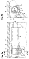
- the cable protection tube 16 lies on paired base webs 19 on.
- the base webs 19 are in the range of the right angle between the Longitudinal wall 3a cast to the box sleeper floor 20.
- a molded opening 21 is formed.
- the web of the sleeper base 20 is the lower bracket 23 of a clamping spring 24 fixed.
- the upper bracket 25 of the clamping spring 24 places the cable protection tube 16 firmly against the base webs 19.
- the spread of the top Clamping bracket 25 - when pressing the cable protection tube 16 between the Base webs 19 and the clamping springs 24 - is by one on the sleeper floor 20 cast fin 26 limited.
- Cable protection tube 16 associated end stops 27 and 28 are Cable protection tube 16 associated end stops 27 and 28 (see. Fig. 1 and 2).
- the heating rods 14, 17 shown in Fig. 1 lie on one in the longitudinal axis the box sleeper 1 extending on the box sleeper floor 20 Spacer bar 29 on (see FIG. 5b).
- the heating rods 14, 17 are three each S-shaped tension springs 30 assigned.
- the tension springs 30 are on base-like Elevations 31 of the box sleeper floor 20 arranged and a lower U-shaped brackets 32 on one each in a sleeper floor 20 Provided opening 33 protruding web 34 of the sleeper floor 20 and the increase 31 fixed.
- the upper tensioning bracket 35 of the S-shaped tensioning spring 30 overlap the heating rods 14, 17 and place them over one in the upper one Clamping bracket 35 formed complementary recess 36 against movement the spacer bar 29.
- the heads 15, 18 of the heating rods 14, 17 are located for reasons of corrosion technology as well as the heating rods 14, 17 even across on the sleeper floor 20 cast-on baseboards 43.
- the heating rod heads 15, 18 are via a spring clip 44 screwed to the skirting 43 on the Skirting board 43 set. So that the heating rod heads 15, 18 when screwing the spring clip 44 by means of the screws 45 and the accompanying Do not push clamps away in the direction of arrow 46, stops 47 are assigned to them.
- the resilient screw connection of the heating element heads 15, 18 ensures - if one is not more intact insulation - safe grounding of the heating element heads 15, 18 (cf. Fig. 1).
- grounding cable For fastening the earth cable, e.g. by means of a Screw / nut combination, is in the longitudinal walls 3a, 3b next to each A bore 48 is provided in the inlet openings 4a, 4b, 4c, 4d (cf. FIGS. 1 and 2).
- Openings 33 as well as those in the middle of the sleeper floor 20 next to the Heating rods 14, 17 introduced openings 49 serve as a water drain.
Landscapes
- Engineering & Computer Science (AREA)
- Mechanical Engineering (AREA)
- Architecture (AREA)
- Civil Engineering (AREA)
- Structural Engineering (AREA)
- Railway Tracks (AREA)
- Resistance Heating (AREA)
- Control And Other Processes For Unpacking Of Materials (AREA)
- Cookers (AREA)
- Devices For Warming Or Keeping Food Or Tableware Hot (AREA)
- Vertical, Hearth, Or Arc Furnaces (AREA)
Claims (8)
- Traverses à caisson (1) à structure fermée pour des dispositifs d'aiguillage, dans lesquelles sont disposées des cartouches de chauffage (14, 17) électriques, caractérisées en ce que les traverses à caisson (1) sont exécutées avec au moins une ouverture d'introduction (4a, 4b, 4c, 4d) pour des lignes d'alimentation (12, 13) des cartouches de chauffage, de telle manière qu'à travers cette ouverture, une ligne d'alimentation (12) des deux lignes d'alimentation (12, 13), guidées dans un tube de protection de câbles commun (5), alimente directement une tête (15) de la cartouche de chauffage (14) face à l'ouverture d'introduction et que l'autre ligne d'alimentation (13) des cartouches de chauffage, guidée à travers un autre tube de protection de câble (16), peut être raccordée à la tête (18) de la cartouche de chauffage (17) éloignée de l'ouverture d'introduction, les têtes (15, 18) des cartouches de chauffage étant fixées sur le fond (20) des traverses à caisson.
- Traverse à caisson selon la revendication 1, caractérisée en ce qu'on a exécuté des ouvertures d'introduction (4a, 4b, 4c, 4d) aux quatre extrémités (2a, 2b, 2c, 2d) des côtés longitudinaux (3a, 3b) de la traverse à caisson.
- Traverse à caisson selon la revendication 1 à 2, caractérisée par un tube de protection de câbles (16) disposé à l'intérieur de la traverse à caisson (1).
- Traverse à caisson selon la revendication 3, caractérisée en ce que le tube de protection de câble (16) est placé sur une barre à socle (19) et est maintenu à l'aide de ressorts de friction (24).
- Traverse à caisson selon une quelconque des revendications 1 à 5, caractérisée en ce que les cartouches de chauffage (14, 17) sont disposées sur un cadre d'écartement (29) et bloquées à l'aide de ressorts de tension (30).
- Traverse à caisson selon une quelconque des revendications 1 à 5, caractérisée en ce que les lignes d'alimentation (12, 13) des cartouches de chauffage, avec les têtes (15, 18) des cartouches de chauffage, sont placées sur un cadre à socle (43) et sont chaque fois fixées avec un étrier à ressort (44).
- Traverse à caisson selon une quelconque des revendications 1 à 6, caractérisée en ce que le fond (20) de la traverse à caisson est exécuté sous forme d'une goulotte et est équipé d'au moins une ouverture d'évacuation d'eau (49).
- Traverse à caisson selon une quelconque des revendications 1 à 7, caractérisée en ce que les cartouches de chauffage (14, 17) et les têtes (15, 18) des cartouches de chauffage présentent des butées latérales et que le tube de protection de câble (16) présente des butées d'extrémité (27, 28).
Applications Claiming Priority (3)
| Application Number | Priority Date | Filing Date | Title |
|---|---|---|---|
| DE19623312 | 1996-06-11 | ||
| DE19623312 | 1996-06-11 | ||
| PCT/EP1997/003004 WO1997047814A1 (fr) | 1996-06-11 | 1997-06-10 | Systeme de chauffage pour traverses a caisson |
Publications (2)
| Publication Number | Publication Date |
|---|---|
| EP0904460A1 EP0904460A1 (fr) | 1999-03-31 |
| EP0904460B1 true EP0904460B1 (fr) | 2000-03-01 |
Family
ID=7796656
Family Applications (1)
| Application Number | Title | Priority Date | Filing Date |
|---|---|---|---|
| EP97925990A Expired - Lifetime EP0904460B1 (fr) | 1996-06-11 | 1997-06-10 | Systeme de chauffage pour traverses a caisson |
Country Status (5)
| Country | Link |
|---|---|
| EP (1) | EP0904460B1 (fr) |
| AT (1) | ATE190099T1 (fr) |
| AU (1) | AU3094497A (fr) |
| DE (1) | DE59701184D1 (fr) |
| WO (1) | WO1997047814A1 (fr) |
Cited By (1)
| Publication number | Priority date | Publication date | Assignee | Title |
|---|---|---|---|---|
| DE102005021636A1 (de) * | 2005-05-06 | 2006-11-16 | SCHWIHAG GESELLSCHAFT FüR EISENBAHNOBERBAU MBH | Eisenbahnschwelle, insbesondere Hohlschwelle |
Families Citing this family (1)
| Publication number | Priority date | Publication date | Assignee | Title |
|---|---|---|---|---|
| AT502480B1 (de) * | 2006-02-13 | 2007-04-15 | Richard Pfanzelter | Trogschwellenheizung für stahltrogschwelle |
Family Cites Families (3)
| Publication number | Priority date | Publication date | Assignee | Title |
|---|---|---|---|---|
| US2704517A (en) * | 1951-08-08 | 1955-03-22 | Gracia Manuel De | Railroad track with rail de-icing means |
| US4391425A (en) * | 1978-03-20 | 1983-07-05 | Keep Jr Henry | Railroad switch heater |
| DE4315200C2 (de) * | 1993-05-07 | 2003-04-30 | Schwihag Gmbh | Querschwelle mit Verstellvorrichtung für Weichenzungen |
-
1997
- 1997-06-10 EP EP97925990A patent/EP0904460B1/fr not_active Expired - Lifetime
- 1997-06-10 AU AU30944/97A patent/AU3094497A/en not_active Abandoned
- 1997-06-10 DE DE59701184T patent/DE59701184D1/de not_active Expired - Fee Related
- 1997-06-10 WO PCT/EP1997/003004 patent/WO1997047814A1/fr not_active Ceased
- 1997-06-10 AT AT97925990T patent/ATE190099T1/de not_active IP Right Cessation
Cited By (1)
| Publication number | Priority date | Publication date | Assignee | Title |
|---|---|---|---|---|
| DE102005021636A1 (de) * | 2005-05-06 | 2006-11-16 | SCHWIHAG GESELLSCHAFT FüR EISENBAHNOBERBAU MBH | Eisenbahnschwelle, insbesondere Hohlschwelle |
Also Published As
| Publication number | Publication date |
|---|---|
| WO1997047814A1 (fr) | 1997-12-18 |
| ATE190099T1 (de) | 2000-03-15 |
| DE59701184D1 (de) | 2000-04-06 |
| AU3094497A (en) | 1998-01-07 |
| EP0904460A1 (fr) | 1999-03-31 |
Similar Documents
| Publication | Publication Date | Title |
|---|---|---|
| EP2069577B1 (fr) | Système de retenue de véhicules | |
| LU88479A1 (de) | Querschwellen f}r Eisenbahn-Gleisanlagen | |
| DE3720381A1 (de) | Vorrichtung zur befestigung von eisenbahnschienen auf fester fahrbahn | |
| EP0726359B1 (fr) | Voie de chemin de fer utilisée plus particulièrement sur terrain gazonné | |
| DE19651017C1 (de) | Aufgeständerter Kabelkanal | |
| DE102007048304B3 (de) | Fahrzeugrückhaltesystem | |
| DE3447836C2 (fr) | ||
| EP0904460B1 (fr) | Systeme de chauffage pour traverses a caisson | |
| DE202010008581U1 (de) | Weiche mit Weichenantrieb | |
| DE102007048303A1 (de) | Fahrzeugrückhaltesystem | |
| DE19836507B4 (de) | Mehrphasige Stromsammelschiene | |
| WO2021047960A1 (fr) | Dispositif de drainage | |
| EP2262953B1 (fr) | Système de retenue pour véhicule | |
| EP1518026A1 (fr) | Dispositif a contre-rail | |
| DE19806223A1 (de) | Gleis mit zwischen den Schienen angeordneten Gleisentwässerungskästen | |
| EP4174249A1 (fr) | Panneau creux composite et ensemble comprenant un certain nombre de panneaux creux composites | |
| DE102017118131A1 (de) | Mittel und Verfahren zum Stoss-Schweissen von Schienenbrüchen | |
| DE3106262C1 (de) | Stahlschwelle für den Eisenbahnoberbau | |
| DE102009030535B4 (de) | Mehrteilige Schienenkammerfülleinrichtung | |
| DE3007947A1 (de) | Dachabdeckung | |
| CH684721A5 (de) | Modulare Stromschienenvorrichtung. | |
| DE202010008526U1 (de) | Betonschwelle | |
| DE202019106103U1 (de) | Drainageeinrichtung für Tür- oder Fensterelemente | |
| DE19801584A1 (de) | Rillenschiene | |
| EP0610309B1 (fr) | Dispositif pour la collecte de matieres nocives liquides et/ou granuleuses au voisinage des rails de vehicules sur rail |
Legal Events
| Date | Code | Title | Description |
|---|---|---|---|
| PUAI | Public reference made under article 153(3) epc to a published international application that has entered the european phase |
Free format text: ORIGINAL CODE: 0009012 |
|
| 17P | Request for examination filed |
Effective date: 19981209 |
|
| AK | Designated contracting states |
Kind code of ref document: A1 Designated state(s): AT CH DE LI |
|
| GRAG | Despatch of communication of intention to grant |
Free format text: ORIGINAL CODE: EPIDOS AGRA |
|
| 17Q | First examination report despatched |
Effective date: 19990628 |
|
| GRAG | Despatch of communication of intention to grant |
Free format text: ORIGINAL CODE: EPIDOS AGRA |
|
| GRAH | Despatch of communication of intention to grant a patent |
Free format text: ORIGINAL CODE: EPIDOS IGRA |
|
| GRAH | Despatch of communication of intention to grant a patent |
Free format text: ORIGINAL CODE: EPIDOS IGRA |
|
| GRAA | (expected) grant |
Free format text: ORIGINAL CODE: 0009210 |
|
| AK | Designated contracting states |
Kind code of ref document: B1 Designated state(s): AT CH DE LI |
|
| REF | Corresponds to: |
Ref document number: 190099 Country of ref document: AT Date of ref document: 20000315 Kind code of ref document: T |
|
| REG | Reference to a national code |
Ref country code: CH Ref legal event code: EP |
|
| REF | Corresponds to: |
Ref document number: 59701184 Country of ref document: DE Date of ref document: 20000406 |
|
| REG | Reference to a national code |
Ref country code: CH Ref legal event code: NV Representative=s name: SCHMAUDER & PARTNER AG PATENTANWALTSBUERO |
|
| EN | Fr: translation not filed | ||
| PLBE | No opposition filed within time limit |
Free format text: ORIGINAL CODE: 0009261 |
|
| STAA | Information on the status of an ep patent application or granted ep patent |
Free format text: STATUS: NO OPPOSITION FILED WITHIN TIME LIMIT |
|
| 26N | No opposition filed | ||
| PGFP | Annual fee paid to national office [announced via postgrant information from national office to epo] |
Ref country code: CH Payment date: 20080613 Year of fee payment: 12 |
|
| PGFP | Annual fee paid to national office [announced via postgrant information from national office to epo] |
Ref country code: AT Payment date: 20080616 Year of fee payment: 12 |
|
| PGFP | Annual fee paid to national office [announced via postgrant information from national office to epo] |
Ref country code: DE Payment date: 20080620 Year of fee payment: 12 |
|
| REG | Reference to a national code |
Ref country code: CH Ref legal event code: PCAR Free format text: SCHMAUDER & PARTNER AG PATENT- UND MARKENANWAELTE VSP;ZWAENGIWEG 7;8038 ZUERICH (CH) |
|
| REG | Reference to a national code |
Ref country code: CH Ref legal event code: PL |
|
| PG25 | Lapsed in a contracting state [announced via postgrant information from national office to epo] |
Ref country code: LI Free format text: LAPSE BECAUSE OF NON-PAYMENT OF DUE FEES Effective date: 20090630 Ref country code: CH Free format text: LAPSE BECAUSE OF NON-PAYMENT OF DUE FEES Effective date: 20090630 |
|
| PG25 | Lapsed in a contracting state [announced via postgrant information from national office to epo] |
Ref country code: DE Free format text: LAPSE BECAUSE OF NON-PAYMENT OF DUE FEES Effective date: 20100101 Ref country code: AT Free format text: LAPSE BECAUSE OF NON-PAYMENT OF DUE FEES Effective date: 20090610 |