EP0904460B1 - Heating system for box-type sleepers - Google Patents
Heating system for box-type sleepers Download PDFInfo
- Publication number
- EP0904460B1 EP0904460B1 EP97925990A EP97925990A EP0904460B1 EP 0904460 B1 EP0904460 B1 EP 0904460B1 EP 97925990 A EP97925990 A EP 97925990A EP 97925990 A EP97925990 A EP 97925990A EP 0904460 B1 EP0904460 B1 EP 0904460B1
- Authority
- EP
- European Patent Office
- Prior art keywords
- box
- heating rod
- heating
- protection tube
- box sleeper
- Prior art date
- Legal status (The legal status is an assumption and is not a legal conclusion. Google has not performed a legal analysis and makes no representation as to the accuracy of the status listed.)
- Expired - Lifetime
Links
Images


Classifications
-
- E—FIXED CONSTRUCTIONS
- E01—CONSTRUCTION OF ROADS, RAILWAYS, OR BRIDGES
- E01B—PERMANENT WAY; PERMANENT-WAY TOOLS; MACHINES FOR MAKING RAILWAYS OF ALL KINDS
- E01B7/00—Switches; Crossings
- E01B7/24—Heating of switches
Definitions
- the invention relates to box sleepers in a closed construction for switch devices, in which electrical heating elements are arranged, as by DE-A-43 15 200 known.
- the previously used box sleepers - which for better darning by means Switch tamping machines and improved settlement behavior are the same Box cross-sections such as wooden or concrete sleepers have - to the Reduce production costs, from relatively thin folded sheets to U-profiles formed, on the two flanges of which the upper chords are welded. To the cost to keep consciously low, the entire cross section of the box sleeper is disregarded after the welding process to glow with low stress, which is a brings increased cracking and corrosion.
- the heat transfer is the Heating rods on the entire box threshold very bad because the heating rod with only two fastening clamps on the - bulged by the ballast and thereby wavy - floor plate is mounted.
- the heating element cross section is often in a water accumulation area so that premature corrosion and thereby a possible defect, e.g. a short circuit is preprogrammed.
- the invention is based, with a generic box threshold the task the arrangement or accommodation of the box sleeper heating improve, in particular the availability of the switch and operational safety increase.
- the box threshold is formed at least with an inlet opening for heating element feed lines in such a way that the heating rod can be replaced through this opening.
- the entrance opening is located preferably in one of the two longitudinal walls of the box sleeper and is 60 ° in Inclined towards the front wall of the box sleeper. This allows the Heating rod feed lines - there are usually two heating rods for one box threshold - with a relatively small amount of buckling together through the entrance opening in the Introduce box threshold.
- the entrance openings are chosen so large that one of the two supply cables Receiving angled cable protection tube, which is preferably made of plastic exists, can be inserted inside the box threshold. With that they are Supply cable on the one hand in the area of the entrance opening and on the other hand outside the box sleeper effectively protected against damage in the area of the ballast.
- a is in the interior of the box threshold Cable protection tube arranged.
- a supply cable becomes that of the selected one Inlet opening on the closest heating element is fed directly while the other supply cables through the inner protective tube to the from the Heating rod removed from the inlet opening.
- the cable protection tube Base bars rests and is held by means of clamping springs.
- the plinths are in the right-angled transition area between the longitudinal wall and the floor of the Box threshold arranged. Are over the entire length of the box threshold
- Tension springs arranged between two base bars, which are in the sleeper floor trained openings protrude and on a web delimiting the opening of the sleeper floor are fixed.
- the cable protection tube is through easy to push in between the clamping spring and base bars locked, on the other hand the clamped cable protection tube lies on the baseboards, so that any water on the sleeper floor is not in the Protective tube can penetrate.
- end stops are advantageously assigned to the cable protection tube, between which the cable protection tube is embedded immovably axially; thereby a pinching of the cable between the front sides of the box threshold and the Cable protection tube effectively prevented.
- a preferred embodiment of the invention provides that the heating elements on a Spacer bar arranged and locked there by means of tension springs.
- the spacer bar is in the longitudinal axis of the box sleeper on the box sleeper floor arranged; on it lie the two arranged one after the other on one level Heating rods on.
- the preferably S-shaped tension springs are each on a raised base.
- the upper clamps overlap the heating rods and fix them on the spacer bar.
- the lower clamp of the Tension spring protrudes into a turnstile which is also formed in the sleeper floor Opening and is on a web of the raised base and delimiting the opening of the sleeper floor fixed securely.
- the heating rods are several on the Bottom rail assigned stops arranged.
- Another embodiment of the invention provides that the heating rod heads on a Place the skirting board and fasten it with a spring clip.
- the Skirting board is between the vertical longitudinal walls of the box threshold on the Box sleeper floor arranged.
- the heating rod heads are with an overlapping double-lobed clamp or one made of spring steel Band resiliently screwed against the skirting board. Thanks to the resilient screw connection the heating rod heads will be safely grounded if they are no longer intact Heating rod insulation guaranteed.
- the heating element heads are also on the side Stop assigned to when screwing the double-lobed clamp or Spring band to prevent the heating rod head from slipping.
- the heating elements or the heating element heads on the Box sleeper floor and the associated full-surface support results on the one hand, good heat transfer to the floor area of the box sleeper.
- the heating elements used up to now with an individual heating output of Exchange 2x450W for heating elements with a single heating output of 200-300W which has a very big economic advantage.
- the Heating elements are not - as is usual with known arrangements - in the water collection area the box threshold, which effectively corrodes the heating rods is prevented.
- the sleeper floor is gutter-like trained and provided with at least one water drain opening.
- Under Channel-like formation of the floor are both in the longitudinal and in the transverse direction Floor surfaces inclined towards the water drainage opening that understand the water direct the process to the lowest point.
- FIG. 1 shows a box sleeper 1 cast from spheroidal cast iron.
- the Inlet openings 4a, 4b, 4c, 4d are each about 60 ° to the two end faces 6a, 6b inclined (cf. FIGS. 2 and 3). This makes it possible for the Cable protection tube 5 in a relatively soft curve in the entrance opening 4a can be inserted and outside the entrance opening 4a in a small distance runs parallel to the longitudinal wall 3a of the box sleeper 1 (see FIG. 3).
- the in Exemplary embodiment input openings 4b, 4c, 4d are by means of a Cover 7 protected against the ingress of gravel, water and dirt.
- the closure cover 7 is formed on its rear side 8 with two spring clips 9a, 9b, which, after the closure cover 7 has been pressed into the inlet openings 4b, 4c, 4d spread apart and apply non-positively to the opening walls 10a, 10b, whereby the lid 7 is held firmly in the inlet openings 4b, 4c, 4d (cf. Figures 4a, 4b).
- the closure cover 7 has two fixing pins 11a, 11b, the one axial Displacement of the closure cover 7 in the inlet openings 4b, 4c, 4d prevent.
- FIG. 1 two heating rod supply cables 12, 13 led.
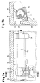
- the feed cable 12 becomes the one facing the input opening 4a Heating rod 14 fed directly and connected to the heating rod head 15, while the supply cable 13 by a further threshold floor-side associated with it Cable protection tube 16 up to the heating rod 17 removed from the input opening 4a is passed through where it is connected to the heating rod head 18 there (see Figure 2).
- the cable protection tube 16 lies on paired base webs 19 on.
- the base webs 19 are in the range of the right angle between the Longitudinal wall 3a cast to the box sleeper floor 20.
- a molded opening 21 is formed.
- the web of the sleeper base 20 is the lower bracket 23 of a clamping spring 24 fixed.
- the upper bracket 25 of the clamping spring 24 places the cable protection tube 16 firmly against the base webs 19.
- the spread of the top Clamping bracket 25 - when pressing the cable protection tube 16 between the Base webs 19 and the clamping springs 24 - is by one on the sleeper floor 20 cast fin 26 limited.
- Cable protection tube 16 associated end stops 27 and 28 are Cable protection tube 16 associated end stops 27 and 28 (see. Fig. 1 and 2).
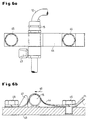
- the heating rods 14, 17 shown in Fig. 1 lie on one in the longitudinal axis the box sleeper 1 extending on the box sleeper floor 20 Spacer bar 29 on (see FIG. 5b).
- the heating rods 14, 17 are three each S-shaped tension springs 30 assigned.
- the tension springs 30 are on base-like Elevations 31 of the box sleeper floor 20 arranged and a lower U-shaped brackets 32 on one each in a sleeper floor 20 Provided opening 33 protruding web 34 of the sleeper floor 20 and the increase 31 fixed.
- the upper tensioning bracket 35 of the S-shaped tensioning spring 30 overlap the heating rods 14, 17 and place them over one in the upper one Clamping bracket 35 formed complementary recess 36 against movement the spacer bar 29.
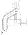
- the heads 15, 18 of the heating rods 14, 17 are located for reasons of corrosion technology as well as the heating rods 14, 17 even across on the sleeper floor 20 cast-on baseboards 43.
- the heating rod heads 15, 18 are via a spring clip 44 screwed to the skirting 43 on the Skirting board 43 set. So that the heating rod heads 15, 18 when screwing the spring clip 44 by means of the screws 45 and the accompanying Do not push clamps away in the direction of arrow 46, stops 47 are assigned to them.
- the resilient screw connection of the heating element heads 15, 18 ensures - if one is not more intact insulation - safe grounding of the heating element heads 15, 18 (cf. Fig. 1).
- grounding cable For fastening the earth cable, e.g. by means of a Screw / nut combination, is in the longitudinal walls 3a, 3b next to each A bore 48 is provided in the inlet openings 4a, 4b, 4c, 4d (cf. FIGS. 1 and 2).
- Openings 33 as well as those in the middle of the sleeper floor 20 next to the Heating rods 14, 17 introduced openings 49 serve as a water drain.
Abstract
Description
Die Erfindung betrifft Kastenschwellen in geschlossener Bauweise für Weicheneinrichtungen, in denen elektrische Heizstäbe angeordnet sind, wie durch die DE-A-43 15 200 bekanntgeworden.The invention relates to box sleepers in a closed construction for switch devices, in which electrical heating elements are arranged, as by DE-A-43 15 200 known.
Zur Aufnahme und Anordnung von kompletten Klammerverschlüssen, Klinkenverschlüssen, vertikalen Klammerverschlüssen sowie Zungenprüfern und Federwippen für bewegliche Zungen und/oder bewegliche Herzstückspitzen werden in den letzten Jahren verstärkt Kasten- oder Trogschwellen eingesetzt. Durch ihren Einsatz ergeben sich vielfältige Vorteile, z.B. ein schmierungs- und wartungsarmes Weichenstellsystem, ein geringerer Unterhaltungsaufwand und die Möglichkeit des automatischen Stopfens der Kastenschwellen, ohne dabei den Schotter zu zerstören. Die Verfügbarkeit der Weichenstellsysteme wird dadurch wesentlich erhöht.For receiving and arranging complete clip locks, latch locks, vertical clamp closures as well as tongue testers and spring rockers for Movable tongues and / or moveable centerpiece tips have been used in recent years increasingly used box or trough sleepers. Through their dedication arise diverse advantages, e.g. a low-lubrication and low-maintenance point setting system less maintenance and the possibility of automatic tamping Box sleepers without destroying the ballast. The availability of the Switch setting systems are significantly increased.
Die bisher eingesetzten Kastenschwellen - welche zum besseren Stopfen mittels Weichenstopfmaschinen sowie eines verbesserten Setzungsverhaltens die gleichen Kastenquerschnitte wie Holz- oder Betonschwellen aufweisen - werden, um die Produktionskosten zu senken, aus relativ dünnen abgekanteten Blechen zu U-Pofilen geformt, auf deren beiden Flanschen die Obergurte angeschweißt werden. Um die Kosten bewußt niedrig zu halten, wird davon abgesehen, den gesamten Kastenschwellenquerschnitt nach dem Schweißvorgang spannungsarm zu glühen, was allerdings eine erhöhte Riß- und Korrosionsbildung mit sich bringt.The previously used box sleepers - which for better darning by means Switch tamping machines and improved settlement behavior are the same Box cross-sections such as wooden or concrete sleepers have - to the Reduce production costs, from relatively thin folded sheets to U-profiles formed, on the two flanges of which the upper chords are welded. To the cost to keep consciously low, the entire cross section of the box sleeper is disregarded after the welding process to glow with low stress, which is a brings increased cracking and corrosion.
Des weiteren stellt sich durch das Abkanten der etwa 10mm starken Kastenschwellenbleche der Nachteil ein, daß die Übergänge vom horizontalen Bodenbereich der Kastenschwelle zu ihren vertikalen Flanschbereichen einen großen Biegeradius aufweisen. Beim Stopfen der Kastenschwellen ist durch die großen Biegeradien kein optimal dichtes Stopfen möglich, da der Schotter nach oben quillt. Diesem Stopfproblem läßt sich mehr oder weniger erfolgreich einerseits durch Handstopfen und andererseits durch über die ganze Länge an den Kastenschwellen-Fußlängskanten angeschweißten Winkeln begegnen.Furthermore, by bending the approximately 10mm thick Box sleepers the disadvantage that the transitions from horizontal Floor area of the box sleeper a large to their vertical flange areas Have a bending radius. When darning the box sleepers is due to the big ones Bending radii cannot be optimally sealed because the ballast swells upwards. This stuffing problem can be more or less successfully managed on the one hand Hand plugs and on the other hand along the entire length of the box sleeper foot edges encounter welded angles.
Um z.B. eine Eisbildung in den meist nach oben offenen Kastenschwellen zu verhindern, werden in diese elektrische Kastenschwellenheizungen - in Form von Heizstäben - eingebaut. Eine vorgeschriebene bzw. definierte Einbauposition für die Heizstäbe gibt es nicht, so daß diese von jeder Einbaufirma oder den Einbautrupps der Staatsbahnen unterschiedlich und meist mit großen Nachteilen behaftet in die Kastenschwellen installiert werden. Zum einen ist die Wärmeübertragung der Heizstäbe auf die gesamte Kastenschwelle sehr schlecht, weil der Heizstab mit nur zwei Befestigungsschellen auf dem - durch den Schotter aufgebeulten und dadurch welligen - Bodenblech montiert ist. Zum anderen liegt der Heizstabquerschnitt oft in einem Wasseransammlungsbereich, so daß eine vorzeitige Korrosion und dadurch ein möglicher Defekt, z.B. ein Kurzschluß, vorprogrammiert ist.To e.g. formation of ice in the box sleepers, which are mostly open at the top prevent in this electrical box threshold heaters - in the form of Heating rods - built-in. A prescribed or defined installation position for the There are no heating elements, so they are available from every installation company or installation team of the state railways different and mostly with major disadvantages in the Box sleepers can be installed. For one, the heat transfer is the Heating rods on the entire box threshold very bad because the heating rod with only two fastening clamps on the - bulged by the ballast and thereby wavy - floor plate is mounted. On the other hand, the heating element cross section is often in a water accumulation area so that premature corrosion and thereby a possible defect, e.g. a short circuit is preprogrammed.
Meist sind im Bodenbereich der Kastenschwellen keine oder nur wenige Wasserablauflöcher vorgesehen, so daß sich auf dem unebenen Boden Wasserpfützen bilden, die bis zur Verdunstung bestehen bleiben und insbesondere in Verbindung mit Schmutz- und Abfallansammlungen in der Kastenschwelle zu einem Wassersumpf führen.Usually there are no or only a few in the floor area of the box sleepers Water drainage holes are provided so that they are on the uneven floor Form puddles of water that remain until evaporation and especially in Connection with dirt and waste accumulations in the box threshold to one Lead water sump.
Weiterhin sind nach dem Einbau eines Spitzenverschlusses die Befestigungsschellen der Verschraubungen für die Heizstäbe oft, nicht mehr lösbar, so daß der Spitzenverschluß teilweise oder ganz demontiert werden muß, bevor man an die Heizstäbe gelangt. Außerdem dauert die Auswechslung eines defekten Heizstabes viel zu lange, was die Verfügbarkeit der Weiche wesentlich reduziert.Furthermore, after the installation of a tip lock, the mounting clamps of the screw connections for the heating elements often, no longer releasable, so that the Tip closure must be partially or completely disassembled before you get to the Heating rods arrives. The replacement of a defective heating element also takes time far too long, which significantly reduces the availability of the switch.
Der Erfindung liegt die Aufgabe zugrunde, bei einer gattungsgemäßen Kastenschwelle die Anordnung bzw. Unterbringung der Kastenschwellenheizung zu verbessern, insbesondere die Verfügbarkeit der Weiche und die Betriebssicherheit zu erhöhen.The invention is based, with a generic box threshold the task the arrangement or accommodation of the box sleeper heating improve, in particular the availability of the switch and operational safety increase.
Diese Aufgabe wird durch die Merkmalskombination des Anspruchs 1 gelöst, wobei die Kastenschwelle mindestens mit einer Eingangsöffnung für Heizstabzuleitungen derart ausgebildet ist, daß durch diese Öffnung der Heizstab auswechselbar ist. Die Eingangsöffnung befindet sich vorzugsweise in einer der beiden Längswände der Kastenschwelle und ist um 60° in Richtung Stirnwand der Kastenschwelle geneigt. Dadurch lassen sich die Heizstabzuleitungen - es sind meist zwei Heizstäbe für eine Kastenschwelle vorgesehen - mit einem relativ geringen Knickmaß gemeinsam durch die Eingangsöffnung in die Kastenschwelle einführen.This object is achieved by the combination of features of claim 1, the box threshold is formed at least with an inlet opening for heating element feed lines in such a way that the heating rod can be replaced through this opening. The entrance opening is located preferably in one of the two longitudinal walls of the box sleeper and is 60 ° in Inclined towards the front wall of the box sleeper. This allows the Heating rod feed lines - there are usually two heating rods for one box threshold - with a relatively small amount of buckling together through the entrance opening in the Introduce box threshold.
Vorzugsweise ist bei der Erfindung vorgesehen, daß an allen vier Enden der Kastenschwellen-Längsseiten Eingangsöffnungen ausgebildet sind. So ist es möglich, je nachdem auf welcher Seite und in welchem Abstand von der Kastenschwelle ein Elektro-Anschlußkasten angeordnet ist, die Zuleitungskabel auf dem kürzesten Weg und gegebenenfalls ohne sie in der Erde verlegen zu müssen, eine der vier Eingangsöffnungen zuzuführen. In die nicht benötigten Eingangsöffnungen wird ein Lochverschlußdeckel eingedrückt, der durch eine an ihm angeordnete Bügelfeder in der jeweiligen Eingangsöffnung festgehalten wird, so daß beim Stopfen kein Schotter in die Kastenschwelle gelangen kann.It is preferably provided in the invention that at all four ends Box threshold longitudinal sides of the inlet openings are formed. So it is possible, ever on which side and at what distance from the box threshold Electrical connection box is arranged, the supply cable on the shortest route and if necessary, without having to lay them in the ground, one of the four Feed entry openings. A is inserted into the unused entry openings Punch closure lid pressed in by a bow spring arranged on it in the respective entrance opening is held so that no ballast in the plug Box threshold can reach.
Die Eingangsöffnungen sind so groß gewählt, daß ein beide Zuleitungskabel aufnehmendes abgewinkeltes Kabelschutzrohr, welches vorzugsweise aus Kunststoff besteht, ins Innere der Kastenschwelle eingeführt werden kann. Damit sind die Zuleitungskabel einerseits im Bereich der Eingangsöffnung und andererseits außerhalb der Kastenschwelle im Bereich des Schotters wirksam gegen Beschädigungen geschützt.The entrance openings are chosen so large that one of the two supply cables Receiving angled cable protection tube, which is preferably made of plastic exists, can be inserted inside the box threshold. With that they are Supply cable on the one hand in the area of the entrance opening and on the other hand outside the box sleeper effectively protected against damage in the area of the ballast.
Nach einer Ausgestaltung der Erfindung ist im Inneren der Kastenschwelle ein Kabelschutzrohr angeordnet. Ein Zuleitungskabel wird dem der gewählten Eingangsöffnung am nächsten liegenden Heizstab direkt zugeführt, während das andere Zuleitungskabel durch das innenliegende Schutzrohr zu dem von der Eingangsöffnung entfernten Heizstab gelangt.According to one embodiment of the invention, a is in the interior of the box threshold Cable protection tube arranged. A supply cable becomes that of the selected one Inlet opening on the closest heating element is fed directly while the other supply cables through the inner protective tube to the from the Heating rod removed from the inlet opening.
Eine weitere Ausgestaltung der Erfindung sieht vor, daß das Kabelschutzrohr auf Sockelstegen aufliegt und mittels Klemmfedern gehalten wird. Die Sockelstege sind im rechtwinkligen Übergangsbereich zwischen Längswand und Boden der Kastenschwelle angeordnet. Über die gesamte Länge der Kastenschwelle sind jeweils zwischen zwei Sockelstegen Spannfedern angeordnet, die in im Kastenschwellenboden ausgebildete Öffnungen ragen und an einem die Öffnung begrenzenden Steg des Kastenschwellenbodens fixiert sind. Einerseits ist das Kabelschutzrohr durch einfaches Eindrücken zwischen Klemmfeder und Sockelstegen auszugssicher arretiert, andererseits liegt das geklemmte Kabelschutzrohr auf den Sockelleisten auf, so daß eventuell auf dem Kastenschwellenboden stehendes Wasser nicht in das Schutzrohr eindringen kann.Another embodiment of the invention provides that the cable protection tube Base bars rests and is held by means of clamping springs. The plinths are in the right-angled transition area between the longitudinal wall and the floor of the Box threshold arranged. Are over the entire length of the box threshold Tension springs arranged between two base bars, which are in the sleeper floor trained openings protrude and on a web delimiting the opening of the sleeper floor are fixed. On the one hand, the cable protection tube is through easy to push in between the clamping spring and base bars locked, on the other hand the clamped cable protection tube lies on the baseboards, so that any water on the sleeper floor is not in the Protective tube can penetrate.
Des weiteren sind dem Kabelschutzrohr vorteilhaft Endanschläge zugeordnet, zwischen denen das Kabelschutzrohr axial unbeweglich eingebettet ist; dadurch wird ein Einquetschen des Kabels zwischen den Stirnseiten der Kastenschwelle und dem Kabelschutzrohr wirksam verhindert.Furthermore, end stops are advantageously assigned to the cable protection tube, between which the cable protection tube is embedded immovably axially; thereby a pinching of the cable between the front sides of the box threshold and the Cable protection tube effectively prevented.
Eine bevorzugte Ausgestaltung der Erfindung sieht vor, daß die Heizstäbe auf einer Abstandsleiste angeordnet und dort mittels Spannfedern arretiert sind. Die Abstandsleiste ist in der Längsachse der Kastenschwelle auf dem Kastenschwellenboden angeordnet; auf ihr liegen die beiden auf einer Ebene hintereinander angeordneten Heizstäbe auf. Die vorzugsweise S-förmig ausgebildeten Spannfedern liegen jeweils auf einem erhöhten Sockel auf. Ihre oberen Spannbügel übergreifen die Heizstäbe und legen diese kraftschlüssig auf der Abstandsleiste fest. Der untere Spannbügel der Spannfeder ragt in eine auch wiederum im Kastenschwellenboden ausgebildete Öffnung und ist an einem die Öffnung begrenzenden Steg des erhöhten Sockels und des Kastenschwellenbodens bewegungssicher fixiert. A preferred embodiment of the invention provides that the heating elements on a Spacer bar arranged and locked there by means of tension springs. The spacer bar is in the longitudinal axis of the box sleeper on the box sleeper floor arranged; on it lie the two arranged one after the other on one level Heating rods on. The preferably S-shaped tension springs are each on a raised base. The upper clamps overlap the heating rods and fix them on the spacer bar. The lower clamp of the Tension spring protrudes into a turnstile which is also formed in the sleeper floor Opening and is on a web of the raised base and delimiting the opening of the sleeper floor fixed securely.
Damit die Heizstäbe beim seitlichen Einschieben in die vormontierten Spannfedern zum einen nicht über die Abstandsleiste hinausgeschoben werden können und zum anderen in axialer Richtung fluchten, sind den Heizstäben mehrere auf der Bodenleiste angeordenete Anschläge zugeordent.So that the heating elements when inserted laterally into the pre-assembled tension springs on the one hand cannot be pushed over the spacer bar and on the other others are aligned in the axial direction, the heating rods are several on the Bottom rail assigned stops arranged.
Eine weitere Ausgestaltung der Erfindung sieht vor, daß die Heizstabköpfe auf einer Sockelleiste aufliegen und jeweils mit einer Federschelle befestigt sind. Die Sockelleiste ist zwischen den senkrechten Längswänden der Kastenschwelle auf dem Kastenschwellenboden angeordnet. Die Heizstabköpfe werden mit einer sie übergreifenden doppellappigen Schelle respektive einem aus Federstahl hergestellten Band federnd gegen die Sockelleiste verschraubt. Durch die federnde Verschraubung der Heizstabköpfe wird eine sichere Erdung, bei nicht mehr intakten Heizstab-Isolierungen, gewährleistet. Auch den Heizstabköpfen ist ein seitlicher Anschlag zugeordnet, um beim Verschrauben der doppellappigen Schelle bzw. des Federbandes ein Verrutschen des Heizstabkopfes zu verhindern.Another embodiment of the invention provides that the heating rod heads on a Place the skirting board and fasten it with a spring clip. The Skirting board is between the vertical longitudinal walls of the box threshold on the Box sleeper floor arranged. The heating rod heads are with an overlapping double-lobed clamp or one made of spring steel Band resiliently screwed against the skirting board. Thanks to the resilient screw connection the heating rod heads will be safely grounded if they are no longer intact Heating rod insulation guaranteed. The heating element heads are also on the side Stop assigned to when screwing the double-lobed clamp or Spring band to prevent the heating rod head from slipping.
Durch die erhöhte Anordnung der Heizstäbe bzw. der Heizstabköpfe auf dem Kastenschwellenboden und die damit verbundene ganzflächige Auflage ergibt sich einerseits eine gute Wärmeübertragung auf den Bodenbereich der Kastenschwelle. Andererseits ist es möglich, in Verbindung mit der nach oben geschlossenen Kastenschwelle, die bisher eingesetzten Heizstäbe mit einer Einzelheizleistung von 2x450W gegen Heizstäbe mit einer Einzelheizleistung von 200-300W auszutauschen, was einen sehr großen wirtschaftlichen Vorteil mit sich bringt. Des weiteren liegen die Heizstäbe nicht - wie bei bekannten Anordnungen üblich - im Wasseransammlungsbereich der Kastenschwelle, wodurch eine Korrosion der Heizstäbe wirkungsvoll verhindert wird.Due to the increased arrangement of the heating elements or the heating element heads on the Box sleeper floor and the associated full-surface support results on the one hand, good heat transfer to the floor area of the box sleeper. On the other hand, it is possible in connection with the closed up Box threshold, the heating elements used up to now with an individual heating output of Exchange 2x450W for heating elements with a single heating output of 200-300W, which has a very big economic advantage. Furthermore, the Heating elements are not - as is usual with known arrangements - in the water collection area the box threshold, which effectively corrodes the heating rods is prevented.
Um eine Wasseransammlung in den Kastenschwellen von vornherein zu verhindern, ist nach einer Ausgestaltung der Erfindung der Kastenschwellenboden rinnenartig ausgebildet und mit mindestens einer Wasserablauföffnung versehen. Unter rinnenartiger Ausbildung des Bodens sind sowohl in Längs- als auch in Querrichtung zur Wasserablauföffnung hin geneigte Bodenflächen zu verstehen, die das Wasser gezielt im tiefsten Punkt dem Ablauf zuführen. Vorzugsweise sind mehrere Wasserablauföffnungen vorgesehen, nämlich zum einen werden die in der Längsachse des Kastenschwellenbodens für die Spannfedern der Heizstäbe ohnehin vorgesehenen Öffnungen ausgenutzt und zum anderen in der Mitte des Kastenschwellenbodens zusätzlich Ablauföffnungen ausgebildet. Dadurch ist es möglich, daß in der Kastenschwelle auftretendes Kondenswasser oder Regenwasser vollständig abfließen kann und sich bei geneigten Kastenschwellen, z.B. einer überhöhten Weichenlage, im Inneren kein Wasser ansammeln kann. Um den Ablaufeffekt noch zu steigern, lassen sich die Ränder der Wasserablauföffnungen anschrägen.To prevent water accumulation in the box sleepers from the outset, According to one embodiment of the invention, the sleeper floor is gutter-like trained and provided with at least one water drain opening. Under Channel-like formation of the floor are both in the longitudinal and in the transverse direction Floor surfaces inclined towards the water drainage opening that understand the water direct the process to the lowest point. Preferably there are several water drainage openings provided, namely on the one hand in the longitudinal axis of the Box sleeper floor provided for the tension springs of the heating elements anyway Openings exploited and the other in the middle of the sleeper floor drain openings are also formed. This makes it possible that in the Drain any condensation water or rainwater that may occur can and with inclined box sleepers, e.g. an excessive turnout, in No water can accumulate inside. To increase the drainage effect, leave the edges of the water drainage openings bevel.
Weitere Einzelheiten und Vorteile der Erfindung ergeben sich aus den Ansprüchen und der nachfolgenden Beschreibung, in der in den Zeichnungen dargestellte Ausführungsbeispiele der Erfindung näher erläutert sind. Es zeigen:
- Figur 1
- eine Kastenschwelle mit darin angeordneten Heizstäben, in der Draufsicht dargestellt;
- Figur 2
- die Kastenschwelle gemäß Fig. 1 mit zwei Eingangsöffnungen für Heizstabzuleitungen, von der Seite her gesehen und im Längsschnitt dargestellt;
- Figur 3
- als Einzelheit eine Eingangsöffnung der Kastenschwelle gemäß Fig. 2 mit einem Kabelschutzrohr, in der Draufsicht und im Schnitt dargestellt;
Figur 4a- als Einzelheit eine Eingangsöffnung der Kastenschwelle mit einem Verschlußdeckel, in der Draufsicht und im Teillängsschnitt dargestellt;
Figur 4b- einen Schnitt entlang der Linie IV-IV von Fig. 4a;
- Figur 5a
- als Einzelheit eine Teilansicht eines Heizstabes gemäß Fig. 1, in der Draufsicht und im Längsschnitt dargestellt;
- Figur 5b
- einen Schnitt entlang der Linie V-V von Fig. 5a;
- Fig. 6a,6b
- als Einzelheit die Befestigung eines Heizstabkopfes, in der Draufsicht (Fig. 6a) und in der Vorderansicht (Fig. 6b) dargestellt;
- Figur 7a
- als Einzelheit eine Teilansicht eines in der Kastenschwelle gemäß Fig. 2 angeordneten Kabelschutzrohres, in der Draufsicht und im Längsschnitt dargestellt; und
- Figur 7b
- einen Schnitt entlang der Linie VII - VII von Fig. 7a.
- Figure 1
- a box threshold with heating elements arranged therein, shown in plan view;
- Figure 2
- the box threshold according to Figure 1 with two inlet openings for heating rod leads, seen from the side and shown in longitudinal section.
- Figure 3
- as a detail, an entrance opening of the box sleeper according to FIG 2 with a cable protection tube, shown in plan view and in section.
- Figure 4a
- shown as a detail an entrance opening of the box sleeper with a closure cover, in plan view and in partial longitudinal section;
- Figure 4b
- a section along the line IV-IV of Fig. 4a;
- Figure 5a
- as a detail, a partial view of a heating element according to FIG 1, shown in plan view and in longitudinal section.
- Figure 5b
- a section along the line VV of Fig. 5a;
- 6a, 6b
- as a detail, the attachment of a heating rod head, shown in plan view (Fig. 6a) and in front view (Fig. 6b);
- Figure 7a
- as a detail, a partial view of a cable protection tube arranged in the box sleeper according to FIG. 2, shown in plan view and in longitudinal section; and
- Figure 7b
- a section along the line VII - VII of Fig. 7a.
Die Figur 1 zeigt eine aus Sphäroguß gegossene Kastenschwelle 1. An den vier Ecken
2a, 2b, 2c, 2d der Längswände 3a, 3b der Kastenschwelle 1 ist je eine Eingangsöffnung
4a, 4b, 4c, 4d (vgl. Fig. 2) zum Einschieben eines Kabelschutzrohres 5 vorgesehen. Die
Eingangsöffnungen 4a, 4b, 4c, 4d sind jeweils um ca. 60° zu den beiden Stirnseiten 6a,
6b hin geneigt (vgl. die Fig. 2 und Fig. 3). Dadurch ist es möglich, daß das
Kabelschutzrohr 5 in einem relativ weichen Bogen in die Eingangsöffnung 4a
eingeschoben werden kann und außerhalb der Eingangsöffnung 4a in einem geringen
abstand parallel zur Längswand 3a der Kastenschwelle 1 verläuft (vgl. Fig. 3). Die im
Ausführungsbeispiel nicht benötigten Eingangsöffnungen 4b, 4c, 4d sind mittels eines
Verschlußdeckels 7 gegen das Eindringen von Schotter, Wasser und Schmutz geschützt.FIG. 1 shows a box sleeper 1 cast from spheroidal cast iron. At the four
Der Verschlußdeckel 7 ist an seiner Rückseite 8 mit zwei Federbügeln 9a, 9b ausgebildet,
welche sich nach dem Eindrücken des Verschlußdeckels 7 in die Eingangsöffnungen 4b,
4c, 4d auseinanderspreizen und kraftschlüssig an die Öffnungswände 10a, 10b anlegen,
wodurch der Deckel 7 fest in den Eingangsöffnungen 4b, 4c, 4d gehalten wird (vgl. hierzu
die Figuren 4a, 4b). Zusätzlich weist der Verschlußdeckel 7 zwei Fixierstifte 11a, 11b auf,
die eine axiale
Verschiebung des Verschlußdeckels 7 in den Eingangsöffnungen 4b, 4c, 4d
verhindern.The
Durch das Kabelschutzrohr 5 sind gemäß Figur 1 zwei Heizstab-Zuleitungskabel 12,
13 geführt. Das Zuleitungskabel 12 wird dem der Eingangsöffnung 4a zugewandten
Heizstab 14 direkt zugeführt und an dessen Heizstabkopf 15 angeschlossen, während
das Zuleitungskabel 13 durch ein ihm zugeordnetes weiteres, schwellenbodenseitiges
Kabelschutzrohr 16 bis zu dem von der Eingangsöffnung 4a enfernten Heizstab 17
hindurchgeführt wird, wo es an den dortigen Heizstabkopf 18 angeschlossen wird
(vgl. Figur 2). Das Kabelschutzrohr 16 liegt auf paarweise angeordneten Sockelstegen
19 auf. Die Sockelstege 19 sind im Bereich des rechten Winkels zwischen der
Längswand 3a zu dem Kastenschwellenboden 20 angegossen. Wie in Fig. 7a und 7b
dargestellt, ist jeweils zwischen einem Sockelstegpaar 19 im Kastenschwellenboden
20 eine gegossene Öffnung 21 ausgebildet. An dem in die Öffnung 21 hineinragenden
Steg des Kastenschwellenbodens 20 ist der untere Bügel 23 einer Klemmfeder 24
fixiert. Der obere Bügel 25 der Klemmfeder 24 legt das Kabelschutzrohr 16
bewegungssicher gegen die Sockelstege 19 fest. Die Spreizung des oberen
Spannbügels 25 - beim Eindrücken des Kabelschutzrohres 16 zwischen die
Sockelstege 19 und die Klemmfedern 24 - wird durch eine auf dem Kastenschwellenboden
20 angegossene Flosse 26 begrenzt. Um eine axiale Verschiebung des
Kabelschutzrohres 16 innerhalb der Kastenschwelle 1 zu verhindern, sind dem
Kabelschutzrohr 16 Endanschläge 27 und 28 zugeordnet (vgl. hierzu Fig. 1 und 2).According to FIG. 1, two heating
Die in Fig. 1 dargestellten Heizstäbe 14, 17 liegen auf einer sich in der Längsachse
der Kastenschwelle 1 auf dem Kastenschwellenboden 20 erstreckenden
Abstandsleiste 29 auf (vgl. die Fig. 5b). Den Heizstäben 14, 17 sind jeweils drei
S-förmige Spannfedern 30 zugeordnet. Die Spannfedern 30 sind auf sockelartigen
Erhöhungen 31 des Kastenschwellenbodens 20 angeordnet und über einen unteren
U-förmigen Bügel 32 an jeweils einen in eine im Kastenschwellenboden 20
vorgesehene Öffnung 33 hineinragenden Steg 34 des Kastenschwellenbodens 20 und
der Erhöhung 31 fixiert. Die oberen Spannbügel 35 der S-förmigen Spannfeder 30
übergreifen die Heizstäbe 14, 17 und legen diese über eine in dem oberen
Spannbügel 35 ausgebildete komplementäre Ausnehmung 36 bewegungssicher auf
der Abstandsleiste 29 fest. Um beim seitlichen Einschieben der Heizstäbe 14, 17- wie
in Figur 5b schematisch dargestellt - ein Wegdrücken der Spannfeder 30 zu
verhindern, wird der untere Bügel 32 mittels einer in einer Ausnehmung 37
angeordneten Aufwölbung 38 der sockelartigen Erhöhung 31 fixiert. Außerdem wird
ein seitliches Verrutschen der Spannfeder 30 durch auf der sockelartigen Erhöhung
31 ausgebildete Begrenzungsstege 39, 40 verhindert. Damit die Heizstäbe 14, 17
beim Einschieben zwischen die Abstandsleiste 29 und den oberen Bügel 35 nicht
seitlich über die Abstandsleiste 29 hinausgeschoben werden können, sind den
Heizstäben 14, 17 gegenüber der Einschubseite 41 Anschläge 42 zugeordnet.The
Wie in den Figuren 6a, 6b dargestellt, liegen die Köpfe 15, 18 der Heizstäbe 14, 17
aus korrosionstechnischen Gründen ebenso wie die Heizstäbe 14, 17 selbst auf quer
am Kastenschwellenboden 20 angegossenen Sockelleisten 43 auf. Die Heizstabköpfe
15, 18 sind über eine mit der Sockelleiste 43 verschraubte Federschelle 44 auf der
Sockelleiste 43 festgelegt. Damit sich die Heizstabköpfe 15, 18 beim Verschrauben
der Federschelle 44 mittels der Schrauben 45 und dem damit einhergehenden
Spannen nicht in Pfeilrichtung 46 wegdrücken, sind ihnen Anschläge 47 zugeordnet.
Die federnde Verschraubung der Heizstabköpfe 15, 18 gewährleistet - bei einer nicht
mehr intakten Isolierung - eine sichere Erdung der Heizstabköpfe 15, 18 (vgl. hierzu
Fig. 1). Die notwendige Erdung der Kastenschwelle 1 erfolgt über ein hier nicht
dargestelltes Erdungskabel. Zur Befestigung des Erdungskabels, z.B. mittels einer
Schrauben/Mutternkombination, ist in den Längswänden 3a, 3b jeweils neben den
Eingangsöffnungen 4a, 4b, 4c, 4d eine Bohrung 48 vorgesehen (vgl. Fig. 1 und 2).As shown in FIGS. 6a, 6b, the
Sowohl die in der Längsachse des Kastenschwellenbodens 20 ausgebildeten
Öffnungen 33 als auch die in der Mitte des Kastenschwellenbodens 20 neben den
Heizstäben 14, 17 eingebrachten Öffnungen 49 dienen als Wasserabfluß. Der
Kastenschwellenboden 20 ist - wie in Fig. 5a schematisch gezeigt - zu den Wasserablauföffnungen
33, 49 (vgl. auch Fig. 1) hin sowohl in Längsrichtung (vgl, den Pfeil
50) als auch in Querrichtung (vgl. den Pfeil 51) fallend geneigt, so daß in dem
Kastenschwellenboden auftretendes Kondenswasser oder Regenwasser gut abfließen
kann.Both those formed in the longitudinal axis of the
Claims (8)
- Box sleepers (1) in closed mode of construction for points equipment in which electric heating rods (14, 17) are arranged, characterised in that the box sleepers (11) are constructed with at least one entry opening (4a, 4b, 4c, 4d) for heating rod feed lines (12, 13) in such a manner that, via this opening, of two heating rod feed lines (12, 13) guided in a common cable protection tube (5), one heating rod feed line (12) led directly is connectible to a heating rod head (15) of the heating rod (14) facing the entry opening and the other heating rod feed line (13) led through an associated further cable protection tube (16) is connectible to a heating rod head (18) of the heating rod (17) remote from the entry opening, wherein the heating rod heads (15, 18) are fastened to the box sleeper base (20).
- Box sleeper according to claim 1, characterised in that entry openings (4a, 4b, 4c, 4d) are formed at all four ends (2a, 2b, 2c, 2d) of the box sleeper longitudinal sides (3a, 3b).
- Box sleeper according to claims 1 and 2, characterised by a cable protection tube (16) arranged in the interior of the box sleeper (1).
- Box sleeper according to claim 3, characterised in that the cable protection tube (16) rests on support webs (19) and is held by means of spring clips (24).
- Box sleeper according to one of claims 1 to 5, characterised in that the heating rods (14, 17) are arranged on a spacer strip (29) and locked by tightening springs (30).
- Box sleeper according to one of claims 1 to 5, characterised in that the heating rod feed lines (12, 13) rest by heating rod heads (15, 18) on a support strip (43) and are each fastened by a spring fastener (44).
- Box sleeper according to one of claims 1 to 6, characterised in that the box sleeper base (20) is constructed to be groove-shaped and is provided with at least one water drainage opening (49).
- Box sleeper according to one of claims 1 to 7, characterised in that lateral abutments (42, 47) are associated with the heating rods (14, 17) and the heating rod heads (15, 18) and end abutments (27, 28) are associated with the cable protection tube (16).
Applications Claiming Priority (3)
| Application Number | Priority Date | Filing Date | Title |
|---|---|---|---|
| DE19623312 | 1996-06-11 | ||
| DE19623312 | 1996-06-11 | ||
| PCT/EP1997/003004 WO1997047814A1 (en) | 1996-06-11 | 1997-06-10 | Heating system for box-type sleepers |
Publications (2)
| Publication Number | Publication Date |
|---|---|
| EP0904460A1 EP0904460A1 (en) | 1999-03-31 |
| EP0904460B1 true EP0904460B1 (en) | 2000-03-01 |
Family
ID=7796656
Family Applications (1)
| Application Number | Title | Priority Date | Filing Date |
|---|---|---|---|
| EP97925990A Expired - Lifetime EP0904460B1 (en) | 1996-06-11 | 1997-06-10 | Heating system for box-type sleepers |
Country Status (5)
| Country | Link |
|---|---|
| EP (1) | EP0904460B1 (en) |
| AT (1) | ATE190099T1 (en) |
| AU (1) | AU3094497A (en) |
| DE (1) | DE59701184D1 (en) |
| WO (1) | WO1997047814A1 (en) |
Cited By (1)
| Publication number | Priority date | Publication date | Assignee | Title |
|---|---|---|---|---|
| DE102005021636A1 (en) * | 2005-05-06 | 2006-11-16 | SCHWIHAG GESELLSCHAFT FüR EISENBAHNOBERBAU MBH | Railway sleeper, in particular hollow sleeper |
Families Citing this family (1)
| Publication number | Priority date | Publication date | Assignee | Title |
|---|---|---|---|---|
| AT502480B1 (en) * | 2006-02-13 | 2007-04-15 | Richard Pfanzelter | TROUGH WAVE HEATING FOR STEEL GASKET |
Family Cites Families (3)
| Publication number | Priority date | Publication date | Assignee | Title |
|---|---|---|---|---|
| US2704517A (en) * | 1951-08-08 | 1955-03-22 | Gracia Manuel De | Railroad track with rail de-icing means |
| US4391425A (en) * | 1978-03-20 | 1983-07-05 | Keep Jr Henry | Railroad switch heater |
| DE4315200C2 (en) * | 1993-05-07 | 2003-04-30 | Schwihag Gmbh | Crossbar with adjustment device for switch tongues |
-
1997
- 1997-06-10 EP EP97925990A patent/EP0904460B1/en not_active Expired - Lifetime
- 1997-06-10 DE DE59701184T patent/DE59701184D1/en not_active Expired - Fee Related
- 1997-06-10 WO PCT/EP1997/003004 patent/WO1997047814A1/en active IP Right Grant
- 1997-06-10 AU AU30944/97A patent/AU3094497A/en not_active Abandoned
- 1997-06-10 AT AT97925990T patent/ATE190099T1/en not_active IP Right Cessation
Cited By (1)
| Publication number | Priority date | Publication date | Assignee | Title |
|---|---|---|---|---|
| DE102005021636A1 (en) * | 2005-05-06 | 2006-11-16 | SCHWIHAG GESELLSCHAFT FüR EISENBAHNOBERBAU MBH | Railway sleeper, in particular hollow sleeper |
Also Published As
| Publication number | Publication date |
|---|---|
| WO1997047814A1 (en) | 1997-12-18 |
| AU3094497A (en) | 1998-01-07 |
| EP0904460A1 (en) | 1999-03-31 |
| ATE190099T1 (en) | 2000-03-15 |
| DE59701184D1 (en) | 2000-04-06 |
Similar Documents
| Publication | Publication Date | Title |
|---|---|---|
| EP2069577B1 (en) | Vehicle restraint system | |
| LU88479A1 (en) | Cross sleepers for railway track systems | |
| EP0726359B1 (en) | Railway track, especially to be used amidst grass lawns | |
| DE102007048304B3 (en) | Vehicle restraint system | |
| DE19651017C1 (en) | Cable duct | |
| DE3447836C2 (en) | ||
| EP0904460B1 (en) | Heating system for box-type sleepers | |
| DE202010008581U1 (en) | Switch with point drive | |
| EP3935233A1 (en) | Drainage device | |
| DE19836507B4 (en) | Multi-phase current busbar | |
| DE102017118131A1 (en) | Means and methods for impact welding of rail breaks | |
| EP2262953B1 (en) | Vehicle restraint system | |
| DE102007048303A1 (en) | Restraint system for vehicle restriction, has guiding bar and base body coupled by tension rod e.g. threaded rod, and loading body arranged in base body, where loading body is solid and made of concrete and formed by fillable container | |
| DE102005003962A1 (en) | Rail system for an urban tramway etc., sunk into the ground, has an attachment box with a variety of functions buried to one side of the rail and decoupled from it as isolation from traffic vibrations | |
| DE3106262C1 (en) | Steel sleeper for the permanent way of a railway | |
| DE102009030535B4 (en) | Multi-part rail chamber filling device | |
| DE202010008526U1 (en) | concrete sleeper | |
| DE19806223A1 (en) | Railway track with drainage boxes between rails | |
| DE3007947A1 (en) | ROOF COVER | |
| DE3406664C2 (en) | ||
| DE19801584A1 (en) | Guide rail mounting on Vignoles rail | |
| DE10001621C2 (en) | Kit for a (compact) station building | |
| EP0610309B1 (en) | Device for capturing liquid and/or granular harmful substances in the rail region of rail vehicles | |
| DE102006042270B3 (en) | Cable conduit for protecting e.g. electrical cable, has covering with two caps, which are rotatably arranged at side walls, where caps lie one on another in closed condition, and cams arranged at lower side of one of caps | |
| AT4181U1 (en) | WHEEL HANDLEBAR DEVICE FOR RILLED RAILS |
Legal Events
| Date | Code | Title | Description |
|---|---|---|---|
| PUAI | Public reference made under article 153(3) epc to a published international application that has entered the european phase |
Free format text: ORIGINAL CODE: 0009012 |
|
| 17P | Request for examination filed |
Effective date: 19981209 |
|
| AK | Designated contracting states |
Kind code of ref document: A1 Designated state(s): AT CH DE LI |
|
| GRAG | Despatch of communication of intention to grant |
Free format text: ORIGINAL CODE: EPIDOS AGRA |
|
| 17Q | First examination report despatched |
Effective date: 19990628 |
|
| GRAG | Despatch of communication of intention to grant |
Free format text: ORIGINAL CODE: EPIDOS AGRA |
|
| GRAH | Despatch of communication of intention to grant a patent |
Free format text: ORIGINAL CODE: EPIDOS IGRA |
|
| GRAH | Despatch of communication of intention to grant a patent |
Free format text: ORIGINAL CODE: EPIDOS IGRA |
|
| GRAA | (expected) grant |
Free format text: ORIGINAL CODE: 0009210 |
|
| AK | Designated contracting states |
Kind code of ref document: B1 Designated state(s): AT CH DE LI |
|
| REF | Corresponds to: |
Ref document number: 190099 Country of ref document: AT Date of ref document: 20000315 Kind code of ref document: T |
|
| REG | Reference to a national code |
Ref country code: CH Ref legal event code: EP |
|
| REF | Corresponds to: |
Ref document number: 59701184 Country of ref document: DE Date of ref document: 20000406 |
|
| REG | Reference to a national code |
Ref country code: CH Ref legal event code: NV Representative=s name: SCHMAUDER & PARTNER AG PATENTANWALTSBUERO |
|
| EN | Fr: translation not filed | ||
| PLBE | No opposition filed within time limit |
Free format text: ORIGINAL CODE: 0009261 |
|
| STAA | Information on the status of an ep patent application or granted ep patent |
Free format text: STATUS: NO OPPOSITION FILED WITHIN TIME LIMIT |
|
| 26N | No opposition filed | ||
| PGFP | Annual fee paid to national office [announced via postgrant information from national office to epo] |
Ref country code: CH Payment date: 20080613 Year of fee payment: 12 |
|
| PGFP | Annual fee paid to national office [announced via postgrant information from national office to epo] |
Ref country code: AT Payment date: 20080616 Year of fee payment: 12 |
|
| PGFP | Annual fee paid to national office [announced via postgrant information from national office to epo] |
Ref country code: DE Payment date: 20080620 Year of fee payment: 12 |
|
| REG | Reference to a national code |
Ref country code: CH Ref legal event code: PCAR Free format text: SCHMAUDER & PARTNER AG PATENT- UND MARKENANWAELTE VSP;ZWAENGIWEG 7;8038 ZUERICH (CH) |
|
| REG | Reference to a national code |
Ref country code: CH Ref legal event code: PL |
|
| PG25 | Lapsed in a contracting state [announced via postgrant information from national office to epo] |
Ref country code: LI Free format text: LAPSE BECAUSE OF NON-PAYMENT OF DUE FEES Effective date: 20090630 Ref country code: CH Free format text: LAPSE BECAUSE OF NON-PAYMENT OF DUE FEES Effective date: 20090630 |
|
| PG25 | Lapsed in a contracting state [announced via postgrant information from national office to epo] |
Ref country code: DE Free format text: LAPSE BECAUSE OF NON-PAYMENT OF DUE FEES Effective date: 20100101 Ref country code: AT Free format text: LAPSE BECAUSE OF NON-PAYMENT OF DUE FEES Effective date: 20090610 |