EP0903917A2 - Kommunikationsunterstützungssystem für Fernsprechferngesteuerte Datenverarbeitungseinrichtung - Google Patents
Kommunikationsunterstützungssystem für Fernsprechferngesteuerte Datenverarbeitungseinrichtung Download PDFInfo
- Publication number
- EP0903917A2 EP0903917A2 EP98302408A EP98302408A EP0903917A2 EP 0903917 A2 EP0903917 A2 EP 0903917A2 EP 98302408 A EP98302408 A EP 98302408A EP 98302408 A EP98302408 A EP 98302408A EP 0903917 A2 EP0903917 A2 EP 0903917A2
- Authority
- EP
- European Patent Office
- Prior art keywords
- telephone
- unit
- command signal
- data
- voice
- Prior art date
- Legal status (The legal status is an assumption and is not a legal conclusion. Google has not performed a legal analysis and makes no representation as to the accuracy of the status listed.)
- Granted
Links
Images


Classifications
-
- H—ELECTRICITY
- H04—ELECTRIC COMMUNICATION TECHNIQUE
- H04M—TELEPHONIC COMMUNICATION
- H04M3/00—Automatic or semi-automatic exchanges
- H04M3/42—Systems providing special services or facilities to subscribers
-
- H—ELECTRICITY
- H04—ELECTRIC COMMUNICATION TECHNIQUE
- H04M—TELEPHONIC COMMUNICATION
- H04M3/00—Automatic or semi-automatic exchanges
- H04M3/42—Systems providing special services or facilities to subscribers
- H04M3/4228—Systems providing special services or facilities to subscribers in networks
-
- H—ELECTRICITY
- H04—ELECTRIC COMMUNICATION TECHNIQUE
- H04M—TELEPHONIC COMMUNICATION
- H04M7/00—Arrangements for interconnection between switching centres
- H04M7/12—Arrangements for interconnection between switching centres for working between exchanges having different types of switching equipment, e.g. power-driven and step by step or decimal and non-decimal
Definitions
- the present invention relates to a communication support system in which a telephone unit is connected through a communication control device into a data processing device and the communication control device is connected to a telephone network in order to provide computer-assisted telephone services for a user of the telephone unit when the user remotely controls the data processing device by using the telephone unit. Further, the present invention relates to a computer readable medium which stores program code instructions for causing a processor to execute a telephone service processing in response to the remote control by the user of the telephone unit.
- a conventional communication support system which provides existing telephone services by executing an application program installed in the system is known.
- the conventional communication support system provides the telephone services only when the user locally operates an input device (such as a keyboard or a mouse) of a personal computer. That is, when one of the telephone services is obtained from the conventional communication support system, the user must be located in front of the personal computer and locally operate the input device of the personal computer.
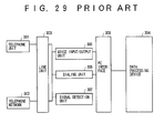
- FIG. 29 shows such a conventional communication support system.
- the conventional communication support system generally has an existing telephone unit 301, a data processing device 304, and a line unit 303.
- the telephone unit 301 is connected through the line unit 303 into the data processing device 304, and the line unit 303 is connected to a telephone network 302.
- the data processing device 304 is, for example, a personal computer.
- the telephone network 302 is, for example, a public switched telephone network.
- a voice input/output unit 305 a dialing unit 306 and a signal detection unit 307 are connected to the line unit 303. Further, a personal-computer (PC) interface unit 308 is provided between the data processing device 304 and the units 305 and 306.
- PC personal-computer
- the voice input/output unit 305 supplies a voice signal sent from the telephone unit 301 or the telephone network 302, to the data processing device 304 via the PC interface unit 308, and supplies a voice signal derived from digital data stored in the data processing device 304, to the telephone unit 301 or the telephone network 302.
- the dialing unit 306 provides an existing dialing function to transmit a call over the telephone network 302 to a destination terminal according to a telephone number input by an input device (such as a keyboard or a mouse) of the data processing device 304.
- the signal detection unit 307 detects various signals sent from a telephone line, such as a busy tone signal, a ring tone signal, a ring back tone signal, an on-hook signal, and an off-hook signal.
- the telephone services are provided by an existing telephone-service application program executed by the data processing device (or the personal computer).
- Such telephone services include, for example, voice recording and playback, file transmission, and telephone number entry.
- the application program installed in the data processing device 304 is executed.
- the user inputs the telephone number of the destination terminal and presses a dialing button on a monitor of the data processing device 304 by operating the input device (such as the keyboard or the mouse) of the data processing device 304.
- the user lifts a handset of the telephone unit 301 located away from the data processing device 304, and then the off-hook signal is detected by the signal detection unit 307.
- the telephone unit 301 is connected to the destination terminal by the line unit 303, and this enables the user to use the handset to communicate with a person of the destination terminal by voice.
- a voice recording function as one of the telephone services, is obtained by executing the application program on the data processing device 304
- the user of the data processing device 304 presses a recording start button on the monitor by operating the input device of the data processing device 304.
- the data processing device 304 acquires voice data from the telephone unit 301 or the telephone network 302 through the voice input/output unit 305.
- the application program on the data processing device 304 converts the voice data into digital data in a computer-readable format and stores the digital data in a memory of the data processing device 304.
- the application program continues to provide the voice recording until a recording end button on the monitor is pressed by the user.
- a playback function as one of the telephone services, is obtained by executing the application program on the data processing device 304
- the user of the data processing device 304 presses a playback start button on the monitor by operating the input device.
- the application program on the data processing device 304 converts the digital data stored in the memory of the device 304 into voice data, and supplies the voice data to the voice input/output unit 305.
- a voice signal is derived from the voice data by the voice input/output unit 305, and the voice signal is supplied to the telephone unit 301 or the telephone network 302 via the line unit 303.
- the application program continues to provide the playback function until a playback end button on the monitor is pressed by the user or the end of the data stored in the memory is detected.
- a telephone number entry function as one of the telephone services, is obtained by executing the application program on the data processing device 304
- the user of the data processing device 304 inputs a telephone number by operating the input device.
- the application program on the data processing device 304 stores the input telephone number in the memory.
- the application program is executed to carry out the telephone number entry processing when the user operates the keyboard or the mouse in connection with the monitor in an interactive manner.
- An object of the present invention is to provide an improved communication support system in which the above-mentioned problems are eliminated.
- Another object of the present invention is to provide a communication support system which enables the telephone user to use the telephone unit to obtain computer-assisted telephone services by remotely controlling the data processing device.
- Still another object of the present invention is to provide a communication control device for a communication support system including a telephone unit and a data processing device, which enables the telephone user to use the telephone unit to obtain computer-assisted telephone services by remotely controlling the data processing device.
- a further object of the present invention is to provide a method of executing a telephone service processing in a communication support system which provides computer-assisted telephone services for the telephone user of the telephone unit when the user remotely controls the data processing device by using the telephone unit.
- Another object of the present invention is to provide a computer readable medium storing program code instructions which causes a processor of a communication support system to execute a telephone service processing in response to a command signal sent by a telephone unit.
- a communication support system wherein a telephone unit is connected through a communication control device into a data processing device and the communication control device is connected to a telephone network, comprising: a command signal detection unit which detects a command signal sent by the telephone unit, the command signal indicating one of a plurality of telephone services; a telephone service recognition unit which determines which of the plurality of telephone services is indicated by the command signal from the telephone unit; and a telephone service processing unit which executes a telephone service processing for the telephone service determined by the telephone service recognition unit, the telephone service processing unit starting execution of the telephone service processing in response to control data from the command signal detection unit.
- a communication control device for a communication support system including a telephone unit and a data processing device wherein the communication control device is connected to a telephone network and the telephone unit sends a command signal indicating one of a plurality of telephone services, comprising: a line unit which connects the telephone unit through the communication control device into the data processing device and the telephone network; and a command signal detection unit which detects the command signal sent by the telephone unit, and transmits the command signal and control data to the data processing device so that the data processing device starts execution of a telephone service processing for the telephone service indicated by the command signal in response to the control data.
- a method of executing a telephone service processing in a communication support system wherein a telephone unit is connected through a communication control device into a data processing device and the communication control device is connected to a telephone network, comprising the steps of: detecting a command signal sent by the telephone unit, the command signal indicating one of a plurality of telephone services; transmitting the command signal and control data from the communication control device to the data processing device; determining which of the plurality of telephone services is indicated by the command signal from the telephone unit; and starting execution of a telephone service processing for the telephone service determined in said determining step, in response to the control data.
- the communication support system of the present invention it is possible to provide the computer-assisted telephone services for the telephone user when the telephone user uses the telephone unit to remotely control the data processing device.
- the communication support system of the present invention allows the telephone user to more easily transmit data to or receive data from other communication media such as the data processing device. Further, the communication support system of the present invention allows the telephone user to use a cordless telephone to remotely control the data processing device. It is no longer necessary that the user be located in front of the data processing device when obtaining the computer-assisted telephone services from the communication support system.
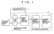
- FIG. 1 shows a communication support system of the present invention.
- the communication support system generally has a telephone unit (TU) 1, a communication control device (CCD) 2, a data processing device (DPD) 3, and a telephone network (TN) 4.
- the telephone unit 1 is connected through the communication control device 2 to the telephone network 4.
- the data processing device 3 is connected through the communication control device 2 to the telephone network 4.
- the telephone unit 1 provides existing voice transmission and reception functions and an existing dialing function.
- the communication control device (CCD) 2 comprises a line unit (LU) 5 and a command signal detection unit (CSD) 6.
- the LU 5 connects the telephone unit 1 to the telephone network 4, and connects the data processing device 3 to the telephone network 4.
- the communication control device (CCD) 2 provides connection of the telephone unit 1 to the telephone network 4 and connection of the data processing device 3 to the telephone network 4.
- the command signal detection unit (CSD) 6 provides detection of a command signal sent by the telephone unit 1.
- the command signal from the telephone unit 1 indicates one of a plurality of telephone services.
- the command signal detection unit (CSD) 6 detects the command signal sent by the telephone unit 1.
- the CCD 2 transmits the command signal from the telephone unit 1 and control data from the CSD 6 to the data processing device (DPD) 3.
- the data processing device (DPD) 3 comprises a telephone service processing unit (TSP) 7 and a telephone service recognition unit (TSR) 11.
- TSP telephone service processing unit
- TSR telephone service recognition unit
- the TSR 11 determines which of the telephone services is indicated by the command signal from the telephone unit 1.
- the TSP 7 executes a telephone service processing for the telephone service determined by the telephone service recognition unit 11.
- the TSP 7 starts executing the telephone service processing in response to the control data from the CSD 6.
- the line unit 5 connects the telephone unit 1 to the telephone network 4 and disconnects the command signal detection unit (CSD) 6 from the telephone unit 1.
- the line unit 5 connects the telephone unit 1 through the command signal detection unit (CSD) 6 into the DPD 3 and the telephone network 4.
- the CSD 6 detects the command signal sent by the telephone unit 1 when power is supplied to the CCD 2.
- the CCD 2 transmits the command signal from the telephone unit 1 and control data from the CSD 6 to the data processing device (DPD) 3.
- the telephone service recognition unit (TSR) 11 determines which of the telephone services is indicated by the command signal from the telephone unit 1.
- the telephone service processing unit (TSP) 7 executes a telephone service processing for the telephone service determined by the TSR 11.
- the TSP 7 starts executing the telephone service processing in response to the control data from the CSD 6.
- FIG. 2 shows allocation of specified values to each of DTMF command signals and dial-pulse command signals.
- FIG. 3 shows allocation of specified frequencies to frequency-based command signals.
- DTMF dual-tone multiple frequency
- dial pulse is used for the telephone unit 1 to transmit the command signal to the communication control device 2
- other specified values related to the ten-key pad of the telephone unit 1 may be allocated to a plurality of dial-pulse command signals, as shown in FIG. 2.
- the plurality of dial-pulse command signals respectively correspond to the plurality of telephone services.
- specified frequencies may be allocated to a plurality of frequency-based command signals as shown in FIG. 3.
- the plurality of frequency-based command signals respectively correspond to the plurality of telephone services.
- the present invention is not limited to the case of the DTMF command signals.
- the DTMF command signal may be replaced by the corresponding command signal without modification of the communication support system.
- the present invention can be applied to the communication support system in such cases in a similar manner.
- FIG. 4 shows a telephone unit, a communication control device and a data processing device in the communication support system of the present invention.
- the communication support system of FIG. 4 generally has a telephone unit 1, a communication control device (CCD) 2, a data processing device (DPD) 3, and a telephone network (TN) 4.
- the telephone unit 1 is connected through the CCD 2 into the DPD 3, and the CCD 2 is connected to the TN 4.
- the elements which are the same as corresponding elements in FIG. 1 are designated by the same reference numerals, and a description thereof will be omitted.
- the telephone unit 1 provides the existing voice transmission and reception functions and the existing dialing function.
- the telephone unit 1 of FIG. 4 comprises a radio circuit 8 and a cordless telephone 9.
- the cordless telephone 9 provides an existing radio signal transmission and reception function at a remote location of the radio circuit 8.
- the radio circuit 8 provides conversion of a radio signal from the cordless telephone 9 into voice data and conversion of voice data from the telephone line into a radio signal.
- the telephone unit 1 is not limited to the cordless telephone 9.
- the communication control device (CCD) 2 of FIG. 4 comprises a line unit (LU) 5, a command signal detection unit (CSD) 6, and a voice input/ output unit (VOICE IN/OUT) 10.
- the LU 5 connects the telephone unit 1 to the telephone network 4, and connects the data processing device 3 to the telephone network 4.
- the communication control device (CCD) 2 provides connection of the telephone unit 1 to the telephone network 4 and connection of the data processing device 3 to the telephone network 4.
- the command signal detection unit (CSD) 6 provides detection of a DTMF command signal sent by the telephone unit 1.
- the DTMF command signal from the telephone unit 1 indicates one of the plurality of telephone services.
- the command signal detection unit (CSD) 6 detects the DTMF command signal sent by the telephone unit 1.
- the CCD 2 transmits the DTMF command signal from the telephone unit 1 and the control data from the CSD 6 to the data processing device (DPD) 3.
- the voice input/output unit 10 supplies a voice signal sent from either the telephone unit 1 or the telephone network 4, to the DPD 3, and supplies a voice signal derived from digital data stored in the DPD 3, to either the telephone unit 1 or the telephone network 4.
- the data processing device (DPD) 3 comprises a telephone service processing unit (TSP) 7, a telephone service recognition unit (TSR) 11, a voice recording unit 12, a voice playback unit 13, a voice/data conversion unit 14, and a voice data storing unit 15.
- TSP telephone service processing unit
- TSR telephone service recognition unit
- voice recording unit 12 a voice recording unit 12
- voice playback unit 13 a voice playback unit 13
- voice/data conversion unit 14 a voice data storing unit 15.
- the TSR 11 determines which of the telephone services is indicated by the DTMF command signal from the telephone unit 1.
- the TSP 7 executes a telephone service processing for the telephone service determined by the TSR 11.
- the TSP 7 starts executing the telephone service processing in response to the control data from the CSD 6.
- the TSP 7 controls the voice recording unit 12 so that the voice recording unit 12 executes a voice recording processing to record a voice signal on the connection line of the TU 1 and the TN 4.
- the voice/data conversion unit 14 converts the voice signal from the voice input/output unit 10 of the CCD 2 into voice data (or digital data) in a computer-readable format, and conversely converts the voice data into the voice signal.
- the voice data storing unit 15 stores the voice data from the voice/data conversion unit 14 in a memory of the DPD 3.
- the TSP 7 controls the voice playback unit 13 so that the voice playback unit 13 executes a voice playback processing to reproduce the voice signal from the voice data stored in the memory.
- the reproduced voice signal is transmitted from the voice/data conversion unit 14 to the voice input/ output unit 10 of the CCD 2.
- the data processing device (DPD) 3 provides the telephone services, such as the voice recording and playback, based on the DTMF command signal sent by the telephone unit 1 when the telephone user uses the telephone unit 1 to remotely control the data processing device (DPD) 3.
- the communication support system of FIG. 4 allows the telephone user to more easily transmit data to or receive data from other communication media such as the data processing device. Further, the communication support system of FIG. 4 allows the telephone user to use the cordless telephone 9 in the telephone unit 1 to remotely control the data processing device (DPD) 3. It is no longer necessary that the user be located in front of the DPD 3 when obtaining the telephone services from the communication support system.
- the line unit 5 connects the telephone unit 1 to the telephone network 4 and disconnects the command signal detection unit (CSD) 6 from the telephone unit 1.
- the line unit 5 connects the telephone unit 1 through the command signal detection unit (CSD) 6 into the DPD 3 and the telephone network 4.
- the CSD 6 detects the DTMF command signal sent by the telephone unit 1 when power is supplied to the CCD 2.
- the CCD 2 notifies the DPD 3 that an event has occurred due to the DTMF command signal.
- the CCD 2 transmits the command signal from the telephone unit 1 and the control data from the CSD 6 to the DPD 3.
- the telephone service recognition unit (TSR) 11 determines which of the telephone services is indicated by the command signal from the telephone unit 1.
- the telephone service processing unit (TSP) 7 executes a telephone service processing for the telephone service determined by the TSR 11.
- the TSP 7 starts executing the telephone service processing in response to the control data from the CSD 6.
- the TSR 11 determines that a recording start processing is indicated by the DTMF command signal.
- the TSP 7 executes the recording start processing so that the voice recording unit 12 is controlled to start performing the voice recording.
- the TSR 11 determines that a recording end processing is indicated by the DTMF command signal.
- the TSP 7 executes the recording end processing so that the voice recording unit 12 is controlled to finish the voice recording.
- the TSR 11 determines that a playback start processing is indicated by the DTMF command signal.
- the TSP 7 executes the playback start processing so that the voice playback unit 13 is controlled to start performing the voice playback.
- the TSR 11 determines that a playback end processing is indicated by the DTMF command signal.
- the TSP 7 executes the playback end processing so that the voice playback unit 13 is controlled to finish the voice playback.
- the voice data storing unit 15 stores the voice data from the voice/data conversion unit 14 in the memory of the DPD 3.
- the voice playback processing is carried out by the voice playback unit 13
- the voice data stored in the memory is read out, and the voice signal is reproduced from the voice data by the voice/data conversion unit 14.
- the reproduced voice signal is transmitted from the voice/data conversion unit 14 to the voice input/output unit 10 of the CCD 2.
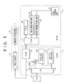
- FIG. 5 shows a telephone unit, a communication control device and a data processing device in the communication support system of the present invention.
- the communication support system of FIG. 5 generally has a telephone unit 1, a communication control device (CCD) 2, a data processing device (DPD) 3, and a telephone network (TN) 4.
- the telephone unit 1 is connected through the CCD 2 into the DPD 3, and the CCD 2 is connected to the TN 4.
- the elements which are the same as corresponding elements in FIG. 1 are designated by the same reference numerals, and a description thereof will be omitted.
- the telephone unit 1 provides the existing voice transmission and reception functions and the existing dialing function.
- the telephone unit 1 of FIG. 5 comprises a radio circuit 8 and a cordless telephone 9.
- the cordless telephone 9 provides an existing radio signal transmission and reception function at a remote location of the radio circuit 8.
- the radio circuit 8 provides conversion of a radio signal from the cordless telephone 9 into voice data and conversion of voice data from the telephone line into a radio signal.
- the telephone unit 1 is not limited to the cordless telephone 9.
- the communication control device (CCD) 2 of FIG. 5 comprises a line unit (LU) 5, a command signal detection unit (CSD) 6, a voice coding/decoding unit (VOICE CODEC) 16, a data modulator/demodulator unit (DATA MODEM) 17, and a switch (SW) 22.
- the LU 5 connects the telephone unit 1 to the telephone network 4, and connects the data processing device 3 to the telephone network 4.
- the communication control device (CCD) 2 provides connection of the telephone unit 1 to the telephone network 4 and connection of the data processing device 3 to the telephone network 4.
- the command signal detection unit (CSD) 6 provides detection of a DTMF command signal sent by the telephone unit 1.
- the DTMF command signal from the telephone unit 1 indicates one of the plurality of telephone services.
- the command signal detection unit (CSD) 6 detects the DTMF command signal sent by the telephone unit 1.
- the CCD 2 transmits the DTMF command signal from the telephone unit 1 and the control data from the CSD 6 to the data processing device (DPD) 3.
- the voice coding/decoding unit (VOICE CODEC) 16 provides coding of a voice signal sent by the telephone unit 1 into transmission data, and provides decoding of transmission data from the telephone network 4 into a voice signal for the telephone unit 1.
- the data modulator/demodulator unit (DATA MODEM) 17 provides modulation and demodulation of transmission data in the CCD 2.
- the switch (SW) 22 switches on and off a connection line of the voice codec 16 and the CCD 2.
- the switch 22 normally switches off the connection line of the voice codec 16 and the CCD 2 to disconnect the voice codec 16 from the TN 4.
- the switch 22 switches on the connection line of the voice codec 16 and the CCD 2 so that the voice codec 16 provides coding and decoding of voice data in the CCD 2.
- the data processing device (DPD) 3 comprises a telephone service processing unit (TSP) 7, a telephone service recognition unit (TSR) 18, a data receiving unit 19, a data transmitting unit 20, and a data storing unit 21.
- TSP telephone service processing unit
- TSR telephone service recognition unit
- the TSR 18 determines which of the telephone services is indicated by the DTMF command signal from the telephone unit 1.
- the TSP 7 executes a telephone service processing for the telephone service determined by the TSR 18.
- the TSP 7 starts executing the telephone service processing in response to the control data from the CSD 6.
- the TSP 7 controls the data receiving unit 19 during a file transmission processing, so that the data receiving unit 19 receives transmission data from a telephone line connected to the telephone network 4.
- the data storing unit 21 stores the transmission data received by the data receiving unit 19, in a memory of the DPD 3.
- the TSP 7 controls the data transmitting unit 20 during the file transmission processing, so that the data transmitting unit 20 transmits the transmission data, stored in the memory, to the telephone line connected to the telephone network 4.
- the data processing device (DPD) 3 provides the telephone service, such as the file transmission, based on the DTMF command signal sent by the telephone unit 1 when the telephone user uses the telephone unit 1 to remotely control the data processing device (DPD) 3.
- the communication support system of FIG. 5 allows the telephone user to more easily transmit data to or receive data from other communication media such as the data processing device. Further, the communication support system of FIG. 5 allows the telephone user to use the cordless telephone 9 in the telephone unit 1 to remotely control the data processing device (DPD) 3. It is no longer necessary that the user be located in front of the DPD 3 when obtaining the file transmission service from the communication support system.
- the line unit 5 connects the telephone unit 1 to the telephone network 4 and disconnects the command signal detection unit (CSD) 6 from the telephone unit 1.
- the line unit 5 connects the telephone unit 1 through the command signal detection unit (CSD) 6 into the DPD 3 and the telephone network 4.
- the CSD 6 detects the DTMF command signal sent by the telephone unit 1 when power is supplied to the CCD 2.
- the CCD 2 notifies the DPD 3 that an event has occurred due to the DTMF command signal.
- the CCD 2 transmits the command signal from the telephone unit 1 and the control data from the CSD 6 to the DPD 3.
- the telephone service recognition unit (TSR) 18 determines which of the telephone services is indicated by the command signal from the telephone unit 1.
- the telephone service processing unit (TSP) 7 executes a telephone service processing for the telephone service determined by the TSR 18.
- the TSP 7 starts executing the telephone service processing in response to the control data from the CSD 6.
- the TSR 18 determines that a file transmission start processing is indicated by the DTMF command signal.
- the TSP 7 executes the file transmission start processing so that the data receiving unit 19 and the data transmitting unit 20 are controlled to start performing the file transmission.
- the TSR 18 determines that a file transmission end processing is indicated by the DTMF command signal.
- the TSP 7 executes the file transmission end processing so that the data receiving unit 19 and the data transmitting unit 20 are controlled to finish the file transmission.
- the reception of the transmission data is automatically carried out by the DPD 3, and does not require the remote control by the telephone unit 1.
- the data storing unit 21 stores the data sent to the DPD 3 by the data modem 17 of the CCD 2, in the memory of the DPD 3.
- the transmission data transmitted by the data transmitting unit 20 the transmission data stored in the memory is read out and transmitted to the data modem 17 of the CCD 2.
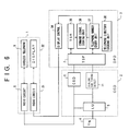
- FIG. 6 shows a telephone unit, a communication control device and a data processing device in the communication support system of the present invention.
- the communication support system of FIG. 6 generally has a telephone unit 1, a communication control device (CCD) 2, a data processing device (DPD) 3, and a telephone network (TN) 4.
- the telephone unit 1 is connected through the CCD 2 into the DPD 3, and the CCD 2 is connected to the TN 4.
- the elements which are the same as corresponding elements in FIG. 1 are designated by the same reference numerals, and a description thereof will be omitted.
- the telephone unit 1 provides the existing voice transmission and reception functions and the existing dialing function.
- the telephone unit 1 of FIG. 6 comprises a radio circuit 8, a cordless telephone 9, a radio circuit 31, and a display 32.
- the cordless telephone 9 provides the existing radio signal transmission and reception function at a remote location of the radio circuit 8.
- the radio circuit 8 provides conversion of a radio signal from the cordless telephone 9 into voice data and conversion of voice data from the telephone line into a radio signal.
- the display 32 provides, for the telephone user of the telephone unit 1, a message sent by the DPD 3 when one of the telephone services such as the telephone number entry is provided.
- the radio circuit 31 provides conversion of a radio signal from the DPD 3 into display data in a format suitable for the display 32 to display the data. According to the present invention, the telephone unit 1 is not limited to the cordless telephone 9.
- the communication control device (CCD) 2 of FIG. 6 comprises a line unit (LU) 5, a command signal detection unit (CSD) 6, and a dialing end timing detection unit 33.
- the LU 5 connects the telephone unit 1 to the telephone network 4, and connects the data processing device 3 to the telephone network 4.
- the communication control device (CCD) 2 provides connection of the telephone unit 1 to the telephone network 4 and connection of the data processing device 3 to the telephone network 4.
- the command signal detection unit (CSD) 6 provides detection of a DTMF command signal sent by the telephone unit 1.
- the DTMF command signal from the telephone unit 1 indicates one of the plurality of telephone services.
- the command signal detection unit (CSD) 6 detects the DTMF command signal sent by the telephone unit 1.
- the CCD 2 transmits the DTMF command signal from the telephone unit 1 and the control data from the CSD 6 to the data processing device (DPD) 3.
- the dialing end timing detection unit 33 provides detection of a dialing end timing based on a condition of a telephone line from the telephone unit 1.
- the data processing device (DPD) 3 comprises a telephone service processing unit (TSP) 7, a display control unit 34, a telephone service recognition unit (TSR) 35, a command signal storing unit 36, a telephone number entry unit 37, and a telephone directory storing unit 38.
- TSP telephone service processing unit
- TSR telephone service recognition unit
- the TSR 35 determines which of the telephone services is indicated by the DTMF command signal from the telephone unit 1.
- the TSP 7 executes a telephone number entry processing for the telephone service determined by the TSR 35.
- the TSP 7 starts executing the telephone number entry processing in response to the control data from the CSD 6.
- the command signal storing unit 36 stores the DTMF command signal in the memory of the DPD 3.
- the TSP 7 controls the telephone number entry unit 37 so that the telephone number entry unit 37 executes the telephone number entry processing to register the input telephone number (related to the destination terminal) from the telephone unit 1 in a telephone directory of the memory.
- the TSP 7 controls the display control unit 34 when the dialing end timing is detected by the dialing end timing detection unit 33, so that the display control unit 34 generates a confirmation message and causes the display 32 to display the input telephone number and the confirmation message.
- the telephone directory storing unit 38 stores the telephone directory updated by the telephone number entry unit 37 in the memory.
- the data processing device (DPD) 3 provides the telephone service, such as the telephone number entry, based on the DTMF command signal sent by the telephone unit 1 when the telephone user uses the telephone unit 1 to remotely control the data processing device (DPD) 3.
- the communication support system of FIG. 6 allows the telephone user to more easily transmit data to or receive data from other communication media such as the data processing device. Further, the communication support system of FIG. 6 allows the telephone user to use the cordless telephone 9 in the telephone unit 1 to remotely control the data processing device (DPD) 3. It is no longer necessary that the user be located in front of the DPD 3 when obtaining the telephone number entry service from the communication support system.
- the line unit 5 when power is not supplied to the CCD 2, the line unit 5 connects the telephone unit 1 to the telephone network 4 and disconnects the command signal detection unit (CSD) 6 from the telephone unit 1.
- the line unit 5 When power is supplied to the CCD 2, the line unit 5 connects the telephone unit 1 through the command signal detection unit (CSD) 6 into the DPD 3 and the telephone network 4.
- the CSD 6 detects the DTMF command signal sent by the telephone unit 1 when power is supplied to the CCD 2.
- the CCD 2 When the DTMF command signal accords with one of the DTMF command signals of FIG. 2, the CCD 2 notifies the DPD 3 that an event has occurred due to the DTMF command signal.
- the CCD 2 transmits the command signal from the telephone unit 1 and the control data from the CSD 6 to the DPD 3.
- the telephone service recognition unit (TSR) 35 determines which of the telephone services is indicated by the command signal from the telephone unit 1.
- the telephone service processing unit (TSP) 7 executes the telephone number entry processing for the telephone service determined by the TSR 35.
- the TSP 7 starts executing the telephone number entry processing in response to the control data from the CSD 6.
- the TSR 35 determines that the telephone number entry processing is indicated by the DTMF command signal.
- the TSP 7 executes the telephone number entry processing so that the telephone number entry unit 37 is controlled to start performing the telephone number entry processing.
- the command signal storing unit 36 stores the DTMF command signal in the memory.
- the display control unit 34 is controlled to display the input telephone number and the confirmation message on the display 32 of the telephone unit 1.
- the confirmation message provokes the telephone user to decide whether the input telephone number is to be registered into the telephone directory of the DPD 3.
- the telephone number entry unit 37 is controlled to register the input telephone number into the telephone directory.
- the telephone directory storing unit 38 stores the telephone directory updated by the telephone number entry unit 37 in the memory.
- the communication control device 2 in the communication support system of the present invention may be considered a modem or a terminal adapter that connects both the telephone unit 1 and the data processing device 3 to the telephone network 4.
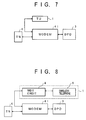
- FIG. 7 through FIG. 11 show various examples of construction of the elements of the communication support system. In the examples of FIGs. 7-11, a modem, a telephone system with a built-in modem, and a personal computer with a built-in telephone and modem are used to construct the communication support system of the present invention.
- FIG. 7 and FIG. 8 are essentially the same as the construction of the elements of the communication support system shown in FIGs. 1, 4, 5, and 6.
- a modem 41 is substituted for the communication control device 2 in the communication support system of the present invention.
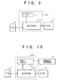
- FIG. 9 utilizes a telephone system 42 having a built-in modem.
- the modem 41 contained in the telephone system 42 is substituted for the communication control device 2 in the communication support system of the present invention.
- FIG. 10 utilizes a telephone system 43 having a built-in modem.
- the modem 41 contained in the telephone system 43 is substituted for the communication control device 2 in the communication support system of the present invention.
- FIG. 11 utilizes a personal computer 44 having a built-in telephone and modem.
- the modem 41 and the data processing device 3 contained in the personal computer 44 are substituted for the communication control device 2 and the data processing device 3 in the communication support system of the present invention.
- FIG. 12 shows one embodiment of the communication control device in the communication support system of the present invention.
- one of the telephone services including the voice recording and playback, file transmission and telephone number entry, is provided when the user on the telephone unit remotely controls the data processing device by transmitting a DTMF command signal from the telephone unit to the data processing device via the communication control device.
- the communication support system generally has a telephone unit (TU) 101, a communication control device (CCD) 118, a data processing device (DPD) 112, and a telephone network (TN) 102.
- the TU 101 is connected through the CCD 118 into the DPD 112, and the CCD 118 is connected to the TN 102.
- a PC interface unit 111 is provided between the CCD 118 and the DPD 112.
- the CCD 118 in the present embodiment comprises a relay 103, a relay control unit (RCU) 104, a DTMF detection unit 105, a voice input/output unit (VOICE IN/OUT) 106, a voice coding/decoding unit (VOICE CODEC) 107, a data modulator/demodulator unit (DATA MODEM) 108, a central processing unit (CPU) 109, and a bus 110.
- the CCD 118 further comprises a switch (SW) 113, a signal detection unit (SIGNAL DETECT) 114, a direct-current detection unit (DC DETECT) 116, and a direct-current detection unit (DC DETECT) 117.
- a display 115 is provided at a location of the telephone unit 101 and connected to the DPD 112.
- the execution of one of the telephone services is requested to the DPD 112 by the CCD 118 based on a corresponding one of a plurality of DTMF command signals sent from the telephone unit 101.
- the TU 101 provides the existing voice signal transmission and receiving functions and the existing dialing function.
- the TN 102 is, for example, a public switched telephone network.
- the CPU 109 receives signals from the elements of the CCD 118 connected through the bus 110, and controls these elements of the CCD 118.
- the DC detection unit 116 provides detection of an on-hook state of the TU 101.
- the DC detection unit 117 provides detection of a disconnection of the CCD 118 from the TN 102.
- a telephone-service processing program related to the flowcharts of FIGs. 14-25 (which will be described later) is program code instructions stored in a memory (not shown) of the CCD 118.
- the memory of the CCD 118 is, for example, a ROM (read-only memory).
- the memory corresponds to a processor readable medium in the claims.
- the processor readable medium includes any one of instruction storage devices, such as, for example, magnetic disks including floppy disks, optical disks including CD-ROMs, magneto-optical disks including MOs, semiconductor memory cards such as PC cards and miniature cards, and other types of computer usable devices and media.
- the memory of the CCD 118 may store encoded or non-encoded instructions.
- the instructions may be installed from a floppy disk (or a CD-ROM) to a hard disk drive (not shown) of the CCD 118 first, transferred to a RAM (not shown) of the CCD 118 and then read by the CPU 109.
- the memory of the CCD 118 may store either all or a part of the instructions related to the flowcharts of FIGs. 14-25.
- the relay control unit (RCU) 104 controls the relay 103 under control of the CPU 109.
- the relay 103 switches on or off a connection line between the TU 101 and the TN 102 when the relay 103 is controlled by the RCU 104.
- the relay 103 when power is supplied to place the CCD 118 in an initial condition, the relay 103 is set in an off-state by the RCU 104 so that the TU 101 and the CCD 118 are disconnected from the TN 102.
- the relay 103 is set in an on-state by the RCU 104 so that the TU 101 is connected through the CCD 118 into the TN 102.
- the DTMF detection unit 105 provides detection of a DTMF command signal sent by the TU 101.
- the voice input/output unit 106 provides, to the DPD 112, a voice signal on the connection line between the TU 101 and the TN 102.
- the voice codec 107 provides coding of a voice signal from the TU 101 into transmission data, and provides decoding of transmission data from the TN 101 into a voice signal for the TU 101.
- the data modem 108 provides modulation and demodulation of transmission data in the CCD 118.
- the PC interface unit 111 provides a personal-computer interface to connect the CCD 118 and the DPD 112.
- the DPD 112 provides execution of the telephone-service application program in order to provide the telephone services.
- the switch 113 switches on and off a connection line of the voice codec 107 and the CCD 118.
- the switch 113 normally switches off the connection line of the voice codec 107 and the CCD 118 to disconnect the voice codec 107 from the TN 102.
- the switch 113 switches on the connection line of the voice codec 107 and the CCD 118 so that the voice codec 107 provides coding and decoding of voice data in the CCD 118.
- the signal detection unit 114 provides detections of various signals sent from or to the telephone line (the TU 101 and the TN 102), the signals including a busy-tone signal (“BUSY”), a ring tone signal (“RING”), a ring-back-tone signal (“RBT”), an on-hook signal (“ON-HOOK”), and an off-hook signal (“OFF-HOOK”).
- BUSY busy-tone signal
- RING ring tone signal
- RBT ring-back-tone signal
- ON-HOOK on-hook signal
- OFF-HOOK off-hook signal
- the display 115 provides, for the telephone user of the telephone unit 101, a message sent by the DPD 112 when one of the telephone services such as the telephone number entry is provided by the DPD 112.
- FIG. 13 shows another embodiment of the communication control device in the communication support system of the present invention.
- the elements which are the same as corresponding elements in FIG. 12 are designated by the same reference numerals, and a description thereof will be omitted.
- one of the plurality of dial-pulse command signals is sent to the CCD 118 by the telephone unit 101, instead of the DTMF command signal, and a dial-pulse detection unit 205 is substituted for the DTMF detection unit 105 in the communication support system.
- the dial pulse detection unit 205 detects one of the plurality of dial-pulse command signals sent by the telephone unit 101.
- one of the telephone services including voice recording and playback, file transmission and telephone number entry, is provided in the same manner as in the embodiment of FIG. 12, when the user on the telephone unit remotely requests the data processing device to provide a corresponding telephone service by transmitting a dial-pulse command signal to the data processing device.
- a detection unit which detects one of the frequency-based command signals sent by the telephone unit 101 may be substituted for the DTMF detection unit 105 in the communication system of FIG. 12. Also, in such a case, one of the telephone services is provided in the same manner as in the embodiment of FIG. 12.
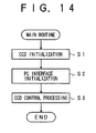
- FIG. 14 shows a main routine of a telephone service processing program executed by the central processing unit (CPU) 109 of the communication control device (CCD) 118 of FIG. 12.
- FIG. 15 shows a PC interface initialization in the main routine of FIG. 14.
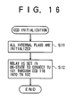
- FIG. 16 shows a CCD initialization in the main routine of FIG. 14.
- the program code instructions stored in the memory of the CCD 118, cause the CPU 109 to perform an initialization of the CCD 118 (S1).
- the program code instructions cause the CPU 109 to perform an initialization of the PC interface unit 111 (S2).
- the program code instructions cause the CPU 109 to perform a CCD control processing routine (S3) based on a signal sent by the TU 101, which will be described later.
- the program code instructions cause the CPU 109 to initialize all internal flags of the CCD 118 (S11). After the initialization of the internal flags of the above S11 is performed, the program code instructions cause the CPU 109 to set the relay 103 in the on-state by controlling the RCU 104 (S12). In this case, the relay 103 switches on the connection line between the TU 101 and the TN 102 so that the TU 101 is connected through the CCD 118 into the TN 102. After the setting of the relay 103 of the above S12 is performed, the CCD initialization of FIG. 16 is finished.
- the program code instructions cause the CPU 109 to set a status portion of the memory of the CCD 118 at a predetermined value (S21). After the setting of the status portion of the above S21 is performed, the program code instructions cause the CPU 109 to set a data portion of the memory of the CCD 118 at "00" (S22). After the setting of the data portion of the above S22 is performed, the program code instructions cause the CPU 109 to set a data strobe signal in an on-state (S23). After a given time period, the program code instructions cause the CPU 109 to set the data strobe signal in an off-state (S23). In this case, setting the status portion at the predetermined value indicates that data is currently included in the data portion of the memory. After the setting of the data strobe signal of the above S23 is performed, the PC interface initialization of FIG. 15 is finished.
- the CPU 109 of the CCD 118 simultaneously executes an interrupt processing routine in response to an interrupt signal.
- the interrupt signal is supplied to the CPU 109 by either the DPD 112 or the CCD 118.
- the DTMF detection unit 105 or the signal detection unit 114 supplies a detection signal to the CPU 109 as the interrupt signal.
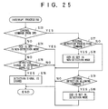
- FIG. 25 shows the interrupt processing routine executed by the CPU 109 of the CCD 118.
- the program code instructions cause the CPU 109 to determine whether the interrupt has occurred due to a control command sent by the DPD 112 (S73).
- the program code instructions cause the CPU 109 to determine whether the control command sent by the DPD 112 is an internal detection prohibiting command (S77).
- the program code instructions cause the CPU 109 to set the CCD 118 in a non-detection mode (S78).
- the CCD 118 is set in the non-detection mode, the DTMF detection unit 105 and the signal detection unit 114 are prohibited from detecting the content of the signal sent by the TU 101.
- the program code instructions cause the CPU 118 to determine whether the control command is an internal detection allowing command (S79). When the result of the above S79 is affirmative, the program code instructions cause the CPU 109 to set the CCD 118 in a detection mode (S80). When the CCD 118 is set in the detection mode, the DTMF detection unit 105 and the signal detection unit 114 are allowed to detect the content of the signal sent by the TU 101. The CCD 118 is initially set in the detection mode. After the setting of the CCD 118 of the above S80 is performed, the interrupt processing routine of FIG. 25 is finished.
- the program code instructions cause the CPU 109 to detect whether the CCD 118 is set in the non-detection mode (S74).
- the CCD 118 is normally set in the detection mode, such that the result of the above S74 is negative.
- the program code instructions cause the CPU 109 to detect whether a detection signal is internally supplied from the DTMF detection unit 105 or the signal detection unit 114 (S75).
- the program code instructions cause the CPU 109 to store the detection signal in the memory of the CCD 118 (S76).
- the detection signal is supplied to the CPU 109.
- the DTMF command signal sent by the TU 101 is detected by the DTMF detection unit 105
- the detection signal is supplied to the CPU 109.
- FIG. 17 shows the CCD control processing routine S3 in the main routine of FIG. 14.
- the program code instructions cause the CPU 109 to perform the CCD control processing routine S3 based on the signal sent by the TU 101.
- the program code instructions cause the CPU 109 to perform a detection signal reading (S31).
- FIG. 24 shows the detection signal reading S31 in the CCD control processing routine of FIG. 17.
- the program code instructions cause the CPU 109 to read out the detection signal (which has been stored in the above S76 in the interrupt processing of FIG. 25) from the memory of the CCD 118 (S69). After the reading of the detection signal of the above S69 is performed, the program code instructions cause the CPU 109 to determine whether the detection signal can be actually read out from the memory of the CCD 118 (S70). When the result of the above S70 is negative, the detection signal reading of FIG. 24 is finished.
- the program code instructions cause the CPU 109 to initialize a corresponding portion of the memory of the CCD 118 in which the detection signal was stored during the interrupt processing of FIG. 25 (S71). After the initialization of the above S71 is performed, the program code instructions cause the CPU 109 to return a code indicating the content of the detection signal read out in the above S69 (S72). After the returning of the code of the above S72 is performed, the detection signal reading of FIG. 24 is finished.
- the program code instructions cause the CPU 109 to determine which of the off-hook signal, the on-hook signal, the ring signal, the ring-back-tone ("RBT") signal, the busy-tone signal and the DTMF command signal is indicated by the return code obtained by the detection signal reading S31 (S32-S37 of FIG. 17).
- the program code instructions cause the CPU 109 to determine whether the off-hook signal is indicated by the return code (or detected by the signal detection unit 114) (S32). When the result of the above S32 is affirmative, the program code instructions cause the CPU 109 to perform an off-hook processing (S39).
- FIG. 18 shows the off-hook processing S39 in the CCD control processing routine of FIG. 17.
- the program code instructions cause the CPU 109 to set the status portion of the memory of the CCD 118 at the predetermined value (S51). In this case, setting the status portion at the predetermined value indicates that data is currently included in the data portion of the memory.
- the program code instructions cause the CPU 109 to set the data portion of the memory at "01" (S52). In this case, setting the data portion at "01" indicates that the off-hook signal is detected by the signal detection unit 114.
- the program code instructions cause the CPU 109 to notify the DPD 112 that the event has occurred due to the off-hook signal from the TU 101 (S53). After the off-hook processing S39 is performed, the program code instructions cause the CPU 109 to again perform the above detection signal reading S31.
- the program code instructions cause the CPU 109 to determine whether the on-hook signal is indicated by the return code (or detected by the signal detection unit 114) (S33). When the result of the above S33 is affirmative, the program code instructions cause the CPU 109 to perform an on-hook processing (S40).
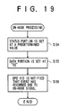
- FIG. 19 shows the on-hook processing S40 in the CCD control processing routine of FIG. 17.
- the program code instructions cause the CPU 109 to set the status portion of the memory of the CCD 118 at the predetermined value (S54).
- the program code instructions cause the CPU 109 to set the data portion of the memory at "02" (S55).
- setting the data portion at "02" indicates that the on-hook signal is detected by the signal detection unit 114.
- the program code instructions cause the CPU 109 to notify the DPD 112 that the event has occurred due to the on-hook signal from the TU 101 (S56).
- the program code instructions cause the CPU 109 to again perform the above detection signal reading S31.
- the program code instructions cause the CPU 109 to determine whether the ring signal is indicated by the return code (or detected by the signal detection unit 114) (S34). When the result of the above S34 is affirmative, the program code instructions cause the CPU 109 to perform a ring processing (S41).
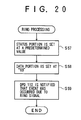
- FIG. 20 shows the ring processing S41 in the CCD control processing routine of FIG. 17.
- the program code instructions cause the CPU 109 to set the status portion of the memory of the CCD 118 at the predetermined value (S57). After the setting of the status portion of the above S57 is performed, the program code instructions cause the CPU 109 to set the data portion of the memory at "03" (S58). In this case, setting the data portion at "03" indicates that the ring signal is detected by the signal detection unit 114. After the setting of the data portion of the above S58 is performed, the program code instructions cause the CPU 109 to notify the DPD 112 that the event has occurred due to the ring signal from the TU 101 (S59). After the ring processing S41 is performed, the program code instructions cause the CPU 109 to again perform the above detection signal reading S31.
- the program code instructions cause the CPU 109 to determine whether the ring-back-tone signal is indicated by the return code (or detected by the signal detection unit 114) (S35). When the result of the above S35 is affirmative, the program code instructions cause the CPU 109 to perform a ring-back-tone (RBT) processing (S42).
- RBT ring-back-tone
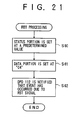
- FIG. 21 shows the ring-back-tone (RBT) processing S42 in the CCD control processing routine of FIG. 17.
- the program code instructions cause the CPU 109 to set the status portion of the memory of the CCD 118 at the predetermined value (S60).
- the program code instructions cause the CPU 109 to set the data portion of the memory at "04" (S61).
- setting the data portion at "04" indicates that the ring-back-tone signal is detected by the signal detection unit 114.
- the program code instructions cause the CPU 109 to notify the DPD 112 that the event has occurred due to the ring-back-tone signal from the TU 101 (S62).
- the program code instructions cause the CPU 109 to again perform the above detection signal reading S31.
- the program code instructions cause the CPU 109 to determine whether the busy-tone signal is indicated by the return code (or detected by the signal detection unit 114) (S36). When the result of the above S36 is affirmative, the program code instructions cause the CPU 109 to perform a busy-tone processing (S43).
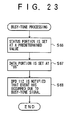
- FIG. 23 shows the busy-tone processing S43 in the CCD control processing routine of FIG. 17.
- the program code instructions cause the CPU 109 to set the status portion of the memory of the CCD 118 at the predetermined value (S66). After the setting of the status portion of the above S66 is performed, the program code instructions cause the CPU 109 to set the data portion of the memory at "05" (S67). In this case, setting the data portion at "05" indicates that the busy-tone signal is detected by the signal detection unit 114. After the setting of the data portion of the above S67 is performed, the program code instructions cause the CPU 109 to notify the DPD 112 that the event has occurred due to the busy-tone signal from the TU 101 (S68). After the busy-tone processing S43 is performed, the program code instructions cause the CPU 109 to again perform the above detection signal reading S31.
- the program code instructions cause the CPU 109 to determine whether the DTMF command signal is indicated by the return code (or detected by the DTMF detection unit 105) (S37). When the result of the above S37 is affirmative, the program code instructions cause the CPU 109 to perform a DTMF processing (S44).
- FIG. 22 shows the DTMF processing S44 in the CCD control processing routine of FIG. 17.
- the program code instructions cause the CPU 109 to set the status portion of the memory of the CCD 118 at the predetermined value (S63).
- the program code instructions cause the CPU 109 to set the data portion of the memory at a value indicated by the DTMF command signal (S64).
- the data portion of the memory is set at, for example, "*1" which is indicated by the DTMF command signal as shown in FIG. 2. In this case, setting the data portion at such a value indicates that the DTMF signal is detected by the DTMF detection unit 105.
- the program code instructions After the setting of the data portion of the above S64 is performed, the program code instructions cause the CPU 109 to notify the DPD 112 that the event has occurred due to the DTMF signal from the TU 101 (S65). After the DTMF processing S44 is performed, the program code instructions cause the CPU 109 to again perform the above detection signal reading S31.
- the program code instructions cause the CPU 109 to determine whether the end of the detection signal is indicated by the return code (or no detection signal is detected by the signal detection unit 114 or the DTMF detection unit 105) (S38). When the result of the above S38 is affirmative, the CCD control processing routine of FIG. 17 is finished. When the result of the above S38 is negative, the program code instructions cause the CPU 109 to again perform the above detection signal reading S31.
- FIG. 26 shows a main routine of a telephone-service application program executed by a central processor of the data processing device 112 in the communication support system of the present invention.
- the telephone-service application program related to the flowchart of FIG. 26 is program code instructions stored in a memory (not shown) of the data processing device (DPD) 112.
- the memory of the DPD 112 is, for example, a ROM (read-only memory).
- the memory of the DPD 112 corresponds to a processor readable medium in the claims.
- the processor readable medium includes any one of instruction storage devices, such as, for example, magnetic disks including floppy disks, optical disks including CD-ROMs, magneto-optical disks including MOs, semiconductor memory cards such as PC cards and miniature cards, and other types of computer usable devices and media.
- the memory of the DPD 112 may store encoded or non-encoded instructions.
- the instructions may be installed from a floppy disk (or a CD-ROM) to a hard disk drive (not shown) of the DPD 112 first, transferred to a RAM (not shown) of the DPD 112 and then read by the CPU of the DPD 112.
- the memory of the DPD 112 may store either all or a part of the instructions related to the flowchart of FIG. 26.
- the telephone-service application program as shown in FIG. 26 is executed by the central processor (which will be simply called the processor) of the DPD 112 when, in the CCD control processing routine of FIG. 17, one of the off-hook signal, the on-hook signal, the ring signal, the ring-back-tone signal, the busy-tone signal and the DTMF command signal is detected and the DPD 112 is notified that such an event has occurred.
- the central processor which will be simply called the processor
- the program code instructions cause the processor to perform an initialization of the telephone service application program in the DPD 112 (S101).
- the voice recording/playback start/end processing, the file transmission start/end processing, and the telephone number entry processing, related to the DPD 112 are initialized.
- the program code instructions cause the processor to perform a dialog screen display processing related to the display 115 (S102).
- the program code instructions cause the processor to perform an event waiting processing (S103).
- the processor is placed in a waiting condition in which the processor awaits occurrence of an event by the CPU 109 of the CCD 118.
- the program code instructions cause the processor to perform an event allocation processing (S104).
- S104 an event allocation processing
- one of the off-hook signal, the on-hook signal, the ring signal, the ring-back-tone signal, the busy-tone signal and the DTMF command signal is detected by the CPU 109 and the DPD 112 is notified by the CPU 109 that such an event has occurred, the processor of the DPD 112 allocates the event to one of a telephone condition dependence processing (S105), a DTMF processing (S106) and an end processing (S107).
- S105-S107 are performed during the main routine of FIG. 26, and the processing corresponding to the related one of the telephone services is actually performed by the DPD 112.
- the program code instructions When one of the off-hook signal, the on-hook signal, the ring signal, the ring-back-tone signal and the busy-tone signal is detected by the signal detection unit 114 of the CCD 118, the program code instructions cause the processor of the DPD 112 to perform the telephone condition dependence processing of the above S105. After the telephone condition dependence processing (S105) is performed, the program code instructions cause the processor to again perform the event waiting processing of the above S103.
- the program code instructions When the DTMF command signal is detected by the DTMF detection unit 105 of the CCD 118, the program code instructions cause the processor of the DPD 112 to perform the DTMF processing of the above S106. After the DTMF processing (S106) is performed, the program code instructions cause the processor to again perform the event waiting processing of the above S103.
- the program code instructions cause the processor to perform the end processing of the above S107. After the end processing (S107) is performed, the program code instructions cause the processor to again perform the event waiting processing of the above S103.
- FIG. 27 shows the telephone condition dependence processing S105 in the main routine of FIG. 26.
- the program code instructions cause the processor to determine which of the on-hook signal (“ON-HOOK”), the off-hook signal (“OFF-HOOK”), the ring-back-tone signal (“RBT”), the ring signal (“RING”) and the busy-tone signal (“BUSY”) has been detected by the signal detection unit 114 of the CCD 118 (S111, S113, S115, S123 and S125). Further, the program code instructions cause the processor to perform a processing corresponding to the event which is notified to the DPD 112 by the CPU 109 of the CCD 118.
- the program code instructions When it is notified to the DPD 112 that the event has occurred due to the on-hook signal from the TU 101 (the result of the above S111 is affirmative), the program code instructions cause the processor to start performing the telephone number entry processing (S112) which is related to one of the telephone services provided by the DPD 112.
- the program code instructions cause the processor to determine whether a dialing flag is set in an OFF state (S127).
- the dialing flag is normally set in an ON state when the dialing is being performed by the telephone user of the TU 101.
- the program code instructions cause the processor of the DPD 112 to display a telephone number, currently input by the telephone user of the TU 101, on the display 115 (S117). Further, the program code instructions cause the processor to display a confirmation message on the display 115 (S118). The confirmation message provokes the telephone user to decide whether the input telephone number is to be registered into the telephone directory of the DPD 112.
- the program code instructions cause the processor to be placed in a user request waiting condition (S119).
- the processor awaits inputting of a request for the telephone number entry by the telephone user.
- the program code instructions cause the processor to determine whether the request for the telephone number entry is input by the telephone user (S120).
- the program code instructions cause the processor to execute the telephone number entry processing (S121).
- the input telephone number from the TU 101 is actually registered into the telephone directory of the DPD 112.
- the program code instructions cause the processor to initialize a DTMF signal portion of the memory (S122). Further, the program code instructions cause the processor to set the dialing flag in the OFF state (S128). Then, the telephone condition dependence processing of FIG. 27 is finished.
- the program code instructions cause the processor to perform the initialization of the DTMF signal portion of the memory of the above S122. In this case, the telephone number entry processing of the above S121 is not performed by the processor.
- the program code instructions cause the processor to initialize the DTMF signal portion of the memory and set the dialing flag in the ON state (S114).
- the program code instructions cause the processor to start performing the telephone number entry processing (S116) in the same manner as in the above S112. Further, the program code instructions cause the processor to execute the above-described processing (the above S127, S117-S122 and S128).
- the program code instructions cause the processor to initialize the DTMF signal portion of the memory and set the dialing flag in the OFF state (S124).
- the program code instructions cause the processor to start performing the telephone number entry processing (S126) in the same manner as in the above S112. Further, the program code instructions cause the processor to execute the above-described processing (the above S127, S117-S122 and S128).
- FIG. 28 shows the DTMF processing S106 in the main routine of FIG. 26.
- the program code instructions cause the processor of the DPD 112 to perform the DTMF processing S106 in the main routine of FIG. 26.
- the processor carries out one of the telephone services including the recording/playback start/end processing and the file transmission start/end processing.
- the program code instructions cause the processor of the DPD 112 to determine whether the DTMF command signal detected by the DTMF detection unit 105 includes the DTMF "*" as a first portion thereof (S131).
- the program code instructions cause the processor to set a function mode flag in an ON state (S132).
- the processor is placed in a function mode in which the processor awaits detection of a second portion of the DTMF command signal.
- the program code instructions cause the processor to determine whether the processor is placed in the function mode (S133). When the processor is not placed in the function mode (the result of the above S133 is negative), the program code instructions cause the processor to detect that the dialing is being performed by the telephone user of the TU 101 (S147). After the S147 is performed, the program code instructions cause the processor to store the DTMF command signal in the DTMF signal portion of the memory (S148).
- the program code instructions cause the processor to start a function mode processing (S134).
- the processor determines what code or number is indicated by the second portion of the DTMF command signal (S135, S137, S139, S141, S143 and S145). Further, the processor of the DPD 112 carries out the related one of the telephone services (S136, S138, S140, S142, S144 and S146) based on the content of the second portion of the DTMF command signal.
- the program code instructions when the DTMF command signal includes the DTMF "1" as the second portion thereof (S135), the program code instructions cause the processor to perform a recording start processing (S136) which is one of the telephone services provided by the DPD 112.
- the program code instructions when the DTMF command signal includes the DTMF "2" as the second portion thereof (S137), the program code instructions cause the processor to perform a recording end processing (S138) which is one of the telephone services provided by the DPD 112.
- the program code instructions when the DTMF command signal includes the DTMF "3" as the second portion thereof (S139), the program code instructions cause the processor to perform a playback start processing (S140) which is one of the telephone services provided by the DPD 112.
- the program code instructions cause the processor to perform a playback end processing (S142) which is one of the telephone services provided by the DPD 112.
- the program code instructions cause the processor to perform a file transmission start processing (S144) which is one of the telephone services provided by the DPD 112.
- the program code instructions cause the processor to perform a file transmission end processing (S146) which is one of the telephone services provided by the DPD 112.
Landscapes
- Engineering & Computer Science (AREA)
- Signal Processing (AREA)
- Telephonic Communication Services (AREA)
- Selective Calling Equipment (AREA)
Applications Claiming Priority (3)
| Application Number | Priority Date | Filing Date | Title |
|---|---|---|---|
| JP9255794A JPH1198267A (ja) | 1997-09-19 | 1997-09-19 | 通信支援装置 |
| JP25579497 | 1997-09-19 | ||
| JP255794/97 | 1997-09-19 |
Publications (3)
| Publication Number | Publication Date |
|---|---|
| EP0903917A2 true EP0903917A2 (de) | 1999-03-24 |
| EP0903917A3 EP0903917A3 (de) | 2003-08-20 |
| EP0903917B1 EP0903917B1 (de) | 2007-09-26 |
Family
ID=17283732
Family Applications (1)
| Application Number | Title | Priority Date | Filing Date |
|---|---|---|---|
| EP98302408A Expired - Lifetime EP0903917B1 (de) | 1997-09-19 | 1998-03-30 | Kommunikationsunterstützungssystem für Fernsprechferngesteuerte Datenverarbeitungseinrichtung |
Country Status (5)
| Country | Link |
|---|---|
| US (1) | US6381310B2 (de) |
| EP (1) | EP0903917B1 (de) |
| JP (1) | JPH1198267A (de) |
| CN (1) | CN1198439C (de) |
| DE (1) | DE69838469T2 (de) |
Families Citing this family (6)
| Publication number | Priority date | Publication date | Assignee | Title |
|---|---|---|---|---|
| KR100750735B1 (ko) * | 2001-02-03 | 2007-08-22 | 삼성전자주식회사 | 홈네트워크내의 기기 제어장치 및 방법 및 이를 적용한홈네트워크 시스템 |
| WO2003009441A1 (en) * | 2001-07-19 | 2003-01-30 | Mitsubishi Denki Kabushiki Kaisha | Vacuum switch unit and switch gear |
| US6950498B1 (en) | 2003-10-08 | 2005-09-27 | America Online, Inc. | External detection of optional telephone services |
| JP2008277898A (ja) * | 2007-04-25 | 2008-11-13 | Fujitsu Ltd | 携帯電話機電話帳 |
| JP5245539B2 (ja) * | 2008-05-27 | 2013-07-24 | 富士通株式会社 | 仮想マシンの入出力エミュレーション機構 |
| JP5202280B2 (ja) * | 2008-12-19 | 2013-06-05 | 株式会社日立製作所 | 中継装置、通信システム及び通信方法 |
Family Cites Families (20)
| Publication number | Priority date | Publication date | Assignee | Title |
|---|---|---|---|---|
| CA1314965C (en) * | 1988-03-01 | 1993-03-23 | Gerald Molnar | Data interface for telephone system |
| US4918722A (en) * | 1988-05-11 | 1990-04-17 | Brooktrout Technology, Inc. | Control of electronic information delivery |
| JPH02272951A (ja) | 1989-04-14 | 1990-11-07 | Canon Inc | 情報処理装置 |
| JPH03191644A (ja) | 1989-12-21 | 1991-08-21 | Mitsubishi Electric Corp | コードレス電話装置 |
| JPH0461543A (ja) | 1990-06-29 | 1992-02-27 | Sharp Corp | テレビ電話装置 |
| US5291479A (en) * | 1991-07-16 | 1994-03-01 | Digital Technics, Inc. | Modular user programmable telecommunications system with distributed processing |
| JPH0556190A (ja) | 1991-08-28 | 1993-03-05 | Matsushita Electric Ind Co Ltd | テレビシステム |
| JPH0575823A (ja) | 1991-09-17 | 1993-03-26 | Matsushita Electric Ind Co Ltd | フアクシミリ装置 |
| US6121998A (en) * | 1992-02-19 | 2000-09-19 | 8×8, Inc. | Apparatus and method for videocommunicating having programmable architecture permitting data revisions |
| JP3049928B2 (ja) | 1992-03-17 | 2000-06-05 | 松下電器産業株式会社 | コードレス電話による電子機器の遠隔制御システム |
| US5402472A (en) * | 1992-04-23 | 1995-03-28 | Boston Technology, Inc. | Automated attendant for any combination of PBX, centrex, and single-line telephones |
| US5452289A (en) * | 1993-01-08 | 1995-09-19 | Multi-Tech Systems, Inc. | Computer-based multifunction personal communications system |
| DE69426751T2 (de) * | 1993-12-06 | 2001-09-06 | Canon Kk | Benutzerdefinierbares interaktives System |
| US5481596A (en) * | 1994-05-26 | 1996-01-02 | At&T Corp. | Auxiliary baseband telephone interface for an answering machine |
| JPH0830352A (ja) | 1994-07-12 | 1996-02-02 | Sony Corp | 情報処理装置 |
| US5524141A (en) * | 1994-09-22 | 1996-06-04 | Bell Communications Research, Inc. | System and method for providing directory information over a telephony network using ADSI |
| AU705525B2 (en) * | 1994-12-02 | 1999-05-27 | Voice Control Systems, Inc. | Intelligent call processing platform for home telephone system |
| JPH08237299A (ja) | 1995-02-28 | 1996-09-13 | Nec Corp | オムニメディア通信サービスシステム |
| JPH09116940A (ja) | 1995-10-19 | 1997-05-02 | Matsushita Electric Ind Co Ltd | コンピュータ・電話統合システム |
| JP3191644B2 (ja) | 1995-10-20 | 2001-07-23 | 松下電器産業株式会社 | 簡易型ガス吸収式鉛蓄電池およびその製造法 |
-
1997
- 1997-09-19 JP JP9255794A patent/JPH1198267A/ja active Pending
-
1998
- 1998-03-24 US US09/046,556 patent/US6381310B2/en not_active Expired - Fee Related
- 1998-03-30 DE DE69838469T patent/DE69838469T2/de not_active Expired - Fee Related
- 1998-03-30 EP EP98302408A patent/EP0903917B1/de not_active Expired - Lifetime
- 1998-04-17 CN CN98106662.3A patent/CN1198439C/zh not_active Expired - Fee Related
Also Published As
| Publication number | Publication date |
|---|---|
| DE69838469T2 (de) | 2008-02-14 |
| EP0903917B1 (de) | 2007-09-26 |
| EP0903917A3 (de) | 2003-08-20 |
| CN1212556A (zh) | 1999-03-31 |
| DE69838469D1 (de) | 2007-11-08 |
| JPH1198267A (ja) | 1999-04-09 |
| US6381310B2 (en) | 2002-04-30 |
| CN1198439C (zh) | 2005-04-20 |
| US20010043698A1 (en) | 2001-11-22 |
Similar Documents
| Publication | Publication Date | Title |
|---|---|---|
| US4995073A (en) | Communication apparatus and communication system having automatic attribution switching | |
| US5367564A (en) | Storage-and-forward apparatus | |
| US6044133A (en) | Communication support system for providing telephone services of a data processing device by a voice command sent by a telephone unit | |
| EP0903917B1 (de) | Kommunikationsunterstützungssystem für Fernsprechferngesteuerte Datenverarbeitungseinrichtung | |
| US5260991A (en) | Facsimile apparatus | |
| JP2912844B2 (ja) | 発呼モード切換え可能な通信システム及びそのシステムに用いられる端末装置 | |
| US7139088B2 (en) | Communication apparatus and communication method | |
| US7406162B2 (en) | Communication support system for providing security of telephone services of a data processing device for a telephone user | |
| US6240165B1 (en) | Communication support system in which a caller profile from a data processing device is transmitted to a telephone device upon incoming of a call | |
| JPH11136396A (ja) | 通信装置 | |
| JP2811025B2 (ja) | 複合型画像通信装置 | |
| US5953397A (en) | Computer system with mode switching function and method of controlling the same | |
| JP3192990B2 (ja) | 加入者端末機のラインインタフェース回路及びその制御方法 | |
| JP3637868B2 (ja) | Isdn通信装置 | |
| JPH08251261A (ja) | 情報処理装置 | |
| JP2002135440A (ja) | 通信装置およびその制御方法 | |
| US6456401B1 (en) | Communication apparatus capable of conducting remote diagnosis using communication circuit | |
| JP2006157978A (ja) | 通信支援装置、通信支援サービスの実行方法及び記憶媒体 | |
| JP2950197B2 (ja) | 通信装置 | |
| JPH10336342A (ja) | ファクシミリ装置 | |
| JP2006180553A (ja) | 通信支援装置、通信支援サービスの実行方法及び記憶媒体 | |
| JPH11308369A (ja) | 通信装置 | |
| JPH03217973A (ja) | ファクシミリ情報処理装置 | |
| JP2006180552A (ja) | 通信制御装置、通信制御方法及び記憶媒体 | |
| JPH0227859A (ja) | 画情報通信装置 |
Legal Events
| Date | Code | Title | Description |
|---|---|---|---|
| PUAI | Public reference made under article 153(3) epc to a published international application that has entered the european phase |
Free format text: ORIGINAL CODE: 0009012 |
|
| AK | Designated contracting states |
Kind code of ref document: A2 Designated state(s): AT BE CH DE DK ES FI FR GB GR IE IT LI LU MC NL PT SE |
|
| AX | Request for extension of the european patent |
Free format text: AL;LT;LV;MK;RO;SI |
|
| PUAL | Search report despatched |
Free format text: ORIGINAL CODE: 0009013 |
|
| AK | Designated contracting states |
Designated state(s): AT BE CH DE DK ES FI FR GB GR IE IT LI LU MC NL PT SE |
|
| AX | Request for extension of the european patent |
Extension state: AL LT LV MK RO SI |
|
| 17P | Request for examination filed |
Effective date: 20040216 |
|
| 17Q | First examination report despatched |
Effective date: 20040317 |
|
| AKX | Designation fees paid |
Designated state(s): DE FR GB |
|
| GRAP | Despatch of communication of intention to grant a patent |
Free format text: ORIGINAL CODE: EPIDOSNIGR1 |
|
| GRAS | Grant fee paid |
Free format text: ORIGINAL CODE: EPIDOSNIGR3 |
|
| GRAA | (expected) grant |
Free format text: ORIGINAL CODE: 0009210 |
|
| AK | Designated contracting states |
Kind code of ref document: B1 Designated state(s): DE FR GB |
|
| REG | Reference to a national code |
Ref country code: GB Ref legal event code: FG4D |
|
| REF | Corresponds to: |
Ref document number: 69838469 Country of ref document: DE Date of ref document: 20071108 Kind code of ref document: P |
|
| ET | Fr: translation filed | ||
| PGFP | Annual fee paid to national office [announced via postgrant information from national office to epo] |
Ref country code: GB Payment date: 20080328 Year of fee payment: 11 |
|
| PGFP | Annual fee paid to national office [announced via postgrant information from national office to epo] |
Ref country code: FR Payment date: 20080222 Year of fee payment: 11 Ref country code: DE Payment date: 20080408 Year of fee payment: 11 |
|
| PLBE | No opposition filed within time limit |
Free format text: ORIGINAL CODE: 0009261 |
|
| STAA | Information on the status of an ep patent application or granted ep patent |
Free format text: STATUS: NO OPPOSITION FILED WITHIN TIME LIMIT |
|
| 26N | No opposition filed |
Effective date: 20080627 |
|
| GBPC | Gb: european patent ceased through non-payment of renewal fee |
Effective date: 20090330 |
|
| REG | Reference to a national code |
Ref country code: FR Ref legal event code: ST Effective date: 20091130 |
|
| PG25 | Lapsed in a contracting state [announced via postgrant information from national office to epo] |
Ref country code: DE Free format text: LAPSE BECAUSE OF NON-PAYMENT OF DUE FEES Effective date: 20091001 |
|
| PG25 | Lapsed in a contracting state [announced via postgrant information from national office to epo] |
Ref country code: GB Free format text: LAPSE BECAUSE OF NON-PAYMENT OF DUE FEES Effective date: 20090330 Ref country code: FR Free format text: LAPSE BECAUSE OF NON-PAYMENT OF DUE FEES Effective date: 20091123 |