EP0903802A2 - Circulateur à constantes localisées - Google Patents
Circulateur à constantes localisées Download PDFInfo
- Publication number
- EP0903802A2 EP0903802A2 EP98410103A EP98410103A EP0903802A2 EP 0903802 A2 EP0903802 A2 EP 0903802A2 EP 98410103 A EP98410103 A EP 98410103A EP 98410103 A EP98410103 A EP 98410103A EP 0903802 A2 EP0903802 A2 EP 0903802A2
- Authority
- EP
- European Patent Office
- Prior art keywords
- circulator
- resonance
- circuit
- lumped element
- frequency
- Prior art date
- Legal status (The legal status is an assumption and is not a legal conclusion. Google has not performed a legal analysis and makes no representation as to the accuracy of the status listed.)
- Granted
Links
Images


Classifications
-
- H—ELECTRICITY
- H01—ELECTRIC ELEMENTS
- H01P—WAVEGUIDES; RESONATORS, LINES, OR OTHER DEVICES OF THE WAVEGUIDE TYPE
- H01P1/00—Auxiliary devices
- H01P1/32—Non-reciprocal transmission devices
- H01P1/38—Circulators
- H01P1/383—Junction circulators, e.g. Y-circulators
- H01P1/387—Strip line circulators
Definitions
- the present invention relates to a lumped element circulator used as a high frequency circuit element in for example a portable or mobile communication equipment. Particularly, the present invention relates to a lumped element circulator operable in a plurality of frequency bands.
- a circulator is an element for giving non-reciprocal characteristics to a high frequency circuit so as to suppress reflecting waves in the circuit.
- standing waves can be prevented from generation resulting that stable operations of the high frequency circuit can be expected. Therefore, in recent portable telephones, such non-reciprocal elements are usually provided for suppress standing waves from generation.
- a lumped element circulator having a plurality of operation bands has a circulator element with a plurality of signal ports and a grounded terminal, and resonance circuits connected between the signal ports and the grounded terminal, respectively, each of the resonance circuits having a plurality of resonance points.
- the number of the operation bands is equal to the number of the resonance points of each of the resonance circuits.
- the invention focuses attention on that, in a lumped element circulator, difference between eigenvalues of the circulator element excited by positive and negative rotational eigenvectors is 120 degrees (in case of three port circulator) without reference to frequency.
- a network exhibiting a frequency performance for satisfying circulator conditions in a plurality of necessary frequency bands is connected to each port so that the circulator can operate in the plurality of frequency bands. This is realized by inserting a resonance circuit having a plurality of resonance points between each of the signal ports and the grounded terminal of the circulator element of the lumped element circulator.
- a lumped element circulator alone can suppress any standing wave from generation in a plurality of frequency bands.
- the circulator according to the present invention can be alone used to suppress standing wave from generation in a plurality of frequency bands.
- each of the resonance circuits is a series-parallel resonance circuit having at least one pair of a series resonance point and a parallel resonance point.
- the number of the operation bands is equal to the number of the pair of the series resonance point and the parallel resonance point plus one.
- Fig. 1 schematically illustrates a structure of a three port type dual band lumped element circulator of a preferred embodiment according to the present invention.
- reference numerals 10 and 11 denote integrated ferromagnetic material disks, made of for example ferrite, sandwiching three pairs of two parallel drive conductors 12 1 , 12 2 and 12 3 which are insulated from each other, 13 and 14 denote shielding electrodes formed on outer surfaces of the respective ferromagnetic material disks 10 and 11, 15 denotes a grounded electrode, 16 1 , 17 1 , 16 2 and 17 2 denote resonance capacitors, and 18 1 and 18 2 denote resonance coils, respectively.
- the pairs of drive conductors 12 1 , 12 2 and 12 3 constitute three inductors which extend to three directions 120 degrees apart and form a trigonally symmetric shape.
- the resonance capacitor 17 1 and the resonance coil 18 1 constitute a series resonance circuit.
- This series resonance circuit and the resonance capacitor 16 1 are connected in parallel between the signal port of the drive conductor pair 12 1 and the grounded electrode 15.
- the resonance capacitor 17 2 and the resonance coil 18 2 constitute a series resonance circuit.
- This series resonance circuit and the resonance capacitor 16 2 are connected in parallel between the signal port of the drive conductor pair 12 2 and the grounded electrode 15.
- a series resonance circuit which is constituted by the resonance capacitor 17 3 and the resonance coil 18 3 , and the resonance capacitor 16 3 (Fig. 2) are connected in parallel between the signal port of the drive conductor pair 12 3 and the grounded electrode 15.
- Excitation permanent magnets (not shown) are provided on the element 10 and under the element 11, respectively.
- FIG. 2 An equivalent circuit of the lumped element circulator of the embodiment of Fig. 1 is illustrated in Fig. 2.
- this lumped element circulator is equivalent to a circuit in which, between signal ports 21 1 , 21 2 and 21 3 of an ideal circulator 20 and the grounded electrode 15, a series-parallel resonance circuit constituted by the resonance capacitor 16 1 with a capacitance C 0 , the resonance capacitor 17 1 with a capacitance C 1 , the resonance coil 18 1 with an inductance L 1 and an inductor L, a series-parallel resonance circuit constituted by the resonance capacitor 16 2 with a capacitance C 0 , the resonance capacitor 17 2 with a capacitance C 1 , the resonance coil 18 2 with an inductance L 1 and an inductor L, and a series-parallel resonance circuit constituted by the resonance capacitor 16 3 with a capacitance C 0 , the resonance capacitor 17 3 with a capacitance C 1 , the resonance coil 18 3 with an inductance L 1 and an
- the ideal circulator 20 is a virtual circuit element operating as a circulator over whole range from zero frequency to infinite frequency.
- the circuit composed of this ideal circulator 20 and the inductors L corresponds to non-reciprocal inductance of the meshed drive conductors 12 1 , 12 2 and 12 3 constructed in the circulator element.
- the resonance circuit providing a necessary effective capacitance at required frequencies is connected between each of the signal ports 21 1 , 21 2 and 21 3 and the grounded electrode 15.
- this lumped element circulator can operate as a circulator in a plurality of frequency bands, as described hereinafter in detail.
- FIG. 3 An equivalent circuit of a conventional lumped element circulator is illustrated in Fig. 3.
- the conventional lumped element circulator is equivalent to a circuit in which parallel resonance circuits 32 1 , 32 2 and 32 3 with a center frequency f 0 are connected to signal ports 31 1 , 31 2 and 31 3 of an ideal circulator 30, respectively.
- the ideal circulator 30 is a virtual circuit element operating as a circulator over whole range from zero frequency to infinite frequency.
- the circuit composed of this ideal circulator 30 and inductors L in the parallel resonance circuits 32 1 , 32 2 and 32 3 corresponds to non-reciprocal inductance of meshed drive conductors constructed in a circulator element of the conventional lumped element circulator.
- Figs. 4a and 4b illustrate a structure of an inductor part of the conventional lumped element circulator
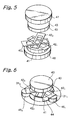
- Fig. 5 illustrates a structure of a circulator element part of this conventional lumped element circulator
- Fig. 6 illustrates an assembled structure in which resonance capacitors are connected to the circulator element shown in Fig. 5.
- integrated ferromagnetic material disks 40 and 41 sandwich three pairs of two parallel drive conductors 42 1 , 42 2 and 42 3 which are insulated from each other. Shielding electrodes 43 and 44 are formed on outer surfaces of the respective ferromagnetic material disks 40 and 41.
- the drive conductor pairs 42 1 , 42 2 and 42 3 constitute three inductors which extend to three directions 120 degrees apart and form a trigonally symmetric shape.
- Resonance capacitors 46 1 , 46 2 and 46 3 are connected between signal ports 31 1 , 31 2 and 31 3 of the drive conductor pairs 42 1 , 42 2 and 42 3 , respectively.
- Excitation permanent magnets 47 and 48 are provided on the element 40 and under the element 41, respectively.
- Fig. 4a a section of the inductor (drive conductor 42 1 ) connected to one signal port (signal port 31 1 for example) and excited magnetic fields are illustrated.
- inductance of this inductor (drive conductor pair 42 1 ) is L 0
- magnetic field 49 excited by current flowing through the remaining two inductors (drive conductor pairs 42 2 and 42 3 ) will cross the inductor 42 1 connected to the signal port 31 1 .
- inductance viewed from this signal port 31 1 has to be calculated in consideration of the influence of the magnetic field 49.
- reflection coefficients of respective signal ports can be equalized with each other by applying specially combined advance waves to the respective signal ports.
- Vectors indicating the advance waves which satisfy this condition are called as eigenvectors, and the reflection coefficients are called as eigenvalues.
- eigenvectors and n eigenvalues corresponding to the respective vectors are existed. Therefore, in the three ports circulator, three eigenvectors u 1 , u 2 and u 3 and three eigenvalues s 1 , s 2 and s 3 corresponding to the respective vectors are existed. These eigenvectors should have the following values.
- s 2 s 1 e j 2 ⁇ 3
- s 3 s 1 e -j 2 ⁇ 3
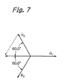
- excitation magnetic fields H 1 , H 2 and H 3 for the respective eigenvectors u 1 , u 2 and u 3 are obtained by following equations (5);
- inductances of the conductors viewed from the respective signal ports L 1 , L 2 and L 3 for the eigenvectors u 1 , u 2 and u 3 are given as following equation (6);
- L 1 0,
- the inductance L 1 for the eigenvector u 1 is 0 as indicated in the equation (6).
- the eigenvalue s 1 is located at the right end point (1,0) on the Smith chart and independent to frequency. Therefore, after the applied magnetic field is adjusted so that the eigenvalues s 2 and s 3 have 120 degrees apart from each other on the Smith chart, if the position of the eigenvalues s 2 and s 3 are moved by adding capacitors to the respect signal ports so that the angle of each of the eigenvalues s 2 and s 3 with respect to the eigenvalue s 1 becomes 120 degrees as shown in Fig. 8, a complete circulator at that frequency can be obtained.
- the capacitance C can be obtained by following equation (17).
- a circulator is realized by connecting a circuit exhibiting the capacitance C at the frequency f 1 to each port.
- a circulator operating at both frequencies f 1 and f 2 can be obtained by connecting to each port of this circulator a circuit exhibiting a capacitance C at the frequency f 1 and also exhibiting a capacitance (f 1 /f 2 ) 2 C at the frequency f 2 .
- a series-parallel resonance circuit shown in Fig. 10 is capacitive under and above the resonance frequency. Thus, if the operating frequencies of this circuit are adjusted at frequencies under and above its series-parallel resonance frequency, this circuit will meet the above-mentioned condition.
- a dual band lumped element circulator according to this embodiment is practically designed and fabricated.
- the resonance capacitance C can be obtained by using the equation (17) as follows.
- a circulator element which satisfies this condition is fabricated and thus a dual band lumped element circulator operable at octave frequencies of 300 MHz and 600 MHz is formed.
- the dual band circulator thus fabricated has a transfer characteristics as shown in Fig. 12. As will be understood from the figure, this measured transfer characteristics matches with the designed characteristics very well.
- the aforementioned embodiment concerns a dual band circulator with two operation bands. It is known however that in a two-terminal resonance circuit with a plurality of resonance points, capacitive regions can be made by the number equal to the number of its resonance point pairs plus one. Therefore, it is apparent that a circulator with three or more operation bands at desired frequencies can be constructed by modifying the aforementioned embodiment.
- Fig. 13 illustrates a resonance circuit connected to each port of a lumped element circulator of another embodiment according to the present invention.
- this series-parallel resonance circuit has a series resonance circuit constituted by a resonance coil 131 with an inductance L1 and a resonance capacitor 132 with a capacitance C1 connected in series, a resonance capacitor 133 with a capacitance C 0 connected in parallel with the series resonance circuit, a resonance coil 134 with an inductance L 2 connected in series with the series resonance circuit, and a resonance capacitor 135 with a capacitance C 2 connected in parallel with the resonance coil 134 and the series resonance circuit.
- This two-terminal series-parallel resonance circuit is connected between each signal port and the grounded electrode of the circulator as well as the aforementioned embodiment.
- This series-parallel resonance circuit has two pairs of series resonance point and parallel resonance point, and therefore is used for a circulator which requires three operation bands.
Landscapes
- Non-Reversible Transmitting Devices (AREA)
- Control Of Motors That Do Not Use Commutators (AREA)
Applications Claiming Priority (3)
| Application Number | Priority Date | Filing Date | Title |
|---|---|---|---|
| JP26921197A JP3959797B2 (ja) | 1997-09-17 | 1997-09-17 | 集中定数型サーキュレータ |
| JP26921197 | 1997-09-17 | ||
| JP269211/97 | 1997-09-17 |
Publications (3)
| Publication Number | Publication Date |
|---|---|
| EP0903802A2 true EP0903802A2 (fr) | 1999-03-24 |
| EP0903802A3 EP0903802A3 (fr) | 2001-04-11 |
| EP0903802B1 EP0903802B1 (fr) | 2003-01-29 |
Family
ID=17469228
Family Applications (1)
| Application Number | Title | Priority Date | Filing Date |
|---|---|---|---|
| EP98410103A Expired - Lifetime EP0903802B1 (fr) | 1997-09-17 | 1998-09-16 | Circulateur à constantes localisées |
Country Status (4)
| Country | Link |
|---|---|
| US (1) | US6236285B1 (fr) |
| EP (1) | EP0903802B1 (fr) |
| JP (1) | JP3959797B2 (fr) |
| DE (1) | DE69811027T2 (fr) |
Cited By (7)
| Publication number | Priority date | Publication date | Assignee | Title |
|---|---|---|---|---|
| EP1041664A1 (fr) * | 1999-03-30 | 2000-10-04 | Tokin Corporation | Dispositif de circuit non réciproque à bande double |
| GB2354884A (en) * | 1996-12-12 | 2001-04-04 | Racal Mesl Ltd | Microwave circulator / isolator with separate lumped element resonators |
| FR2802378A1 (fr) * | 1999-12-09 | 2001-06-15 | Murata Manufacturing Co | Dispositif a circuit non reciproque et dispositif de telecommunications l'utilisant |
| GB2361813A (en) * | 2000-03-13 | 2001-10-31 | Murata Manufacturing Co | Nonreciprocal circuit device with improved attenuation |
| US6597253B2 (en) * | 2000-05-26 | 2003-07-22 | Murata Manufacturing Co., Ltd. | Nonreciprocal circuit device and communication apparatus including the same |
| US6798311B2 (en) * | 1999-11-30 | 2004-09-28 | Murata Manufacturing Co., Ltd. | Nonreciprocal circuit device with a solenoid-shaped inductor generating perpendicular flux |
| US6861922B2 (en) | 2000-03-02 | 2005-03-01 | Murata Manufacturing Co., Ltd. | Nonreciprocal circuit device including two series resonant circuits having differing resonant frequencies |
Families Citing this family (5)
| Publication number | Priority date | Publication date | Assignee | Title |
|---|---|---|---|---|
| JP3558003B2 (ja) * | 2000-03-03 | 2004-08-25 | 株式会社村田製作所 | 非可逆回路素子および通信装置 |
| JP4478680B2 (ja) * | 2003-07-14 | 2010-06-09 | フォトニックシステムズ, インコーポレイテッド | 送受信兼用信号インターフェース |
| JP2008154201A (ja) * | 2006-07-07 | 2008-07-03 | Murata Mfg Co Ltd | 送信装置 |
| TWI407692B (zh) * | 2010-03-09 | 2013-09-01 | Univ Nat Chiao Tung | 多頻雙工環路器 |
| WO2016047323A1 (fr) * | 2014-09-25 | 2016-03-31 | 株式会社村田製作所 | Circuit frontal et dispositif de communication |
Citations (4)
| Publication number | Priority date | Publication date | Assignee | Title |
|---|---|---|---|---|
| US3614675A (en) * | 1968-10-02 | 1971-10-19 | Japan Broadcasting Corp | Isolator comprising tuned lumped element circulator |
| US3818381A (en) * | 1972-05-24 | 1974-06-18 | Japan Broadcasting Corp | Non-reciprocating circuit device using a circulator |
| US4236125A (en) * | 1978-07-10 | 1980-11-25 | Societe Lignes Telegraphiques Et Telephoniques | Wide band high power very high or ultra high frequency circulators |
| JPS5624815A (en) * | 1979-08-07 | 1981-03-10 | Hitachi Metals Ltd | Broad-band lumped constant type circulator and isolator |
Family Cites Families (3)
| Publication number | Priority date | Publication date | Assignee | Title |
|---|---|---|---|---|
| SU1334224A1 (ru) * | 1985-04-09 | 1987-08-30 | Предприятие П/Я Р-6208 | Вентиль на сосредоточенных элементах |
| FR2671912B1 (fr) * | 1991-01-21 | 1993-08-27 | Dev Hyperfrequences | Dispositif a ferrite, notamment circulateur, pour systemes a hautes frequences, en particulier a hyperfrequences. |
| JPH10107509A (ja) | 1996-09-27 | 1998-04-24 | Matsushita Electric Ind Co Ltd | 広帯域アイソレータ |
-
1997
- 1997-09-17 JP JP26921197A patent/JP3959797B2/ja not_active Expired - Fee Related
-
1998
- 1998-09-04 US US09/148,318 patent/US6236285B1/en not_active Expired - Fee Related
- 1998-09-16 EP EP98410103A patent/EP0903802B1/fr not_active Expired - Lifetime
- 1998-09-16 DE DE69811027T patent/DE69811027T2/de not_active Expired - Lifetime
Patent Citations (4)
| Publication number | Priority date | Publication date | Assignee | Title |
|---|---|---|---|---|
| US3614675A (en) * | 1968-10-02 | 1971-10-19 | Japan Broadcasting Corp | Isolator comprising tuned lumped element circulator |
| US3818381A (en) * | 1972-05-24 | 1974-06-18 | Japan Broadcasting Corp | Non-reciprocating circuit device using a circulator |
| US4236125A (en) * | 1978-07-10 | 1980-11-25 | Societe Lignes Telegraphiques Et Telephoniques | Wide band high power very high or ultra high frequency circulators |
| JPS5624815A (en) * | 1979-08-07 | 1981-03-10 | Hitachi Metals Ltd | Broad-band lumped constant type circulator and isolator |
Non-Patent Citations (1)
| Title |
|---|
| PATENT ABSTRACTS OF JAPAN vol. 005, no. 074 (E-057), 16 May 1981 (1981-05-16) & JP 56 024815 A (HITACHI METALS LTD), 10 March 1981 (1981-03-10) * |
Cited By (13)
| Publication number | Priority date | Publication date | Assignee | Title |
|---|---|---|---|---|
| GB2354884A (en) * | 1996-12-12 | 2001-04-04 | Racal Mesl Ltd | Microwave circulator / isolator with separate lumped element resonators |
| GB2354884B (en) * | 1996-12-12 | 2001-06-13 | Racal Mesl Ltd | Microwave circulators and isolators |
| EP1041664A1 (fr) * | 1999-03-30 | 2000-10-04 | Tokin Corporation | Dispositif de circuit non réciproque à bande double |
| US6798311B2 (en) * | 1999-11-30 | 2004-09-28 | Murata Manufacturing Co., Ltd. | Nonreciprocal circuit device with a solenoid-shaped inductor generating perpendicular flux |
| GB2358291B (en) * | 1999-12-09 | 2002-02-27 | Murata Manufacturing Co | Nonreciprocal circuit device and communication device using same |
| GB2358291A (en) * | 1999-12-09 | 2001-07-18 | Murata Manufacturing Co | Nonreciprocal circuit device and communication device |
| US6639485B2 (en) | 1999-12-09 | 2003-10-28 | Murata Manufacturing Co., Ltd. | Nonreciprocal circuit device and communication device using same |
| FR2802378A1 (fr) * | 1999-12-09 | 2001-06-15 | Murata Manufacturing Co | Dispositif a circuit non reciproque et dispositif de telecommunications l'utilisant |
| US6861922B2 (en) | 2000-03-02 | 2005-03-01 | Murata Manufacturing Co., Ltd. | Nonreciprocal circuit device including two series resonant circuits having differing resonant frequencies |
| GB2361813A (en) * | 2000-03-13 | 2001-10-31 | Murata Manufacturing Co | Nonreciprocal circuit device with improved attenuation |
| GB2361813B (en) * | 2000-03-13 | 2002-04-10 | Murata Manufacturing Co | Nonreciprocal circuit device and communication apparatus incorporating the same |
| US6580333B2 (en) | 2000-03-13 | 2003-06-17 | Murata Manufacturing Co., Ltd. | Nonreciprocal circuit device for a communication apparatus with matching capacitors having specific self-resonance |
| US6597253B2 (en) * | 2000-05-26 | 2003-07-22 | Murata Manufacturing Co., Ltd. | Nonreciprocal circuit device and communication apparatus including the same |
Also Published As
| Publication number | Publication date |
|---|---|
| JPH1197907A (ja) | 1999-04-09 |
| US6236285B1 (en) | 2001-05-22 |
| DE69811027T2 (de) | 2003-09-25 |
| JP3959797B2 (ja) | 2007-08-15 |
| EP0903802B1 (fr) | 2003-01-29 |
| DE69811027D1 (de) | 2003-03-06 |
| EP0903802A3 (fr) | 2001-04-11 |
Similar Documents
| Publication | Publication Date | Title |
|---|---|---|
| US7126444B2 (en) | Multi-layer band-pass filter | |
| EP0916185B1 (fr) | Filtre passe-bande a multiples couches et deux bandes de frequences | |
| US8629736B2 (en) | Directional coupler | |
| US6933725B2 (en) | NMR probe circuit for generating close frequency resonances | |
| US6621381B1 (en) | TEM-mode dielectric resonator and bandpass filter using the resonator | |
| EP0903802B1 (fr) | Circulateur à constantes localisées | |
| US6215371B1 (en) | Non-reciprocal circuit element with a capacitor between the shield conductor and ground to lower the operating frequency | |
| EP2093827B1 (fr) | Dispositif de circuit non réciproque | |
| US5883554A (en) | Coaxial resonator having coupling electrodes and dielectric filter formed therefrom using the same | |
| JP2001237613A (ja) | 非可逆回路素子および高周波回路装置 | |
| US8130061B2 (en) | Filter | |
| JP4035926B2 (ja) | 集中定数型サーキュレータ及び2周波電力増幅回路 | |
| EP1041664A1 (fr) | Dispositif de circuit non réciproque à bande double | |
| US20230369735A1 (en) | Power splitter and communication apparatus | |
| US8279017B2 (en) | Magnetic resonance type isolator | |
| US7429901B2 (en) | Non-reciprocal circuit element, composite electronic component, and communication apparatus | |
| US7365616B2 (en) | Non-reciprocal element with three central conductors and communication apparatus using the same | |
| US20040012455A1 (en) | Nonreciprocal circuit device | |
| JPH0637510A (ja) | デュプレクサ | |
| RU2060571C1 (ru) | Частотный разделитель на коаксиальных диэлектрических резонаторах | |
| JPH09270607A (ja) | 非可逆回路素子 | |
| JP2001257503A (ja) | Temモード誘電体共振器を用いたバンドパスフィルタ | |
| JP2003046307A (ja) | 2端子対アイソレータ | |
| JPH06152305A (ja) | 方向性結合器及び分波回路 | |
| JP2005006107A (ja) | 二中心導体型非可逆素子 |
Legal Events
| Date | Code | Title | Description |
|---|---|---|---|
| PUAI | Public reference made under article 153(3) epc to a published international application that has entered the european phase |
Free format text: ORIGINAL CODE: 0009012 |
|
| AK | Designated contracting states |
Kind code of ref document: A2 Designated state(s): DE FR GB NL |
|
| AX | Request for extension of the european patent |
Free format text: AL;LT;LV;MK;RO;SI |
|
| PUAL | Search report despatched |
Free format text: ORIGINAL CODE: 0009013 |
|
| AK | Designated contracting states |
Kind code of ref document: A3 Designated state(s): AT BE CH CY DE DK ES FI FR GB GR IE IT LI LU MC NL PT SE |
|
| AX | Request for extension of the european patent |
Free format text: AL;LT;LV;MK;RO;SI |
|
| 17P | Request for examination filed |
Effective date: 20010609 |
|
| AKX | Designation fees paid |
Free format text: DE FR GB NL |
|
| GRAH | Despatch of communication of intention to grant a patent |
Free format text: ORIGINAL CODE: EPIDOS IGRA |
|
| GRAH | Despatch of communication of intention to grant a patent |
Free format text: ORIGINAL CODE: EPIDOS IGRA |
|
| GRAA | (expected) grant |
Free format text: ORIGINAL CODE: 0009210 |
|
| AK | Designated contracting states |
Designated state(s): DE FR GB NL |
|
| REG | Reference to a national code |
Ref country code: GB Ref legal event code: FG4D |
|
| REF | Corresponds to: |
Ref document number: 69811027 Country of ref document: DE Date of ref document: 20030306 Kind code of ref document: P |
|
| ET | Fr: translation filed | ||
| PLBE | No opposition filed within time limit |
Free format text: ORIGINAL CODE: 0009261 |
|
| STAA | Information on the status of an ep patent application or granted ep patent |
Free format text: STATUS: NO OPPOSITION FILED WITHIN TIME LIMIT |
|
| 26N | No opposition filed |
Effective date: 20031030 |
|
| PGFP | Annual fee paid to national office [announced via postgrant information from national office to epo] |
Ref country code: NL Payment date: 20090915 Year of fee payment: 12 Ref country code: GB Payment date: 20090916 Year of fee payment: 12 |
|
| PGFP | Annual fee paid to national office [announced via postgrant information from national office to epo] |
Ref country code: DE Payment date: 20090910 Year of fee payment: 12 |
|
| PGFP | Annual fee paid to national office [announced via postgrant information from national office to epo] |
Ref country code: FR Payment date: 20091012 Year of fee payment: 12 |
|
| REG | Reference to a national code |
Ref country code: NL Ref legal event code: V1 Effective date: 20110401 |
|
| GBPC | Gb: european patent ceased through non-payment of renewal fee |
Effective date: 20100916 |
|
| REG | Reference to a national code |
Ref country code: FR Ref legal event code: ST Effective date: 20110531 |
|
| REG | Reference to a national code |
Ref country code: DE Ref legal event code: R119 Ref document number: 69811027 Country of ref document: DE Effective date: 20110401 |
|
| PG25 | Lapsed in a contracting state [announced via postgrant information from national office to epo] |
Ref country code: DE Free format text: LAPSE BECAUSE OF NON-PAYMENT OF DUE FEES Effective date: 20110401 Ref country code: FR Free format text: LAPSE BECAUSE OF NON-PAYMENT OF DUE FEES Effective date: 20100930 |
|
| PG25 | Lapsed in a contracting state [announced via postgrant information from national office to epo] |
Ref country code: GB Free format text: LAPSE BECAUSE OF NON-PAYMENT OF DUE FEES Effective date: 20100916 Ref country code: NL Free format text: LAPSE BECAUSE OF NON-PAYMENT OF DUE FEES Effective date: 20110401 |