EP0903658B1 - Multifunctional joystick - Google Patents
Multifunctional joystick Download PDFInfo
- Publication number
- EP0903658B1 EP0903658B1 EP19980105702 EP98105702A EP0903658B1 EP 0903658 B1 EP0903658 B1 EP 0903658B1 EP 19980105702 EP19980105702 EP 19980105702 EP 98105702 A EP98105702 A EP 98105702A EP 0903658 B1 EP0903658 B1 EP 0903658B1
- Authority
- EP
- European Patent Office
- Prior art keywords
- guide piece
- base plate
- operator control
- guide
- activation knob
- Prior art date
- Legal status (The legal status is an assumption and is not a legal conclusion. Google has not performed a legal analysis and makes no representation as to the accuracy of the status listed.)
- Expired - Lifetime
Links
Images
Classifications
-
- G—PHYSICS
- G05—CONTROLLING; REGULATING
- G05G—CONTROL DEVICES OR SYSTEMS INSOFAR AS CHARACTERISED BY MECHANICAL FEATURES ONLY
- G05G9/00—Manually-actuated control mechanisms provided with one single controlling member co-operating with two or more controlled members, e.g. selectively, simultaneously
- G05G9/02—Manually-actuated control mechanisms provided with one single controlling member co-operating with two or more controlled members, e.g. selectively, simultaneously the controlling member being movable in different independent ways, movement in each individual way actuating one controlled member only
- G05G9/04—Manually-actuated control mechanisms provided with one single controlling member co-operating with two or more controlled members, e.g. selectively, simultaneously the controlling member being movable in different independent ways, movement in each individual way actuating one controlled member only in which movement in two or more ways can occur simultaneously
- G05G9/047—Manually-actuated control mechanisms provided with one single controlling member co-operating with two or more controlled members, e.g. selectively, simultaneously the controlling member being movable in different independent ways, movement in each individual way actuating one controlled member only in which movement in two or more ways can occur simultaneously the controlling member being movable by hand about orthogonal axes, e.g. joysticks
- G05G2009/04703—Mounting of controlling member
- G05G2009/04711—Mounting of controlling member with substantially hemispherical bearing part forced into engagement, e.g. by a spring
-
- G—PHYSICS
- G05—CONTROLLING; REGULATING
- G05G—CONTROL DEVICES OR SYSTEMS INSOFAR AS CHARACTERISED BY MECHANICAL FEATURES ONLY
- G05G9/00—Manually-actuated control mechanisms provided with one single controlling member co-operating with two or more controlled members, e.g. selectively, simultaneously
- G05G9/02—Manually-actuated control mechanisms provided with one single controlling member co-operating with two or more controlled members, e.g. selectively, simultaneously the controlling member being movable in different independent ways, movement in each individual way actuating one controlled member only
- G05G9/04—Manually-actuated control mechanisms provided with one single controlling member co-operating with two or more controlled members, e.g. selectively, simultaneously the controlling member being movable in different independent ways, movement in each individual way actuating one controlled member only in which movement in two or more ways can occur simultaneously
- G05G9/047—Manually-actuated control mechanisms provided with one single controlling member co-operating with two or more controlled members, e.g. selectively, simultaneously the controlling member being movable in different independent ways, movement in each individual way actuating one controlled member only in which movement in two or more ways can occur simultaneously the controlling member being movable by hand about orthogonal axes, e.g. joysticks
- G05G2009/0474—Manually-actuated control mechanisms provided with one single controlling member co-operating with two or more controlled members, e.g. selectively, simultaneously the controlling member being movable in different independent ways, movement in each individual way actuating one controlled member only in which movement in two or more ways can occur simultaneously the controlling member being movable by hand about orthogonal axes, e.g. joysticks characterised by means converting mechanical movement into electric signals
- G05G2009/04744—Switches
Definitions
- the invention is based on a multifunctional control element according to the preamble of the main claim.
- the US 4,408,103 shows a joystick, with an operating lever and with a lever connected to the plate.
- a pivoting of the operating lever causes the plate presses down a piece of rubber and thus produces an electrical line to a arranged on a circuit board contact.
- the layout DE 1 268 251 shows as the closest prior art, a switching device with a pivotable shift rod, in which a pyramid-shaped sliding body is mounted on an axle. Between the slider and a support body, a single spring is disposed concentrically around the shift rod. The spring is fixedly mounted with its one end centrally to the center of gravity in a housing and arranged immovably with its other end in the slider.
- the multifunctional operating element according to the invention with the features of the main claim has the advantage that a bearing on the opposite side of the actuating button of the guide piece is provided, in which the Axis is stored. In this way, no vertical pressure movement of the control element is possible, so that a simultaneous contacting of more than one contact can be prevented.
- Another advantage is that a return spring is provided which cooperates with the axis so that a pivoted base plate springs back into an initial position. In this way, the ease of use for the user is increased because he does not have to return the control itself to its original position. Furthermore, it is prevented that a contact or push-button operated too long and possibly an unwanted function value is set in this way.
- a particular advantage is that the distance between the bearing and the base plate exceeds a predetermined value. In this way, a feltverschwenkwinkel the control element is required for contacting a contact by means of the base plate, so that the positions of the control element for contacting the individual contacts are clearly separated.
- tact switches are arranged on the printed circuit board, by the actuation of which the contacting of the contacts takes place on the printed circuit board and that the key switches can be actuated by pivoting the base plate.
- the key switches can be actuated by pivoting the base plate.
- the guide piece for each key switch has a guide slot in which the axis of the control element is feasible and that the guide slots are arranged in the guide piece, that upon pivoting of the base plate of the respective associated key switch can be actuated. In this way, a defined and unambiguous movement of the operating element for actuating a respective contact or key switch is possible, so that incorrect operations on the part of the user, which lead to no contact, are excluded.
- the guide piece is formed in the region of the guide slots on a side facing the operating knob spherical segment. In this way, a support for the operating knob is realized, which prevents as well as the storage of the axis that the control element can be pressed on the operating button to the circuit board and at the same time several contacts or push-button could be operated by the base plate.
- the guide piece on a side facing away from the actuating knob has a recess and that the base plate is formed on a side facing the operating knob spherical segment.
- the base plate can be guided in the recess of the guide piece, so that the operation further simplified for the user and the ease of use is increased.
- a more stable storage of the control element in the front panel is realized in this way.
- the operating knob is plugged onto the axis and beveled on a side facing the guide piece. In this way, the operating knob can be replaced in a simple manner and attach an individually adapted to the needs and tastes of the user operating knob on the axle.
- the operating knob can slide slidably on pivoting of the control element on the guide piece, so that the pivoting movement of the control element supported by the guide piece and thus the ease of use is increased.
- the guide piece is designed as a light guide body and that a light source is provided for illuminating the guide piece. In this way, the operation of the control is simplified in the dark for the user.
- the guide piece is covered by a preferably attachable cover plate, that the cover plate does not have in the region of the guide slots in each case a recess.
- the ease of use for the user is further increased because the possible directions of actuation of the operating element through the recesses of the cover plate are already displayed. This also applies to darkness and illumination of the guide piece by a light source, since the cover plate is made opaque.
- Another advantage is that the user can choose the cover plate individually according to his needs and his taste, since the cover plate is attachable to the guide piece and thus replaceable.
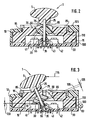
- FIG. 2 shows a side view of the mounted in the front panel operating element in a starting position
- Figure 3 is a side view of a mounted in the front panel operating element in a pivoted position.
- 5 denotes an actuating knob of a multifunctional operating element 1 designed in the form of a joystick.
- the multifunctional operating element 1 is held and guided by a guide piece 15 fixedly connected to a front panel 10.
- the guide piece 15 protrudes according to Figure 2 or Figure 3 in a first opening 95 on a user interface 105 of the front panel 10 from the inside of the front panel 10.
- the guide piece 15 four mutually perpendicular guide slots, which together form a cross-shaped slot.
- a first guide slot 51 and a second guide slot 52 are shown in Figure 1 for reasons of perspective view.
- the guide piece 15 is formed on a segment 5 facing the actuating button 5 spherical segment.
- the guide piece 15 can be covered by a cover plate 85 which can be plugged into the first opening 95, wherein the cover plate 85 can be opaque and has a recess 91, 92, 93, 94 in the region of the guide slots.
- the operating element 1 can be guided by means of the actuating button 5 in the guide slots of the guide piece 15, wherein a user the possible operating directions of the operating element 1 through the recesses 91, 92, 93, 94, which together enlarge the cross shape of the guide slots in the region of the user interface 105, be identified.
- the associated actuating direction can still be illustrated by one or more applied arrowheads.
- the front panel 10 is mounted on a printed circuit board 30 and laterally has a second opening 100, via which the guide piece 15 can be illuminated via a light source 80 according to FIG.
- the guide piece 15 As a light guide, this leads to a corresponding illumination of the recesses 91, 92, 93, 94 of the cover plate 85 recessed surfaces of the guide piece 15, so that the user the possible operating directions are made even in the dark.
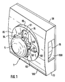
- FIG. 1 shows the operating element 1 in a starting position.
- the starting position is characterized in that the operating element 1 is not pivoted in one of the four possible directions of actuation and is located in the center of the cross formed by the guide slots.
- the mounted in the front panel 10 control element 1 is shown in a side view, wherein it is also in the starting position.
- the operating knob 5 is attached to an axis 25 and beveled on a guide piece 15 facing side 75 and about the axis 25 around.
- the operating element 1 has on a side opposite the operating knob 5 side of the guide piece 15, a base plate 20, wherein the actuating button 5 and the base plate 20 are fixedly connected to each other via the axis 25.
- the guide piece 15 has a recess 65 on a side facing away from the actuating button 5.
- the base plate 20 is formed on a side facing the operating knob 5 side 70 spherical segment.
- the base plate 20 On a side facing away from the operating knob 5, the base plate 20 has a chamfer 110 extending annularly around the axis 25.
- the axis 25 is mounted on the actuating button 5 opposite side of the guide piece 15 in a bearing 35 of the circuit board 30. The distance between the bearing 35 and the base plate 20 should exceed a predetermined value.
- the axis 25 is guided in the guide slots of the guide piece 15, so that it comes depending on the direction of actuation upon actuation of the control element 1 to pivot the base plate 20 via the operating knob 5 in one of the four possible directions of actuation.
- Each actuation direction or each guide slot is assigned to a contact pair on the printed circuit board 30, which can be contacted by actuation of a pushbutton switch or electrically conductively connected to one another.
- a push-button switch is provided, which is depressed by a corresponding pivoting of the control element 1 from the base plate 20 for contacting.
- the required pivot angle for depressing the corresponding key switch depends on the distance between the bearing 35 and the base plate 20 and the bevel 110 of the Sokkelplatte 20.
- three push-buttons 41, 42, 43 are shown due to the lateral representation in Figure 2 and Figure 3 respectively.
- the key switches are also arranged on the circuit board 30.
- the axis 25 is encompassed by a return spring 55 which cooperates with the axis 25 so that a pivoted base plate 20 springs back to the starting position.
- control element 1 is shown in a different from its initial position, pivoted position.
- a lateral force introduction on the actuating button 5 is represented by an arrow marked with the reference numeral 115.
- the actuating knob 5 slides with its bevel on its side facing the guide piece 15 side 75 along the actuating button 5 facing, in the region of the guide slots ball segment shaped side 60 of the guide piece 15.
- the base plate 20 with its the operating knob 5 facing spherical segment-shaped side 70th guided within the recess 65 along the guide piece 15.
- the lateral introduction of force on the operating knob 5 leads to a pivot angle of the operating element 1, which leads to a depression of a first key switch 41 on the circuit board 30 through the base plate 20, wherein a switching stroke 120 is realized, which arranged for contacting the corresponding on the circuit board 30 Contact surface pair via a contact of the corresponding first key switch 41 leads. Due to the chamfer 110 of the Sokkelplatte 20 this lies on depression of the corresponding key switch area on its surface, so that no significant wear of the base plate 20 and the corresponding key switch takes place. In the illustrated in Figure 3 pivoted position of the control element 1, the return spring 55 is laterally compressed by a spring 125, which causes the required for the return of the control element 1 in its initial position restoring force.
- the return spring 55 also serves to compensate for tolerance variations in the dimensions of the guide slots and the base plate 20 and the guide piece 15 and its recess 65 in particular.
- the front panel 10 may be part of an operating front of a car radio. It can be done in the formation of the guide piece 15 as a light guide an integration of the guide piece 15 in a total light guide the front of the car radio.
- the operating knob 5 is attachable to the axis 25 and the cover plate 85 is inserted into the first opening 95 of the front panel 10, so that the operating knob 5 and the cover plate 85 can be replaced depending on individual needs and the taste of the user.
- the multifunctional operating element 1 can be used by means of the actuation of the four push-buttons for selecting operating functions, for example on an operating menu and / or for setting functional values of an operating function, such as the volume and the balance, in particular in a car radio. Due to the multifunctionality of the control element 1, the space for the otherwise required corresponding individual control elements can be saved on the front panel of such a device and increase the clarity for the user.
- the operating element 1 can be used with all electrical devices in which operating functions and / or function values of operating functions can be set.
Description
Die Erfindung geht von einem multifunktionalen Bedienelement nach der Gattung des Hauptanspruchs aus.The invention is based on a multifunctional control element according to the preamble of the main claim.
Aus der noch nicht vorveröffentlichten deutschen Patentanmeldung mit dem Aktenzeichen
Die
Die Auslegeschrift
Das erfindungsgemäße multifunktionale Bedienelement mit den Merkmalen des Hauptanspruchs hat demgegenüber den Vorteil, dass eine Lagerung auf der dem Betätigungsknopf gegenüberliegenden Seite des Führungsstücks vorgesehen ist, in der die Achse gelagert ist. Auf diese Weise ist keine senkrechte Druckbewegung des Bedienelementes möglich, so daß eine gleichzeitige Kontaktierung von mehr als einem Kontakt verhindert werden kann.The multifunctional operating element according to the invention with the features of the main claim has the advantage that a bearing on the opposite side of the actuating button of the guide piece is provided, in which the Axis is stored. In this way, no vertical pressure movement of the control element is possible, so that a simultaneous contacting of more than one contact can be prevented.
Ein weiterer Vorteil besteht darin, daß eine Rückstellfeder vorgesehen ist, die so mit der Achse zusammenwirkt, daß eine verschwenkte Sockelplatte in eine Ausgangsstellung zurückfedert. Auf diese Weise wird der Bedienkomfort für den Benutzer erhöht, da er das Bedienelement nicht selbst in seine Ausgangsstellung zurückbringen muß. Weiterhin wird verhindert, daß ein Kontakt bzw. Tastschalter zu lange betätigt und auf diese Weise eventuell ein ungewollter Funktionswert eingestellt wird.Another advantage is that a return spring is provided which cooperates with the axis so that a pivoted base plate springs back into an initial position. In this way, the ease of use for the user is increased because he does not have to return the control itself to its original position. Furthermore, it is prevented that a contact or push-button operated too long and possibly an unwanted function value is set in this way.
Durch die in den Unteransprüchen aufgeführten Maßnahmen sind vorteilhafte Weiterbildungen und Verbesserungen des im Hauptanspruch angegebenen Bedienelementes möglich.The measures listed in the dependent claims advantageous refinements and improvements of the main claim control are possible.
Ein besonderer Vorteil besteht darin, daß der Abstand zwischen der Lagerung und der Sockelplatte einen vorgegebenen Wert überschreitet. Auf diese Weise ist zur Kontaktierung eines Kontaktes mittels der Sockelplatte ein Mindestverschwenkwinkel des Bedienelementes erforderlich, so daß die Positionen des Bedienelementes zur Kontaktierung der einzelnen Kontakte eindeutig voneinander getrennt sind.A particular advantage is that the distance between the bearing and the base plate exceeds a predetermined value. In this way, a Mindestverschwenkwinkel the control element is required for contacting a contact by means of the base plate, so that the positions of the control element for contacting the individual contacts are clearly separated.
Besonders vorteilhaft ist es, daß auf der Leiterplatte Tastschalter angeordnet sind, durch deren Betätigung die Kontaktierung der Kontakte auf der Leiterplatte erfolgt und daß die Tastschalter durch Verschwenken der Sockelplatte betätigbar sind. Auf diese Weise ergibt sich bei der Betätigung eines solchen Tastschalters durch Verschwenken des Bedienelementes ein sog. Schaltknack, durch den der Benutzer über die erfolgreiche Betätigung des entsprechenden Tastschalters informiert wird. Somit wird der Bedienkomfort für den Benutzer erhöht.It is particularly advantageous that tact switches are arranged on the printed circuit board, by the actuation of which the contacting of the contacts takes place on the printed circuit board and that the key switches can be actuated by pivoting the base plate. In this way, results in the operation of such a key switch by pivoting the control element, a so-called. Schaltknack, by the user on the successful operation of the corresponding key switch is informed. Thus, the ease of use for the user is increased.
Ein weiterer Vorteil besteht darin, daß das Führungsstück für jeden Tastschalter einen Führungsschlitz aufweist, in dem die Achse des Bedienelementes führbar ist und daß die Führungsschlitze so im Führungsstück angeordnet sind, daß bei Verschwenken der Sockelplatte der jeweils zugehörige Tastschalter betätigbar ist. Auf diese Weise ist eine definierte und eindeutige Bewegung des Bedienelementes zur Betätigung jeweils eines Kontaktes bzw. Tastschalters möglich, so daß Fehlbedienungen seitens des Benutzers, die zu keiner Kontaktgabe führen, ausgeschlossen werden.Another advantage is that the guide piece for each key switch has a guide slot in which the axis of the control element is feasible and that the guide slots are arranged in the guide piece, that upon pivoting of the base plate of the respective associated key switch can be actuated. In this way, a defined and unambiguous movement of the operating element for actuating a respective contact or key switch is possible, so that incorrect operations on the part of the user, which lead to no contact, are excluded.
Ein weiterer Vorteil besteht darin, daß das Führungsstück im Bereich der Führungsschlitze auf einer dem Betätigungsknopf zugewandten Seite kugelsegmentförmig ausgebildet ist. Auf diese Weise wird eine Auflage für den Betätigungsknopf realisiert, die ebenso wie die Lagerung der Achse verhindert, daß das Bedienelement über den Betätigungsknopf zur Leiterplatte hin gedrückt werden kann und gleichzeitig mehrere Kontakte bzw. Tastschalter durch die Sockelplatte betätigt werden könnten.Another advantage is that the guide piece is formed in the region of the guide slots on a side facing the operating knob spherical segment. In this way, a support for the operating knob is realized, which prevents as well as the storage of the axis that the control element can be pressed on the operating button to the circuit board and at the same time several contacts or push-button could be operated by the base plate.
Ein weiterer Vorteil besteht darin, daß das Führungsstück auf einer dem Betätigungsknopf abgewandten Seite eine Ausnehmung aufweist und daß die Sockelplatte auf einer dem Betätigungsknopf zugewandten Seite kugelsegmentförmig ausgebildet ist. Auf diese Weise läßt sich die Sockelplatte in der Ausnehmung des Führungsstückes führen, so daß die Bedienung für den Benutzer weiter vereinfacht und der Bedienkomfort erhöht wird. Außerdem wird auf diese Weise eine stabilere Lagerung des Bedienelementes in der Frontplatte realisiert.Another advantage is that the guide piece on a side facing away from the actuating knob has a recess and that the base plate is formed on a side facing the operating knob spherical segment. In this way, the base plate can be guided in the recess of the guide piece, so that the operation further simplified for the user and the ease of use is increased. In addition, a more stable storage of the control element in the front panel is realized in this way.
Ein weiterer Vorteil besteht darin, daß der Betätigungsknopf auf die Achse aufgesteckt und an einer dem Führungsstück zugewandten Seite abgeschrägt ist. Auf diese Weise läßt sich der Betätigungsknopf auf einfache Weise auswechseln und ein individuell an die Bedürfnisse und den Geschmack des Benutzers angepaßte Betätigungsknopf auf die Achse aufstecken. Durch die Abschrägung ergibt sich der Vorteil, daß der Betätigungsknopf auch bei Verschwenken des Bedienelementes auf dem Führungsstück gleitend aufliegen kann, so daß die Verschwenkbewegung des Bedienelementes durch das Führungsstück unterstützt und somit der Bedienkomfort erhöht wird.Another advantage is that the operating knob is plugged onto the axis and beveled on a side facing the guide piece. In this way, the operating knob can be replaced in a simple manner and attach an individually adapted to the needs and tastes of the user operating knob on the axle. By chamfering there is the advantage that the operating knob can slide slidably on pivoting of the control element on the guide piece, so that the pivoting movement of the control element supported by the guide piece and thus the ease of use is increased.
Ein weiterer Vorteil besteht darin, daß das Führungsstück als Lichtleitkörper ausgebildet ist und daß eine Lichtquelle zur Beleuchtung des Führungstücks vorgesehen ist. Auf diese Weise wird die Bedienung des Bedienelementes bei Dunkelheit für den Benutzer vereinfacht.Another advantage is that the guide piece is designed as a light guide body and that a light source is provided for illuminating the guide piece. In this way, the operation of the control is simplified in the dark for the user.
Ein weiterer Vorteil besteht darin, daß das Führungsstück durch eine vorzugsweise aufsteckbare Deckelplatte abgedeckt ist, daß die Deckelplatte nicht im Bereich der Führungsschlitze jeweils eine Aussparung aufweist. Auf diese Weise wird der Bedienkomfort für den Benutzer weiter erhöht, da ihm die möglichen Betätigungsrichtungen des Bedienelementes durch die Aussparungen der Deckelplatte bereits angezeigt werden. Dies gilt auch bei Dunkelheit und Beleuchtung des Führungsstückes durch eine Lichtquelle, da die Deckelplatte lichtundurchlässig ausgebildet ist.Another advantage is that the guide piece is covered by a preferably attachable cover plate, that the cover plate does not have in the region of the guide slots in each case a recess. In this way, the ease of use for the user is further increased because the possible directions of actuation of the operating element through the recesses of the cover plate are already displayed. This also applies to darkness and illumination of the guide piece by a light source, since the cover plate is made opaque.
Ein weiterer Vorteil besteht darin, daß der Benutzer die Deckelplatte individuell nach seinen Bedürfnissen und seinem Geschmack wählen kann, da die Deckelplatte auf das Führungsstück aufsteckbar und somit auswechselbar ist.Another advantage is that the user can choose the cover plate individually according to his needs and his taste, since the cover plate is attachable to the guide piece and thus replaceable.
Ein Ausführungsbeispiel der Erfindung ist in den Zeichnungen dargestellt und in der nachfolgenden Beschreibung näher erläutert. Es zeigen Figur 1 eine Schrägansicht eines in einer Frontplatte gelagerten erfindungsgemäßen Bedienelementes, Figur 2 eine Seitenansicht des in der Frontplatte gelagerten Bedienelementes in einer Ausgangslage und Figur 3 eine Seitenansicht eines in der Frontplatte gelagerten Bedienelementes in einer verschwenkten Lage.An embodiment of the invention is illustrated in the drawings and explained in more detail in the following description. 2 shows a side view of the mounted in the front panel operating element in a starting position and Figure 3 is a side view of a mounted in the front panel operating element in a pivoted position.
In Figur 1 kennzeichnet 5 einen Betätigungsknopf eines in Form eines Joysticks ausgebildeten multifunktionalen Bedienelements 1. Das multifunktionale Bedienelement 1 ist von einem fest mit einer Frontplatte 10 verbundenen Führungsstück 15 gehalten und geführt. Das Führungsstück 15 ragt dabei gemäß Figur 2 bzw. Figur 3 in einer ersten Öffnung 95 an einer Bedienoberfläche 105 der Frontplatte 10 vom Inneren der Frontplatte 10 hervor. Dabei weist das Führungsstück 15 vier zueinander senkrecht benachbarte Führungsschlitze auf, die zusammen einen kreuzförmigen Schlitz bilden. Von den vier Führungsschlitzen sind in Figur 1 aus Gründen der perspektivischen Darstellung ein erster Führungsschlitz 51 und ein zweiter Führungsschlitz 52 dargestellt. Im Bereich der Führungsschlitze ist das Führungsstück 15 auf einer dem Betätigungsknopf 5 zugewandten Seite 60 kugelsegmentförmig ausgebildet. Dies wird ebenfalls in den Seitenansichten der Figuren 2 und 3 deutlich. Das Führungsstück 15 kann durch eine in die erste Öffnung 95 steckbare Deckelplatte 85 abgedeckt sein, wobei die Deckelplatte 85 lichtundurchlässig sein kann und im Bereich der Führungsschlitze jeweils eine Aussparung 91, 92, 93, 94 aufweist.In FIG. 1, 5 denotes an actuating knob of a multifunctional operating element 1 designed in the form of a joystick. The multifunctional operating element 1 is held and guided by a
Das Bedienelement 1 ist mittels dem Betätigungsknopf 5 in den Führungsschlitzen des Führungsstückes 15 führbar, wobei einem Benutzer die möglichen Betätigungsrichtungen des Bedienelementes 1 durch die Aussparungen 91, 92, 93, 94, die zusammen die Kreuzform der Führungsschlitze vergrößert im Bereich der Bedienoberfläche 105 abbilden, kenntlich gemacht werden. Dabei kann in Verlängerung der Führungsschlitze auf dem Führungsstück 15 innerhalb der Aussparungen 91, 92, 93, 94 jeweils die zugehörige Betätigungsrichtung noch durch eine oder mehrere aufgebrachte Pfeilspitzen verdeutlicht werden. Die Frontplatte 10 ist auf einer Leiterplatte 30 aufgebracht und weist seitlich eine zweite Öffnung 100 auf, über die das Führungsstück 15 über eine Lichtquelle 80 gemäß Figur 3 beleuchtet werden kann. Bei Ausbildung des Führungsstückes 15 als Lichtleitkörper führt dies zu einer entsprechenden Beleuchtung der durch die Aussparungen 91, 92, 93, 94 der Deckelplatte 85 ausgesparten Flächen des Führungsstückes 15, so daß dem Benutzer die möglichen Betätigungsrichtungen auch bei Dunkelheit kenntlich gemacht werden.The operating element 1 can be guided by means of the actuating
Figur 1 zeigt das Bedienelement 1 in einer Ausgangsstellung. Die Ausgangsstellung ist dadurch gekennzeichnet, daß das Bedienelement 1 nicht in eine der vier möglichen Betätigungsrichtungen verschwenkt ist und sich im Zentrum des durch die Führungsschlitze gebildeten Kreuzes befindet.FIG. 1 shows the operating element 1 in a starting position. The starting position is characterized in that the operating element 1 is not pivoted in one of the four possible directions of actuation and is located in the center of the cross formed by the guide slots.
In Figur 2 ist das in der Frontplatte 10 gelagerte Bedienelement 1 in einer Seitenansicht dargestellt, wobei es sich ebenfalls in der Ausgangsstellung befindet. Der Betätigungsknopf 5 ist dabei auf eine Achse 25 aufgesteckt und an einer dem Führungsstück 15 zugewandten Seite 75 und um die Achse 25 herum abgeschrägt. Das Bedienelement 1 weist auf einer dem Betätigungsknopf 5 gegenüberliegenden Seite des Führungsstücks 15 eine Sockelplatte 20 auf, wobei der Betätigungsknopf 5 und die Sockelplatte 20 über die Achse 25 miteinander fest verbunden sind. Das Führungsstück 15 weist auf einer dem Betätigungsknopf 5 abgewandten Seite eine Ausnehmung 65 auf. Die Sockelplatte 20 ist auf einer dem Betätigungsknopf 5 zugewandten Seite 70 kugelsegmentförmig ausgebildet. Auf einer dem Betätigungsknopf 5 abgewandten Seite weist die Sockelplatte 20 ringförmig um die Achse 25 herum verlaufend eine Abschrägung 110 auf. Die Achse 25 ist auf der dem Betätigungsknopf 5 gegenüberliegenden Seite des Führungsstücks 15 in einer Lagerung 35 der Leiterplatte 30 gelagert. Der Abstand zwischen der Lagerung 35 und der Sockelplatte 20 soll dabei einen vorgegebenen Wert überschreiten.In Figure 2, the mounted in the
Die Achse 25 ist in den Führungsschlitzen des Führungsstücks 15 geführt, so daß es je nach Betätigungsrichtung bei der Betätigung des Bedienelementes 1 zu einem Verschwenken der Sockelplatte 20 über den Betätigungsknopf 5 in eine der vier möglichen Betätigungsrichtungen kommt. Jede Betätigungsrichtung bzw. jeder Führungsschlitz ist dabei auf der Leiterplatte 30 einem Kontaktpaar zugeordnet, das durch Betätigung eines Tastschalters kontaktiert bzw. elektrisch leitend miteinander verbunden werden kann. Für jede Betätigungsrichtung ist also ein Tastschalter vorgesehen, der bei entsprechendem Verschwenken des Bedienelementes 1 von der Sockelplatte 20 zur Kontaktierung niedergedrückt wird. Dabei hängt der erforderliche Verschwenkwinkel zum Niederdrücken des entsprechenden Tastschalters vom Abstand zwischen der Lagerung 35 und der Sockelplatte 20 sowie der Abschrägung 110 der Sokkelplatte 20 ab. Von den vier Tastschaltern sind aufgrund der seitlichen Darstellung in Figur 2 und Figur 3 jeweils drei Tastschalter 41, 42, 43 dargestellt.The
Die Tastschalter sind dabei ebenfalls auf der Leiterplatte 30 angeordnet. Bei Verschwenken der Sockelplatte 20 über den Betätigungsknopf 5 und die im entsprechenden Führungsschlitz geführte Achse 25 ist somit der jeweils zugehörige Tastschalter betätigbar. Zwischen der Sockelplatte 20 und der Lagerung 35 wird die Achse 25 von einer Rückstellfeder 55 umgriffen, die so mit der Achse 25 zusammenwirkt, daß eine verschwenkte Sockelplatte 20 in die Ausgangsstellung zurückfedert.The key switches are also arranged on the
In Figur 3 ist das Bedienelement 1 in einer von seiner Ausgangslage verschiedenen, verschwenkten Lage dargestellt. Dabei wird durch einen mit dem Bezugszeichen 115 gekennzeichneten Pfeil eine seitliche Krafteinleitung am Betätigungsknopf 5 dargestellt. Der Betätigungsknopf 5 gleitet dabei mit seiner Abschrägung an seiner dem Führungsstück 15 zugewandten Seite 75 entlang der dem Betätigungsknopf 5 zugewandten, im Bereich der Führungsschlitze kugelsegmentförmig ausgebildeten Seite 60 des Führungsstückes 15. Gleichzeitig ist die Sockelplatte 20 mit ihrer dem Betätigungsknopf 5 zugewandten kugelsegmentförmig ausgebildeten Seite 70 innerhalb der Ausnehmung 65 entlang dem Führungsstück 15 geführt. Dabei führt die seitliche Krafteinleitung am Betätigungsknopf 5 zu einem Verschwenkwinkel des Bedienelementes 1, der zu einem Niederdrücken eines ersten Tastschalters 41 auf der Leiterplatte 30 durch die Sockelplatte 20 führt, wobei ein Schalthub 120 realisiert wird, der zur Kontaktierung des entsprechenden auf der Leiterplatte 30 angeordneten Kontaktflächenpaares über einen Kontakt des entsprechenden ersten Tastschalters 41 führt. Durch die Abschrägung 110 der Sokkelplatte 20 liegt diese beim Niederdrücken des entsprechenden Tastschalters flächig auf dessen Oberfläche auf, so daß keine wesentliche Abnutzung der Sockelplatte 20 und des entsprechenden Tastschalters erfolgt. In der in Figur 3 dargestellten verschwenkten Lage des Bedienelementes 1 ist die Rückstellfeder 55 um einen Federweg 125 seitlich zusammengedrückt, der die für die Rückführung des Bedienelementes 1 in seine Ausgangsstellung erforderliche Rückstellkraft bewirkt.In Figure 3, the control element 1 is shown in a different from its initial position, pivoted position. In this case, a lateral force introduction on the
Die Rückstellfeder 55 dient weiterhin dazu, Toleranzschwankungen bei den Abmessungen insbesondere der Führungsschlitze und der Sockelplatte 20 sowie dem Führungsstück 15 und seiner Ausnehmung 65 auszugleichen.The
Die Frontplatte 10 kann Teil eine Bedienfront eines Autoradios sein. Dabei kann bei Ausbildung des Führungsstückes 15 als Lichtleitkörper eine Integration des Führungsstücks 15 in einen Gesamtlichtleiter der Bedienfront des Autoradios erfolgen. Der Betätigungsknopf 5 ist auf die Achse 25 aufsteckbar und die Deckelplatte 85 ist in die erste Öffnung 95 der Frontplatte 10 einsteckbar, so daß der Betätigungsknopf 5 und die Deckelplatte 85 je nach individuellen Bedürfnissen und dem Geschmack des Benutzers ausgewechselt werden können.The
Das multifunktionale Bedienelement 1 kann mittels der Betätigung der vier Tastschalter zur Auswahl von Bedienfunktionen, beispielsweise an einem Bedienmenü und/oder zur Einstellung von Funktionswerten einer Bedienfunktion, wie beispielsweise der Lautstärke und der Balance insbesondere bei einem Autoradio verwendet werden. Durch die Multifunktionalität des Bedienelementes 1 läßt sich an der Bedienfront eines solchen Gerätes der Platz für die ansonsten erforderlichen entsprechenden Einzelbedienelemente einsparen und die Übersichtlichkeit für den Benutzer erhöhen.The multifunctional operating element 1 can be used by means of the actuation of the four push-buttons for selecting operating functions, for example on an operating menu and / or for setting functional values of an operating function, such as the volume and the balance, in particular in a car radio. Due to the multifunctionality of the control element 1, the space for the otherwise required corresponding individual control elements can be saved on the front panel of such a device and increase the clarity for the user.
Es können auch mehr oder weniger als vier Betätigungsrichtungen und zugehörige Tastschalter vorgesehen sein, je nach Anforderungen an die durch das Bedienelement 1 zu realisierende Multifunktionalität.It is also possible to provide more or fewer than four actuation directions and associated push-button switches, depending on the requirements of the multifunctionality to be realized by the operating element 1.
Das Bedienelement 1 ist bei allen elektrischen Geräten einsetzbar, bei denen Bedienfunktionen und/oder Funktionswerte von Bedienfunktionen eingestellt werden können.The operating element 1 can be used with all electrical devices in which operating functions and / or function values of operating functions can be set.
Claims (10)
- Multifunctional operator control (1) having an activation knob (5) which is held and guided by a guide piece (15) connected to a front panel (10), and has a base plate (20) on a side of the guide piece (15) lying opposite the activation knob (5), wherein the activation knob (5) and the base plate (20) are connected to one another by means of a shaft (25), wherein contact is formed between contact elements which are arranged on a printed circuit board (30) by pivoting the base plate (20) by means of the activation knob (5), and wherein a bearing (35) is provided on the side of the guide piece (15) lying opposite the activation knob (5), in which bearing (35) the shaft (25) is mounted, characterized in that a restoring spring (55) is provided which engages around the shaft (25) and interacts with the shaft (25) in such a way that a pivoted base plate (20) springs back into a home position.
- Operator control according to Claim 1, characterized in that the base plate (20) is removably mounted on the shaft (25) and is pressed against the guide piece (15) by the restoring spring (55).
- Operator control according to one of the preceding claims, characterized in that the distance between the bearing (35) and the base plate (20) exceeds a predefinable value.
- Operator control (1) according to one of the preceding claims, characterized in that momentary contact switches (41, 42, 43), whose activation causes contact to be made with the contact elements on the printed circuit board (30), are arranged on the printed circuit board (30), and in that the momentary contact switches (41, 42, 43) can be activated by pivoting the base plate (20).
- Operator control (1) according to one of the preceding claims, characterized in that the guide piece (15) has, for each momentary contact switch (41, 42, 43), a guide slot (51, 52) in which the shaft (25) of the operator control (1) can be guided, and in that the guide slots (51, 52) are arranged in the guide piece (15) in such a way that when the base plate (20) is pivoted the respectively associated momentary contact switch (41, 42, 43) can be activated.
- Operator control (1) according to Claim 5, characterized in that the guide piece (15) is embodied in the form of a spherical segment on a side (60) facing the activation knob (5) in the region of the guide slots (51, 52) in order to form a support for the activation knob (5).
- Operator control (1) according to one of the preceding claims, characterized in that the guide piece (15) has a cut-out (65) on a side facing away from the activation knob (5), and in that the base plate (20) is embodied in the form of a spherical segment on a side (70) facing the activation knob (5).
- Operator control (1) according to one of the preceding claims, characterized in that the activation knob (5) is plugged onto the shaft (25) and is bevelled at a side (75) facing the guide piece (15).
- Operator control (1) according to one of the preceding claims, characterized in that the guide piece (15) is embodied as a light guide element, and in that a light source (8.0) is provided for illuminating the guide piece (15).
- Operator control (1) according to one of Claims 5-9, characterized in that the guide piece (15) is covered by a preferably plug-on cover plate (85), in that the cover plate (85) is non-translucent and in that the cover plate (85) has a cut-out (91, 92, 93, 94) in the region of each of the guide slots (51, 52).
Priority Applications (1)
| Application Number | Priority Date | Filing Date | Title |
|---|---|---|---|
| EP07123877A EP1912106B1 (en) | 1997-09-20 | 1998-03-28 | Multifunctional operating element |
Applications Claiming Priority (2)
| Application Number | Priority Date | Filing Date | Title |
|---|---|---|---|
| DE19741560 | 1997-09-20 | ||
| DE1997141560 DE19741560A1 (en) | 1997-09-20 | 1997-09-20 | Multifunctional control element |
Related Child Applications (1)
| Application Number | Title | Priority Date | Filing Date |
|---|---|---|---|
| EP07123877A Division EP1912106B1 (en) | 1997-09-20 | 1998-03-28 | Multifunctional operating element |
Publications (3)
| Publication Number | Publication Date |
|---|---|
| EP0903658A2 EP0903658A2 (en) | 1999-03-24 |
| EP0903658A3 EP0903658A3 (en) | 2003-05-14 |
| EP0903658B1 true EP0903658B1 (en) | 2008-01-09 |
Family
ID=7843072
Family Applications (2)
| Application Number | Title | Priority Date | Filing Date |
|---|---|---|---|
| EP07123877A Expired - Lifetime EP1912106B1 (en) | 1997-09-20 | 1998-03-28 | Multifunctional operating element |
| EP19980105702 Expired - Lifetime EP0903658B1 (en) | 1997-09-20 | 1998-03-28 | Multifunctional joystick |
Family Applications Before (1)
| Application Number | Title | Priority Date | Filing Date |
|---|---|---|---|
| EP07123877A Expired - Lifetime EP1912106B1 (en) | 1997-09-20 | 1998-03-28 | Multifunctional operating element |
Country Status (4)
| Country | Link |
|---|---|
| EP (2) | EP1912106B1 (en) |
| JP (1) | JPH11162299A (en) |
| DE (3) | DE19741560A1 (en) |
| ES (2) | ES2296319T3 (en) |
Families Citing this family (5)
| Publication number | Priority date | Publication date | Assignee | Title |
|---|---|---|---|---|
| DE10013630C2 (en) * | 2000-03-18 | 2002-10-31 | Kostal Leopold Gmbh & Co Kg | Electrical switch |
| DE10022612C2 (en) * | 2000-05-09 | 2002-06-27 | Kostal Leopold Gmbh & Co Kg | switching element |
| DE10042028B4 (en) * | 2000-08-26 | 2006-07-27 | Audi Ag | Multifunctional operating device |
| DE10160389A1 (en) * | 2000-12-13 | 2002-08-14 | Marquardt Gmbh | Joystick or cursor type switch for data entry in a motor vehicle electrical device, has switch control curve is such that incorrect operation is made extremely unlikely |
| JP2006286331A (en) | 2005-03-31 | 2006-10-19 | Alps Electric Co Ltd | Multiple direction input device |
Family Cites Families (6)
| Publication number | Priority date | Publication date | Assignee | Title |
|---|---|---|---|---|
| GB379897A (en) * | 1931-10-19 | 1932-09-08 | Edward Vernon Anson Willett | Improvements in and relating to multi-position electric switches |
| GB709917A (en) * | 1951-01-08 | 1954-06-02 | Trico Folberth Ltd | Improvements relating to electric switches |
| US3156134A (en) * | 1961-07-25 | 1964-11-10 | Ritter Co Inc | Control apparatus for dental chair |
| DE1268251B (en) * | 1966-07-09 | 1968-05-16 | Siemens Ag | Switching device with a pivoting switch rod |
| US4408103A (en) * | 1982-01-06 | 1983-10-04 | Smith Engineering | Joystick operated multiple position switch |
| DE19722369B4 (en) | 1997-05-28 | 2009-06-10 | Robert Bosch Gmbh | Operating front of a car radio and a car radio with it |
-
1997
- 1997-09-20 DE DE1997141560 patent/DE19741560A1/en not_active Withdrawn
-
1998
- 1998-03-28 ES ES98105702T patent/ES2296319T3/en not_active Expired - Lifetime
- 1998-03-28 ES ES07123877T patent/ES2331211T3/en not_active Expired - Lifetime
- 1998-03-28 DE DE59814399T patent/DE59814399D1/en not_active Expired - Lifetime
- 1998-03-28 EP EP07123877A patent/EP1912106B1/en not_active Expired - Lifetime
- 1998-03-28 EP EP19980105702 patent/EP0903658B1/en not_active Expired - Lifetime
- 1998-03-28 DE DE59814150T patent/DE59814150D1/en not_active Expired - Lifetime
- 1998-09-18 JP JP26493098A patent/JPH11162299A/en active Pending
Also Published As
| Publication number | Publication date |
|---|---|
| EP1912106B1 (en) | 2009-09-30 |
| EP0903658A3 (en) | 2003-05-14 |
| DE59814399D1 (en) | 2009-11-12 |
| JPH11162299A (en) | 1999-06-18 |
| ES2331211T3 (en) | 2009-12-23 |
| DE19741560A1 (en) | 1999-03-25 |
| DE59814150D1 (en) | 2008-02-21 |
| ES2296319T3 (en) | 2008-04-16 |
| EP1912106A1 (en) | 2008-04-16 |
| EP0903658A2 (en) | 1999-03-24 |
Similar Documents
| Publication | Publication Date | Title |
|---|---|---|
| DE19600657C1 (en) | Multi-stage electric rocker-action switch e.g. for automobile | |
| EP1907916B1 (en) | Operating element with a central pushbutton | |
| EP0295437A2 (en) | Push-button device | |
| EP1860916A2 (en) | Hearing aid with a flip switch for turning on/off | |
| DE2337904C2 (en) | Push button switch | |
| DE102005053931A1 (en) | switch device | |
| DE2918640A1 (en) | PUSH BUTTON SWITCH | |
| DE19726149A1 (en) | Switch arrangement | |
| EP0903658B1 (en) | Multifunctional joystick | |
| EP3939062B1 (en) | Electrical installation device | |
| EP0301413B1 (en) | Electrical switch, especially for motor vehicles | |
| DE2904900C2 (en) | Electric switch | |
| DE19619124B4 (en) | Toggle switch, in particular for window regulators in a motor vehicle | |
| EP1702796B1 (en) | Combined push button and rotary switch for a vehicle | |
| DE3818810A1 (en) | Electrical tumbler switch with several unstable rocker positions | |
| EP0643408A1 (en) | Push button switch | |
| DE19836793C2 (en) | Control element for the selective establishment of electrical contacts | |
| DE3532740A1 (en) | SLIDING ELECTRICAL COMPONENT, ESPECIALLY FOR SLIDE SWITCHES | |
| EP0817446A2 (en) | Switching device for telephone sets | |
| DE3018810C2 (en) | ||
| DE2931370A1 (en) | Double action multicontact tumbler switch - has first bridging leaf spring depressed onto second springs under first and further pressure | |
| DE102007017889B4 (en) | operating element | |
| DE4210602C2 (en) | Push button operated rocker switch or button for electrical house installations | |
| EP0450319B1 (en) | Push-button switch | |
| EP1744335B1 (en) | Switchgear for electrical home installation |
Legal Events
| Date | Code | Title | Description |
|---|---|---|---|
| PUAI | Public reference made under article 153(3) epc to a published international application that has entered the european phase |
Free format text: ORIGINAL CODE: 0009012 |
|
| AK | Designated contracting states |
Kind code of ref document: A2 Designated state(s): AT BE CH DE DK ES FI FR GB GR IE IT LI LU MC NL PT SE |
|
| AX | Request for extension of the european patent |
Free format text: AL;LT;LV;MK;RO;SI |
|
| PUAL | Search report despatched |
Free format text: ORIGINAL CODE: 0009013 |
|
| AK | Designated contracting states |
Designated state(s): AT BE CH DE DK ES FI FR GB GR IE IT LI LU MC NL PT SE |
|
| AX | Request for extension of the european patent |
Extension state: AL LT LV MK RO SI |
|
| 17P | Request for examination filed |
Effective date: 20031114 |
|
| AKX | Designation fees paid |
Designated state(s): DE ES FR GB IT |
|
| 17Q | First examination report despatched |
Effective date: 20050712 |
|
| GRAP | Despatch of communication of intention to grant a patent |
Free format text: ORIGINAL CODE: EPIDOSNIGR1 |
|
| GRAS | Grant fee paid |
Free format text: ORIGINAL CODE: EPIDOSNIGR3 |
|
| GRAA | (expected) grant |
Free format text: ORIGINAL CODE: 0009210 |
|
| AK | Designated contracting states |
Kind code of ref document: B1 Designated state(s): DE ES FR GB IT |
|
| REG | Reference to a national code |
Ref country code: GB Ref legal event code: FG4D Free format text: NOT ENGLISH |
|
| REF | Corresponds to: |
Ref document number: 59814150 Country of ref document: DE Date of ref document: 20080221 Kind code of ref document: P |
|
| REG | Reference to a national code |
Ref country code: ES Ref legal event code: FG2A Ref document number: 2296319 Country of ref document: ES Kind code of ref document: T3 |
|
| GBT | Gb: translation of ep patent filed (gb section 77(6)(a)/1977) |
Effective date: 20080418 |
|
| ET | Fr: translation filed | ||
| PLBE | No opposition filed within time limit |
Free format text: ORIGINAL CODE: 0009261 |
|
| STAA | Information on the status of an ep patent application or granted ep patent |
Free format text: STATUS: NO OPPOSITION FILED WITHIN TIME LIMIT |
|
| 26N | No opposition filed |
Effective date: 20081010 |
|
| PGFP | Annual fee paid to national office [announced via postgrant information from national office to epo] |
Ref country code: ES Payment date: 20110324 Year of fee payment: 14 Ref country code: GB Payment date: 20110324 Year of fee payment: 14 |
|
| PGFP | Annual fee paid to national office [announced via postgrant information from national office to epo] |
Ref country code: IT Payment date: 20120327 Year of fee payment: 15 |
|
| GBPC | Gb: european patent ceased through non-payment of renewal fee |
Effective date: 20120328 |
|
| PG25 | Lapsed in a contracting state [announced via postgrant information from national office to epo] |
Ref country code: GB Free format text: LAPSE BECAUSE OF NON-PAYMENT OF DUE FEES Effective date: 20120328 |
|
| PGFP | Annual fee paid to national office [announced via postgrant information from national office to epo] |
Ref country code: FR Payment date: 20130329 Year of fee payment: 16 |
|
| REG | Reference to a national code |
Ref country code: ES Ref legal event code: FD2A Effective date: 20130710 |
|
| PG25 | Lapsed in a contracting state [announced via postgrant information from national office to epo] |
Ref country code: ES Free format text: LAPSE BECAUSE OF NON-PAYMENT OF DUE FEES Effective date: 20120329 |
|
| PGFP | Annual fee paid to national office [announced via postgrant information from national office to epo] |
Ref country code: DE Payment date: 20130523 Year of fee payment: 16 |
|
| REG | Reference to a national code |
Ref country code: DE Ref legal event code: R119 Ref document number: 59814150 Country of ref document: DE |
|
| REG | Reference to a national code |
Ref country code: FR Ref legal event code: ST Effective date: 20141128 |
|
| REG | Reference to a national code |
Ref country code: DE Ref legal event code: R119 Ref document number: 59814150 Country of ref document: DE Effective date: 20141001 |
|
| PG25 | Lapsed in a contracting state [announced via postgrant information from national office to epo] |
Ref country code: FR Free format text: LAPSE BECAUSE OF NON-PAYMENT OF DUE FEES Effective date: 20140331 Ref country code: DE Free format text: LAPSE BECAUSE OF NON-PAYMENT OF DUE FEES Effective date: 20141001 |
|
| PG25 | Lapsed in a contracting state [announced via postgrant information from national office to epo] |
Ref country code: IT Free format text: LAPSE BECAUSE OF NON-PAYMENT OF DUE FEES Effective date: 20140328 |