EP0903652A2 - Bedien- und Beobachtungsvorrichtung mit Infrarotsende- und Empfangseinrichtung - Google Patents
Bedien- und Beobachtungsvorrichtung mit Infrarotsende- und Empfangseinrichtung Download PDFInfo
- Publication number
- EP0903652A2 EP0903652A2 EP98107998A EP98107998A EP0903652A2 EP 0903652 A2 EP0903652 A2 EP 0903652A2 EP 98107998 A EP98107998 A EP 98107998A EP 98107998 A EP98107998 A EP 98107998A EP 0903652 A2 EP0903652 A2 EP 0903652A2
- Authority
- EP
- European Patent Office
- Prior art keywords
- operating
- infrared
- display
- control
- data transmission
- Prior art date
- Legal status (The legal status is an assumption and is not a legal conclusion. Google has not performed a legal analysis and makes no representation as to the accuracy of the status listed.)
- Withdrawn
Links
Images
Classifications
-
- H—ELECTRICITY
- H02—GENERATION; CONVERSION OR DISTRIBUTION OF ELECTRIC POWER
- H02B—BOARDS, SUBSTATIONS OR SWITCHING ARRANGEMENTS FOR THE SUPPLY OR DISTRIBUTION OF ELECTRIC POWER
- H02B15/00—Supervisory desks or panels for centralised control or display
Definitions
- operating and monitoring devices such as so-called 'operator panels' or so-called 'touch panels'
- the operating and monitoring devices in particular as installation devices of this type in a housing can be installed sealed so that it protects against external environmental influences, such as splash water, greases and dusts are protected.
- the control panel usually has input and display devices, which through appropriate measures for industrial use are designed. Examples are the keyboard and display covered by a protective film or the operating and Observation device has a transparent front Front window with built-in membrane keyboard.
- the device electronics the operating and monitoring device, which in particular at least for controlling the display and input device is usually behind the front, arranged protected lying inside the housing.
- an operating and monitoring device electronic interfaces through which in particular operated and externally arranged electronic circuit is observed, for example around an external technical Control process.
- the electronic interfaces and thus also the plug and cable connections of the operating and Observation device are also behind the Front arranged, protected inside the housing, in that the control and monitoring device is installed.
- this is necessary for security reasons and on the other hand, necessary to make the plug connections opposite the Process environment, such as splash water, dust and / or To protect greases.
- Such operating and monitoring devices are, for example from the Siemens catalog 'The SIMATIC HMI program, Operation and monitoring for every requirement ', status 10/01/96, known.
- the housing for example a control panel or cabinet, in which the operating and monitoring device is installed, can be opened constructed.
- the housing can be opened, so that the connector of the control and monitoring device for accessible to the operator for connecting cable connections become.
- the housing in which the operating and monitoring device is installed must be designed foldable, and on the other hand during a Data transmission with an external transmitter and receiver the housing must remain open, which Protection against environmental influences and possibly even the operation of the control and monitoring device considerably is affected. Furthermore, it is disadvantageous that the Preparations for a data transfer between the operating and Observation device and an external transmission and Receiving device are cumbersome and time consuming since it is necessary to first open the housing and, for example Data cable to the plug elements of the control and monitoring device to be stuck.
- the object of the invention is therefore an operating and monitoring device indicate which it is on a simpler Way allows data transfer with an external Transmit / receive device.
- the advantage of the invention is that an infrared transmission and / or reception device for data transmission is additionally arranged on the front of the operating and monitoring device is.
- the data transmission is preferably carried out with at least an external transmitting and / or receiving device.
- a data transmission via can also be advantageous during normal operation of the operating and monitoring device the infrared transmission and / or reception device take place.
- the operating and monitoring device can be fixed and remain sealed in the housing, or the housing does not need to be opened for data transmission.
- a data transfer can therefore be done without interfering with the existing System construction and without impairing normal operation respectively.
- the infrared transmission and / or reception device a bundled Beam angle on, resulting in a high, low-error data transfer rate and security against eavesdropping is increased.
- a translucent light and infrared Protective film for covering arranged by the display and / or input device and the infrared transmission and / or reception device.
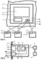
- FIG. 1 shows an example of a front view of an inventive one Control and monitoring device B for a technical shown symbolically in Figure 2 Process P shown in the state installed in a housing G.
- the housing G is, for example, a control cabinet or a Control panel.
- On a front F of the control and monitoring device B is at least one display device A and / or an input device T is arranged.
- a display device A is, for example, a liquid crystal display
- an input device T is, for example Keyboard.
- the functions of the display device and input device A or T can in particular also in one touch-sensitive display / input device, in particular merged into a so-called 'touchscreen' be.
- the control and monitoring device B additionally an infrared transmission and / or -Receiving device arranged for data transmission.
- FIG 1 shows the infrared transmission and / or reception device IR, for example, an infrared transmitter IRA and an infrared receiver IRE. These are for example an infrared transmitting or an infrared receiving diode.
- the via the infrared transmission and / or reception device IR data transmission which in the Figure 1 symbolized as an example with the arrows D1 to Dn is preferably done with at least one external transmit and Receiving device P1 to PN, each of which has its own infrared transmitting and / or receiving devices IR1 to IRn.
- the data transmission D1 to Dn is preferably serial and especially bidirectional.
- the external broadcast and Receiving device P1 to PN is, for example, a portable one Computer, notebook, modem or printer.
- FIG. 2 shows an example of a sectional side view the operating and monitoring device according to the invention B shown in the installed state in the housing G.
- the operating and monitoring processes take place thereby from the front F.
- the operating and monitoring device B an electronic circuit E with an electronic SI interface for controlling the infrared transmission and / or receiving device IR.
- the control of the Infrared transmission and / or reception device IR by the Electronic interface SI is an example in FIG. 2 represented by the arrow K2.
- the electronic circuit E also serves in particular to control the in the display and / or input device shown in FIG A and T, the functions of which are shown in FIG. 2 as examples the reference symbol TS, for example a so-called 'touchscreen', are summarized.
- the electronic circuit E for example, processes, prepares or saves in particular Process data DA of the technical process P, which according to the invention via the infrared transmission and / or reception device IR can be transmitted.
- the electronic Interface SI can also be used, for example, as in Housing G arranged, wired interface K1 for a process control C and the technical process P serve.
- the infrared transmission and / or reception device IR has the infrared transmission and / or reception device IR a bundled beam angle IRW, which in particular is less than or equal to 30 degrees.
- IRW a bundled beam angle
- the data transmission takes place, for example, by means of a standardized so-called 'RZI protocol', which by the Infrared Data Association for infrared data transmission is set.
- the operating and monitoring device B has one on the Front F arranged light and infrared transparent cover film SC, especially a cover plate. This covers the display and / or input device A or T and the infrared transmitting and / or receiving device IR for Protection against external environmental influences.
Landscapes
- Engineering & Computer Science (AREA)
- Power Engineering (AREA)
- Selective Calling Equipment (AREA)
- Geophysics And Detection Of Objects (AREA)
- Measuring And Recording Apparatus For Diagnosis (AREA)
Abstract
Description
- FIG 1
- beispielhaft eine Frontansicht auf die erfindungsgemäße Bedien- und Beobachtungsvorrichtung im in ein Gehäuse eingebauten Zustand, wobei über die Infrarotsende- und/oder -Empfangseinrichtung eine Datenübertragung mit externen Sende- und Empfangseinrichtungen erfolgt,
- FIG 2
- beispielhaft eine seitliche Schnittdarstellung der erfindungsgemäßen Bedien- und Beobachtungsvorrichtung im eingebauten Zustand mit elektronischer Schnittstelle zur Ansteuerung der Infrarotsende- und/oder - Empfangseinrichtung.
Claims (7)
- Bedien- und Beobachtungsvorrichtung (B) für einen technischen Prozeß (P), mit einer Frontseite (F, SC), an der wenigstens eine Anzeige- und/oder Eingabeeinrichtung (A, T, TS) angeordnet ist dadurch gekennzeichnet, daß an der Frontseite (F) zusätzlich eine Infrarotsende- und/oder -empfangseinrichtung (IR) zur Datenübertragung (D1..Dn) angeordnet ist, insbesondere zur Datenübertragung von Prozeßdaten (DA) des technischen Prozesses (P).
- Bedien- und Beobachtungsvorrichtung (B) nach Anspruch 1, gekennzeichnet durch eine elektronische Schaltung (E) mit einer elektronischen Schnittstelle (SI) zur Ansteuerung (K2) der Infrarotsende- und/oder -empfangseinrichtung (IR).
- Bedien- und Beobachtungsvorrichtung (B) nach einem der vorangegangenen Ansprüche, dadurch gekennzeichnet, daß die Infrarotsende- und/oder -empfangseinrichtung (IR) einen gebündelten Abstrahlwinkel (IRW), insbesondere kleiner gleich 30 Grad, aufweist.
- Bedien- und Beobachtungsvorrichtung (B) nach einem der vorangegangenen Ansprüche, gekennzeichnet durch eine an der Frontseite (F) angeordnete licht- und infrarotlichtdurchlässige Schutzfolie (SC) zur Abdeckung der Anzeige- und/oder Eingabeeinrichtung (A, T, TS) und der Infrarotsende- und/oder -empfangseinrichtung (IR).
- Bedien- und Beobachtungsvorrichtung (B) nach einem der vorangegangenen Ansprüche, dadurch gekennzeichnet, daß die Eingabeeinrichtung (T) eine Tastatur ist.
- Bedien- und Beobachtungsvorrichtung (B) nach einem der vorangegangenen Ansprüche, dadurch gekennzeichnet, daß die Ausgabeeinrichtung (A) eine elektronische Anzeige, insbesondere ein Flüssigkristallbildschirm ist.
- Bedien- und Beobachtungsvorrichtung (B) nach einem der Ansprüche 1 bis 4, dadurch gekennzeichnet, daß die Anzeige- und/oder die Eingabeeinrichtung (A, E) eine berührungsempfindliche Anzeige-/Eingabeeinrichtung (TS) sind, insbesondere ein Touchscreen.
Priority Applications (1)
| Application Number | Priority Date | Filing Date | Title |
|---|---|---|---|
| EP98115341A EP0903653A3 (de) | 1997-09-19 | 1998-08-14 | Bedien- und Beobachtungsvorrichtung mit Infrarotsende- und Empfangseinrichtung |
Applications Claiming Priority (2)
| Application Number | Priority Date | Filing Date | Title |
|---|---|---|---|
| DE29716849U | 1997-09-19 | ||
| DE29716849U DE29716849U1 (de) | 1997-09-19 | 1997-09-19 | Bedien- und Beobachtungsvorrichtung mit Infrarotsende- und Empfangseinrichtung |
Publications (2)
| Publication Number | Publication Date |
|---|---|
| EP0903652A2 true EP0903652A2 (de) | 1999-03-24 |
| EP0903652A3 EP0903652A3 (de) | 1999-12-15 |
Family
ID=8046236
Family Applications (1)
| Application Number | Title | Priority Date | Filing Date |
|---|---|---|---|
| EP98107998A Withdrawn EP0903652A3 (de) | 1997-09-19 | 1998-04-30 | Bedien- und Beobachtungsvorrichtung mit Infrarotsende- und Empfangseinrichtung |
Country Status (2)
| Country | Link |
|---|---|
| EP (1) | EP0903652A3 (de) |
| DE (1) | DE29716849U1 (de) |
Families Citing this family (4)
| Publication number | Priority date | Publication date | Assignee | Title |
|---|---|---|---|---|
| DE19823587A1 (de) * | 1998-05-27 | 1999-12-02 | Alcatel Sa | Optische Verbindung sowie Verbindungseinheit zum Austausch von Daten zwischen Geräten |
| DE19915359C2 (de) * | 1999-04-06 | 2001-02-15 | Wincor Nixdorf Gmbh & Co Kg | Vorrichtung zur drahtlosen Datenübertragung |
| DE20101830U1 (de) * | 2001-02-02 | 2002-03-14 | Siemens AG, 80333 München | System mit einem modularen Baugruppenträger zur zyklischen Ausgabe von internen Betriebsdaten mit einem IR-Sendemittel |
| DE20209187U1 (de) | 2002-06-13 | 2002-09-19 | Sick AG, 79183 Waldkirch | Anzeigevorrichtung |
Family Cites Families (6)
| Publication number | Priority date | Publication date | Assignee | Title |
|---|---|---|---|---|
| US5142396A (en) * | 1987-03-23 | 1992-08-25 | Johnson Service Company | Diffused infrared communication control system |
| DE3805902A1 (de) * | 1987-03-27 | 1988-10-06 | Koenig & Bauer Ag | Dateneingabe an druckmaschinen |
| DE58909091D1 (de) * | 1988-06-30 | 1995-04-13 | Traub Ag | Vorrichtung zum eingeben von steuerdaten in eine cnc-werkzeugmaschine. |
| DE4125137C2 (de) * | 1991-07-30 | 1995-06-14 | Icos Ges Fuer Ind Communicatio | Steuerpult für Bearbeitungs- und Meßmaschinen |
| IT1268517B1 (it) * | 1993-04-15 | 1997-03-04 | Zeltron Spa | Sistema per la gestione di carichi elettrici domestici |
| DE29507771U1 (de) * | 1995-05-11 | 1995-08-03 | Emscher-Lippe-Institut für Automatisierungstechnik und Qualitätssicherung GmbH, 44628 Herne | Meßwerteingabe- und Auswerteeinrichtung |
-
1997
- 1997-09-19 DE DE29716849U patent/DE29716849U1/de not_active Expired - Lifetime
-
1998
- 1998-04-30 EP EP98107998A patent/EP0903652A3/de not_active Withdrawn
Also Published As
| Publication number | Publication date |
|---|---|
| DE29716849U1 (de) | 1998-05-28 |
| EP0903652A3 (de) | 1999-12-15 |
Similar Documents
| Publication | Publication Date | Title |
|---|---|---|
| EP1233316B1 (de) | Vorrichtung zum Bedienen von Automatisierungskomponenten | |
| WO2002019957A2 (de) | System und verfahren zur zentralen steuerung von einrichtungen, die während einer operation benutzt werden | |
| DE102017116692A1 (de) | Hilfesystem für eine tragbare industrielle Vorrichtung | |
| DE10120775A1 (de) | Überwachungs- und Warnsystem für unter gefährlichen Einsatzbedingungen tätige Personen | |
| EP1442338A1 (de) | Funkmodul für feldgeräte | |
| CH702454B1 (de) | Anordnung mit einer übergeordneten Steuereinheit und zumindest einem mit der Steuereinheit verbindbaren intelligenten Feldgerät. | |
| DE10243782A1 (de) | Parametrier-/Diagnosesystem für Feldgeräte | |
| EP0903652A2 (de) | Bedien- und Beobachtungsvorrichtung mit Infrarotsende- und Empfangseinrichtung | |
| EP0903653A2 (de) | Bedien- und Beobachtungsvorrichtung mit Infrarotsende- und Empfangseinrichtung | |
| EP1272767B1 (de) | Ventilanordnung | |
| EP1374001B1 (de) | Schaltschrank oder schaltschrankanordnung mit einer darin angeordneten überwachungseinrichtung | |
| DE202009018171U1 (de) | Kommunikationseinrichtung zum Überwachen und Steuern von Sicherheitssystemen | |
| EP2705650B1 (de) | Fernsteuerung einer technischen anlage | |
| DE20313562U1 (de) | HMI System zur Bedienung und Beobachtung einer technischen Anlage mit einem mobilen Bedien- und Beobachtungsgerät und gesicherter Datenübertragung | |
| DE102016123225A1 (de) | Verfahren zur Fernwartung | |
| DE60132719T2 (de) | Computersystem zur ferdiagnostik und konfiguration eines feldgerätes | |
| EP1444586B1 (de) | Bedienungsvorrichtung für ein kabinensystem in einem flugzeug | |
| DE102020213159A1 (de) | Haushaltsgerät und Verfahren zum Betreiben desselben | |
| DE102011104295B4 (de) | Vorrichtung für die Steuerung und / oder Programmierung eines Handhabungsgerätes mit mehreren Bewegungsachsen | |
| DE10164667C1 (de) | Druckluftwartungseinrichtung | |
| DE19519879A1 (de) | Verfahren sowie Anordnung zur Sicherung und Überwachung von Objekten mit Hilfe vorhandener Rechnernetze, bzw. autonomer Rechnersysteme | |
| DE102021117401A1 (de) | Steckverbindergehäuse für elektronische datenleitungen | |
| DE19934052C2 (de) | Einrichtung zur Fernsteuerung der Antriebsanlage eines Schiffes | |
| CN117289756A (zh) | 一种针对硬件设置的集成化可视配置系统 | |
| DE19948272A1 (de) | Automatisierungssystem mit Controller |
Legal Events
| Date | Code | Title | Description |
|---|---|---|---|
| PUAI | Public reference made under article 153(3) epc to a published international application that has entered the european phase |
Free format text: ORIGINAL CODE: 0009012 |
|
| AK | Designated contracting states |
Kind code of ref document: A2 Designated state(s): DE FR GB IT SE |
|
| AX | Request for extension of the european patent |
Free format text: AL;LT;LV;MK;RO;SI |
|
| PUAL | Search report despatched |
Free format text: ORIGINAL CODE: 0009013 |
|
| AK | Designated contracting states |
Kind code of ref document: A3 Designated state(s): AT BE CH CY DE DK ES FI FR GB GR IE IT LI LU MC NL PT SE |
|
| AX | Request for extension of the european patent |
Free format text: AL;LT;LV;MK;RO;SI |
|
| RIC1 | Information provided on ipc code assigned before grant |
Free format text: 6G 05B 19/409 A, 6G 05B 19/042 B |
|
| 17P | Request for examination filed |
Effective date: 20000606 |
|
| AKX | Designation fees paid |
Free format text: DE FR GB IT SE |
|
| 17Q | First examination report despatched |
Effective date: 20020911 |
|
| STAA | Information on the status of an ep patent application or granted ep patent |
Free format text: STATUS: THE APPLICATION HAS BEEN WITHDRAWN |
|
| 18W | Application withdrawn |
Withdrawal date: 20021122 |