EP1272767B1 - Ventilanordnung - Google Patents
Ventilanordnung Download PDFInfo
- Publication number
- EP1272767B1 EP1272767B1 EP01927853A EP01927853A EP1272767B1 EP 1272767 B1 EP1272767 B1 EP 1272767B1 EP 01927853 A EP01927853 A EP 01927853A EP 01927853 A EP01927853 A EP 01927853A EP 1272767 B1 EP1272767 B1 EP 1272767B1
- Authority
- EP
- European Patent Office
- Prior art keywords
- valves
- valve assembly
- assembly according
- valve
- network
- Prior art date
- Legal status (The legal status is an assumption and is not a legal conclusion. Google has not performed a legal analysis and makes no representation as to the accuracy of the status listed.)
- Expired - Lifetime
Links
Images
Classifications
-
- F—MECHANICAL ENGINEERING; LIGHTING; HEATING; WEAPONS; BLASTING
- F15—FLUID-PRESSURE ACTUATORS; HYDRAULICS OR PNEUMATICS IN GENERAL
- F15B—SYSTEMS ACTING BY MEANS OF FLUIDS IN GENERAL; FLUID-PRESSURE ACTUATORS, e.g. SERVOMOTORS; DETAILS OF FLUID-PRESSURE SYSTEMS, NOT OTHERWISE PROVIDED FOR
- F15B13/00—Details of servomotor systems ; Valves for servomotor systems
- F15B13/02—Fluid distribution or supply devices characterised by their adaptation to the control of servomotors
- F15B13/06—Fluid distribution or supply devices characterised by their adaptation to the control of servomotors for use with two or more servomotors
- F15B13/08—Assemblies of units, each for the control of a single servomotor only
- F15B13/0803—Modular units
- F15B13/0832—Modular valves
- F15B13/0839—Stacked plate type valves
-
- F—MECHANICAL ENGINEERING; LIGHTING; HEATING; WEAPONS; BLASTING
- F15—FLUID-PRESSURE ACTUATORS; HYDRAULICS OR PNEUMATICS IN GENERAL
- F15B—SYSTEMS ACTING BY MEANS OF FLUIDS IN GENERAL; FLUID-PRESSURE ACTUATORS, e.g. SERVOMOTORS; DETAILS OF FLUID-PRESSURE SYSTEMS, NOT OTHERWISE PROVIDED FOR
- F15B13/00—Details of servomotor systems ; Valves for servomotor systems
- F15B13/02—Fluid distribution or supply devices characterised by their adaptation to the control of servomotors
- F15B13/06—Fluid distribution or supply devices characterised by their adaptation to the control of servomotors for use with two or more servomotors
- F15B13/08—Assemblies of units, each for the control of a single servomotor only
- F15B13/0803—Modular units
- F15B13/0821—Attachment or sealing of modular units to each other
- F15B13/0825—Attachment or sealing of modular units to each other the modular elements being mounted on a common member, e.g. on a rail
-
- F—MECHANICAL ENGINEERING; LIGHTING; HEATING; WEAPONS; BLASTING
- F15—FLUID-PRESSURE ACTUATORS; HYDRAULICS OR PNEUMATICS IN GENERAL
- F15B—SYSTEMS ACTING BY MEANS OF FLUIDS IN GENERAL; FLUID-PRESSURE ACTUATORS, e.g. SERVOMOTORS; DETAILS OF FLUID-PRESSURE SYSTEMS, NOT OTHERWISE PROVIDED FOR
- F15B13/00—Details of servomotor systems ; Valves for servomotor systems
- F15B13/02—Fluid distribution or supply devices characterised by their adaptation to the control of servomotors
- F15B13/06—Fluid distribution or supply devices characterised by their adaptation to the control of servomotors for use with two or more servomotors
- F15B13/08—Assemblies of units, each for the control of a single servomotor only
- F15B13/0803—Modular units
- F15B13/0846—Electrical details
- F15B13/0857—Electrical connecting means, e.g. plugs, sockets
-
- F—MECHANICAL ENGINEERING; LIGHTING; HEATING; WEAPONS; BLASTING
- F15—FLUID-PRESSURE ACTUATORS; HYDRAULICS OR PNEUMATICS IN GENERAL
- F15B—SYSTEMS ACTING BY MEANS OF FLUIDS IN GENERAL; FLUID-PRESSURE ACTUATORS, e.g. SERVOMOTORS; DETAILS OF FLUID-PRESSURE SYSTEMS, NOT OTHERWISE PROVIDED FOR
- F15B13/00—Details of servomotor systems ; Valves for servomotor systems
- F15B13/02—Fluid distribution or supply devices characterised by their adaptation to the control of servomotors
- F15B13/06—Fluid distribution or supply devices characterised by their adaptation to the control of servomotors for use with two or more servomotors
- F15B13/08—Assemblies of units, each for the control of a single servomotor only
- F15B13/0803—Modular units
- F15B13/0846—Electrical details
- F15B13/0864—Signalling means, e.g. LEDs
-
- F—MECHANICAL ENGINEERING; LIGHTING; HEATING; WEAPONS; BLASTING
- F15—FLUID-PRESSURE ACTUATORS; HYDRAULICS OR PNEUMATICS IN GENERAL
- F15B—SYSTEMS ACTING BY MEANS OF FLUIDS IN GENERAL; FLUID-PRESSURE ACTUATORS, e.g. SERVOMOTORS; DETAILS OF FLUID-PRESSURE SYSTEMS, NOT OTHERWISE PROVIDED FOR
- F15B13/00—Details of servomotor systems ; Valves for servomotor systems
- F15B13/02—Fluid distribution or supply devices characterised by their adaptation to the control of servomotors
- F15B13/06—Fluid distribution or supply devices characterised by their adaptation to the control of servomotors for use with two or more servomotors
- F15B13/08—Assemblies of units, each for the control of a single servomotor only
- F15B13/0803—Modular units
- F15B13/0846—Electrical details
- F15B13/0867—Data bus systems
-
- F—MECHANICAL ENGINEERING; LIGHTING; HEATING; WEAPONS; BLASTING
- F15—FLUID-PRESSURE ACTUATORS; HYDRAULICS OR PNEUMATICS IN GENERAL
- F15B—SYSTEMS ACTING BY MEANS OF FLUIDS IN GENERAL; FLUID-PRESSURE ACTUATORS, e.g. SERVOMOTORS; DETAILS OF FLUID-PRESSURE SYSTEMS, NOT OTHERWISE PROVIDED FOR
- F15B13/00—Details of servomotor systems ; Valves for servomotor systems
- F15B13/02—Fluid distribution or supply devices characterised by their adaptation to the control of servomotors
- F15B13/06—Fluid distribution or supply devices characterised by their adaptation to the control of servomotors for use with two or more servomotors
- F15B13/08—Assemblies of units, each for the control of a single servomotor only
- F15B13/0803—Modular units
- F15B13/0878—Assembly of modular units
- F15B13/0885—Assembly of modular units using valves combined with other components
- F15B13/0889—Valves combined with electrical components
-
- F—MECHANICAL ENGINEERING; LIGHTING; HEATING; WEAPONS; BLASTING
- F15—FLUID-PRESSURE ACTUATORS; HYDRAULICS OR PNEUMATICS IN GENERAL
- F15B—SYSTEMS ACTING BY MEANS OF FLUIDS IN GENERAL; FLUID-PRESSURE ACTUATORS, e.g. SERVOMOTORS; DETAILS OF FLUID-PRESSURE SYSTEMS, NOT OTHERWISE PROVIDED FOR
- F15B21/00—Common features of fluid actuator systems; Fluid-pressure actuator systems or details thereof, not covered by any other group of this subclass
- F15B21/08—Servomotor systems incorporating electrically operated control means
- F15B21/085—Servomotor systems incorporating electrically operated control means using a data bus, e.g. "CANBUS"
-
- G—PHYSICS
- G05—CONTROLLING; REGULATING
- G05B—CONTROL OR REGULATING SYSTEMS IN GENERAL; FUNCTIONAL ELEMENTS OF SUCH SYSTEMS; MONITORING OR TESTING ARRANGEMENTS FOR SUCH SYSTEMS OR ELEMENTS
- G05B19/00—Programme-control systems
- G05B19/02—Programme-control systems electric
- G05B19/04—Programme control other than numerical control, i.e. in sequence controllers or logic controllers
- G05B19/042—Programme control other than numerical control, i.e. in sequence controllers or logic controllers using digital processors
- G05B19/0426—Programming the control sequence
Definitions
- the invention relates to a valve arrangement according to the preamble of claim 1.
- the preamble of claim 1 gives one State of the art again, as in EP 0 754 866 A is described.
- the valve assembly or their control device in an advantageous manner Communicating over the Internet, so that control and program experiences, Status information and sensor information in a variable, comfortable way using the Internet can be transmitted.
- the Control, monitoring and programming the valve arrangement can therefore in variably from different Places from.
- the valve arrangement according to the invention has the advantage that nearby as an autonomous functional unit of pneumatic drives that can be arranged via the valve arrangement can be controlled.
- Actuators can do this with the electronic control device provided housing part the entire process independently of one control external control center.
- External control signals too to intervene in the program flow can be taken into account become.
- the valve arrangement according to the invention can thus or their housing part provided with the control device as a decentralized electronic control of larger units are used, which are then independent of a central control can work.
- the central control can then only used to control or sequence program via a bus or network of the control device in the housing part to be supplied, i.e. the microcomputer available there to program or reprogram.
- the invention Valve arrangement can thereby with the same basic design can be used very variably.
- connection arrangement advantageously has several as screw plug connections and / or clamp connections and / or Connector connectors trained connectors to the required connection configuration for the respectively used To provide connection lines.
- Another way of data transmission or programming is given by the fact that the housing part with a Infrared or radio interface is provided. About these data can be received and data transmitted, e.g. Programming data, Sensor signal data, diagnostic data, monitoring data and / or service data.
- a big advantage is that the housing part is detachably attachable to the valve unit, with a contact arrangement is provided, the electrical when plugged in Connections to the valves are established automatically, see above that cable connections and cabling are not required are. By replacing this part of the housing possible malfunctions the entire electronic control to be replaced.
- Another advantage is that for programming the housing part removed and separated from the valves, for example at a desk or Workplace can be programmed with good visibility can. Then it is plugged back into the valve unit and can thus resume its work and to do its job.
- the housing part is preferably plate-shaped and therefore takes up relatively little space.
- the valves as plate-like valves or plate valves, that lie flat against each other, overlaps the housing part preferably the adjacent valves across the plane of the flat sides.
- the control device can also be used in an advantageous manner a network interface and / or one Modem for data exchange with a network via plug connections and / or provide the infrared or radio interface his.
- This also means wireless queries and feeds of data or queries and feeds of data possible via a network, such as the Internet, for example Programming data, sensor signal data, diagnostic data, monitoring data or service data.
- the network interface is included preferably designed as an Ethernet interface.
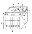
- a valve unit 10 consists of eight over its flat sides lined up plate valves 11 with essentially rectangular plate outline.
- To the two outer plate valves 11 of this valve unit 10 is another one appropriately contoured end plate 12 lined up.
- Plate valves are known for example from DE 44 13 657 and therefore do not need to be described in more detail.
- each plate valve includes a main valve and two pilot valves serving to control it can be actuated by electric drives, for example through electromagnetic arrangements.
- plate valves 11 and end plates 12 will covered by a likewise plate-like housing part 13, where one of the perpendicular to the planes of the flat sides of the Plate valves 11 extending flat side of the housing part 13 on the narrow sides of the plate valves according to the figure 11 is present. Additional retaining screws, not shown, Clamping arrangements or locking arrangements can be used for better fixation serve the housing part 13.
- the housing part 13 contains - in the perspective external view not recognizable - a microcomputer that does the usual Components of such has: processor, memory, Program memory, interfaces and the like.
- a display 14 On the top of the housing part 13 are a display 14, for example an LCD display, and a keyboard 15 arranged, connected to the microcomputer and for programming it and operation are trained.
- the keyboard is a relatively simple keyboard with multiple functions trained, but can in principle also a more extensive Keyboard provided with a larger number of keys his.
- Programming is, for example, menu-driven on the display 14 so that the number of buttons relative can be kept small.
- Alternatively or additionally can also provide touch buttons in a manner known per se be a fixed or variable part of the display claim. With a simple version, this can Display 14 and / or the keyboard 15 are also omitted. The programming is then done remotely, like this later is explained in more detail.
- Control outputs of the microcomputer are in perspective in one Representation of contact arrangement, also not recognizable, which are designed, for example, as a plug contact arrangement can be connected to the individual plate valves 11, to be able to control them.
- contact arrangement also not recognizable, which are designed, for example, as a plug contact arrangement can be connected to the individual plate valves 11, to be able to control them.
- the electrical Connections between plate valves 11 and microcomputer via the contact arrangement is established automatically.
- For controlling usually serve driver stages, which are also in the housing part 13 are arranged.
- sensors for example temperature or Pressure sensors or test sensors for the switching status, are also about the contact arrangement with the microcomputer connected to ensure the checking and monitoring of the valves and depending on possible tax data of the sensor signals.
- Socket for the electrical power supply to the plate valves 11 and one of the electronic components in the housing part 13 is used Socket, not shown, on the housing part 13.
- a DC voltage of 24 V can be fed in, the supply of the plate valves 11 also via this socket or another contact arrangement can.
- connection arrangement 16 on the housing part 13 is used for connection from external sensors and / or control signal transmitters to the microcomputer.
- the connection arrangement 16 is in the form of a plug connection connection arrangement shown, but it can if required also as a screw-plug connection arrangement or as Be clamp connection arrangement.
- the valve assembly can, for example, be close to one controlled by it Actuator arrangement, for example an arrangement of linear drives be arranged, the sensors on the connection arrangement 16 connected to the microcomputer in the housing part 13 are. This allows the entire system through the valve assembly work programmatically. Also signals from control signal generators, the switching signals depending on parameters, Status data or manual intervention supplied to the microcomputer via this connection arrangement 16 become.
- the control and / or programming of the microcomputer can via bus lines, not shown, or via a data network respectively.
- the bus lines are connected via a connection socket 17.
- the microcomputer itself can perform the functions of a Take over the bus station, or it is a separate bus station arranged between the connection socket 17 and the microcomputer.
- the microcomputer can alternatively via a Infrared interface 18 controlled and / or programmed become. Instead of an infrared interface, a Radio interface for wireless reception of control and programming data be provided.
- connection socket 17 and / or the infrared interface 18 or a radio interface can also be used to connect to be formed in a data network.
- the microcomputer points to this a web server, and a network interface and / or a modem on or is with such devices in the housing part 13 connected.
- the network interface can, for example, as Ethernet interface.
- connection socket 17 and / or the infrared point 18 or a radio interface can send data in both directions transmitted to and from the microcomputer, for example Programming data, sensor signal data, diagnostic data, monitoring data and / or service data. That way is one Remote diagnosis and monitoring of the valve station and, if applicable associated actuator arrangements wirelessly or over a network, for example the Internet.
- Valve units also controlled directly via control lines are connected to the corresponding connection sockets 19 can be.
- the data transfer between the described valve assembly and other valve units can be done in parallel or via an internal serial bus.
- the housing part 13 can be removed and in more favorable environment, for example at work or Desk, can be programmed or set, provided manual programming using a keyboard 15 is provided is. Then it can be attached to the valve unit again 10 are plugged in and, if necessary, additionally fixed. In the event of malfunctions, this can be done in a simple manner entire housing part 13 with all electronic components be replaced.
- the individual plate valves 11 can also be operated directly “manually", either via the microcomputer takes place or directly actuates a corresponding one Shift key for direct actuation.
- the individual plate valves 11 can also be actuated be provided with manual switches or buttons.
Description
Claims (11)
- Ventilanordnung mit einer aus mehreren aneinandergereihten, elektrisch betätigbaren Ventilen bestehenden Ventileinheit, an der ein Gehäuseteil angeordnet ist, das eine programmierbare als Mikrorechner ausgebildete elektronische Steuereinrichtung für die Ventile besitzt und mit diesen wenigstens über Steuerleitungen verbunden ist, mit wenigstens einer Netz- und/oder Busanschlussanordnung (17) zum Anschluss der Steuereinrichtung an ein externes Netz oder eine externe Busanordnung am Gehäuseteil (13), über das oder die die Steuereinrichtung programmierbar ist, und mit einer Anschlussanordnung (16) zum Anschließen von externen Sensoren und/oder Steuersignalgebern an die Steuereinrichtung, dadurch gekennzeichnet, dass die Steuereinrichtung mit einem Webserver versehen ist.
- Ventilanordnung nach Anspruch 1, dadurch gekennzeichnet, dass die Anschlussanordnung (16) mehrere als Schraubsteckanschlüsse und/oder Klemmanschlüsse und/oder Steckverbindungsanschlüsse ausgebildete Anschlüsse besitzt.
- Ventilanordnung nach Anspruch 1 oder 2, dadurch gekennzeichnet, dass das Gehäuseteil (13) ein zur Programmierung geeignetes Display (14) und/oder eine als Einstell- und Programmiereinrichtung ausgebildete Tastatur (15) besitzt.
- Ventilanordnung nach einem der vorhergehenden Ansprüche, dadurch gekennzeichnet, daß das Gehäuseteil (13) mit einer Infrarot- oder Funkschnittstelle (18) zur Datenübertragung versehen ist, insbesondere Programmierdaten und/oder Sensorsignaldaten und/oder Diagnosedaten und/oder Überwachungsdaten und/oder Servicedaten.
- Ventilanordnung nach einem der vorhergehenden Ansprüche, dadurch gekennzeichnet, daß das Gehäuseteil (13) lösbar an die Ventileinheit (10) ansteckbar ist, wobei eine Kontaktanordnung vorgesehen ist, die beim Anstecken die elektrischen Verbindungen zu den Ventilen (11) automatisch herstellt.
- Ventilanordnung nach Anspruch 5, dadurch gekennzeichnet, daß das Gehäuseteil (13) auch im von der Ventileinheit (10) abgenommenen Zustand programmierbar ist.
- Ventilanordnung nach einem der vorhergehenden Ansprüche, dadurch gekennzeichnet, daß das Gehäuseteil (13) plattenartig ausgebildet ist.
- Ventilanordnung nach einem der vorhergehenden Ansprüche, dadurch gekennzeichnet, daß die Ventile als plattenartige Ventile ausgebildet sind, die mit ihren Flachseiten aneinanderliegen, und daß das Gehäuseteil (13) die aneinanderliegenden Ventile quer zur Ebene der Flachseiten übergreift.
- Ventilanordnung nach einem der vorhergehenden Ansprüche, dadurch gekennzeichnet, daß die elektronische Steuereinrichtung mit an oder in den Ventilen (11) angeordneten Sensoren verbunden ist.
- Ventilanordnung nach einem der vorhergehenden Ansprüche, dadurch gekennzeichnet, dass die Steuereinrichtung mit einer Netzschnittstelle und/oder einem Modem zum Datenaustausch mit einem Netzwerk über die Netz- und/oder Busanschlussanordnung (17) und/oder die Infrarot- oder Funkschnittstelle (18) versehen ist.
- Ventilanordnung nach Anspruch 10, dadurch gekennzeichnet, dass die Netzschnittstelle als Ethernet-Schnittstelle ausgebildet ist.
Applications Claiming Priority (3)
| Application Number | Priority Date | Filing Date | Title |
|---|---|---|---|
| DE20006295U DE20006295U1 (de) | 2000-04-06 | 2000-04-06 | Ventilanordnung |
| DE20006295U | 2000-04-06 | ||
| PCT/EP2001/003740 WO2001077534A1 (de) | 2000-04-06 | 2001-04-03 | Ventilanordnung |
Publications (2)
| Publication Number | Publication Date |
|---|---|
| EP1272767A1 EP1272767A1 (de) | 2003-01-08 |
| EP1272767B1 true EP1272767B1 (de) | 2003-11-26 |
Family
ID=7939849
Family Applications (1)
| Application Number | Title | Priority Date | Filing Date |
|---|---|---|---|
| EP01927853A Expired - Lifetime EP1272767B1 (de) | 2000-04-06 | 2001-04-03 | Ventilanordnung |
Country Status (4)
| Country | Link |
|---|---|
| EP (1) | EP1272767B1 (de) |
| AT (1) | ATE255205T1 (de) |
| DE (2) | DE20006295U1 (de) |
| WO (1) | WO2001077534A1 (de) |
Cited By (3)
| Publication number | Priority date | Publication date | Assignee | Title |
|---|---|---|---|---|
| DE102006018220A1 (de) * | 2006-04-19 | 2007-10-25 | Festo Ag & Co | Ventilbatterie und Kommunikationsverfahren dafür |
| US8156965B2 (en) | 2007-08-16 | 2012-04-17 | Festo Ag & Co. Kg | Modular arrangement with modules, which are added in a series direction and are formed at least partially as valve modules |
| DE102016110904A1 (de) | 2016-06-14 | 2017-12-14 | Bürkert Werke GmbH | Ventilbaugruppe |
Families Citing this family (11)
| Publication number | Priority date | Publication date | Assignee | Title |
|---|---|---|---|---|
| DE10048049A1 (de) * | 2000-09-28 | 2002-05-02 | Festo Ag & Co | Fluidtechnische Einrichtung mit einer Diagnoseeinrichtung |
| EP1316732B1 (de) | 2001-11-29 | 2004-09-08 | Festo AG & Co | Fluidbetätigte Arbeitsvorrichtung |
| DE20203943U1 (de) | 2002-03-12 | 2003-07-31 | Hawe Hydraulik Gmbh & Co Kg | Hydraulikbaugruppe und Steckerleiste |
| EP1398677B1 (de) * | 2002-09-03 | 2009-12-23 | futronic GmbH | Modulares Steuerungssystem für eine Glasformmaschine |
| AU2003253219A1 (en) | 2002-10-07 | 2004-04-23 | Bucher Hydraulics Gmbh | Regulating device for a hydraulic system |
| DE50303812D1 (de) | 2003-04-01 | 2006-07-27 | Festo Ag & Co | Steuergerät, Steuermodul, Modulbatterie und Steuerungssystem |
| DE102004017894B3 (de) * | 2004-04-13 | 2005-11-24 | Festo Ag & Co. | Steuermodulanordnung und Druckluft-Wartungseinheit |
| US7753740B2 (en) | 2007-07-20 | 2010-07-13 | Numatics, Incorporated | Modular electrical bus system |
| KR102402810B1 (ko) * | 2015-11-03 | 2022-05-27 | 페스토 에스이 운트 코. 카게 | 공압 밸브 조립체의 애플리케이션 기반 제어 |
| WO2017182511A2 (de) * | 2016-04-21 | 2017-10-26 | Festo Ag & Co. Kg | Applikationsbasierte steuerung einer ventilscheibe |
| CN108946846A (zh) * | 2018-10-09 | 2018-12-07 | 圣都家居装饰有限公司 | 一种家居智能给水系统及给水方法 |
Family Cites Families (7)
| Publication number | Priority date | Publication date | Assignee | Title |
|---|---|---|---|---|
| EP0603395B1 (de) * | 1991-09-10 | 1999-05-06 | Smc Kabushiki Kaisha | Flüssigkeitsdruck betätigte vorrichtung |
| WO1993005326A1 (en) * | 1991-09-10 | 1993-03-18 | Smc Kabushiki Kaisha | Fluid pressure machine |
| DE4413657C1 (de) | 1994-04-20 | 1995-11-02 | Festo Kg | Ventilanordnung |
| DE19526459A1 (de) * | 1995-07-20 | 1997-01-23 | Festo Kg | Ventilanordnung |
| DE19840597A1 (de) | 1998-09-05 | 2000-03-16 | Festo Ag & Co | Ventilanordnung mit mindestens einer aus mehreren elektrisch betätigbaren Ventilen bestehenden Ventileinheit |
| DE19840596C1 (de) | 1998-09-05 | 1999-08-05 | Festo Ag & Co | Ventilanordnung mit mindestens einer aus mehreren elektrisch betätigbaren Ventilen bestehenden Ventileinheit |
| DE29905865U1 (de) * | 1999-03-31 | 1999-06-17 | Festo Ag & Co | Ventileinheit |
-
2000
- 2000-04-06 DE DE20006295U patent/DE20006295U1/de not_active Expired - Lifetime
-
2001
- 2001-04-03 EP EP01927853A patent/EP1272767B1/de not_active Expired - Lifetime
- 2001-04-03 WO PCT/EP2001/003740 patent/WO2001077534A1/de active IP Right Grant
- 2001-04-03 DE DE50101038T patent/DE50101038D1/de not_active Expired - Lifetime
- 2001-04-03 AT AT01927853T patent/ATE255205T1/de not_active IP Right Cessation
Cited By (4)
| Publication number | Priority date | Publication date | Assignee | Title |
|---|---|---|---|---|
| DE102006018220A1 (de) * | 2006-04-19 | 2007-10-25 | Festo Ag & Co | Ventilbatterie und Kommunikationsverfahren dafür |
| DE102006018220B4 (de) * | 2006-04-19 | 2008-07-31 | Festo Ag & Co | Ventilbatterie und Kommunikationsverfahren dafür |
| US8156965B2 (en) | 2007-08-16 | 2012-04-17 | Festo Ag & Co. Kg | Modular arrangement with modules, which are added in a series direction and are formed at least partially as valve modules |
| DE102016110904A1 (de) | 2016-06-14 | 2017-12-14 | Bürkert Werke GmbH | Ventilbaugruppe |
Also Published As
| Publication number | Publication date |
|---|---|
| ATE255205T1 (de) | 2003-12-15 |
| DE50101038D1 (de) | 2004-01-08 |
| WO2001077534A1 (de) | 2001-10-18 |
| EP1272767A1 (de) | 2003-01-08 |
| DE20006295U1 (de) | 2000-07-20 |
Similar Documents
| Publication | Publication Date | Title |
|---|---|---|
| EP1272767B1 (de) | Ventilanordnung | |
| EP0608245B1 (de) | Elektro-pneumatische steuereinrichtung | |
| EP1174781B1 (de) | Einrichtung zur Signalübertragung | |
| EP2072192A1 (de) | Steuermodul | |
| EP0909898B1 (de) | Druckluftwartungseinheit | |
| EP0803653B1 (de) | Pneumatische Betätigungsanordnung | |
| EP1711717B1 (de) | Druckluftwartungsvorrichtung | |
| EP2441215A1 (de) | Vorrichtung zur übertragung von daten zwischen einem seriellen datenbus und arbeitsmodulen, wie aktormodulen und/oder e/a-modulen | |
| EP2258153B1 (de) | Elektrisches baukastenmodulsystem mit einem variabel einsetzbaren feldbusmodul | |
| DE102018129835A1 (de) | Steuerungssystem, Kopplermodul und Verfahren zur Montage eines Steuerungssystems | |
| DE10155481A1 (de) | Einrichtung zur Steuerung und Überwachung der Freigabe von Empfangssignalen an Anschlussstellen innerhalb von kabelgebundenen Hausverteilungsanlagen | |
| DE102019127195A1 (de) | Modulares Interfacesystem zum Anschließen einer Steuerungseinrichtung und von Feldgeräte | |
| EP0984169B1 (de) | Ventilanordnung mit mindestens einer aus mehreren elektrisch betätigbaren Ventilen bestehenden Ventileinheit | |
| DE102010035409A1 (de) | Wendeplatten-Spritzgießmaschine mit dezentralem Steuerungs- und Regelgerät | |
| EP0629783A1 (de) | Kombinierte Steuerung von Pneumatik- und Hydraulikventilen | |
| EP2014409A1 (de) | Mehrachsen-Drehkopf mit integrierter Steuereinrichtung und Koordinatenmessmaschine mit solch einem Mehrachsen-Drehkopf | |
| EP1180602B1 (de) | Steuerventileinrichtung sowie als Bestandteil derselben geeignetes Ventil | |
| DE102009051610A1 (de) | Kupplung zum Einsetzen zwischen ein Rechnergehäuse und eine das Rechnergehäuse tragende Wand- oder Deckenhalterung, sowie Bedienstation | |
| DE102007026151A1 (de) | Bedienstation mit einem Rechnergehäuse, einem Tragarm und einer zwischen dem Rechnergehäuse und dem Tragarm angeordneten mechanischen Kupplung mit selbsttätiger elektrischer Kopplung | |
| EP0984168B1 (de) | Ventilanordnung mit mindestens einer aus mehreren elektrisch betätigbaren Ventilen bestehenden Ventileinheit | |
| DE112019001766T5 (de) | Handmechanismus und Greifroboter | |
| EP3611806B1 (de) | Adapter und vakuumsystem | |
| EP1664950B1 (de) | Einrichtung zur kommunikation mit einer anlage | |
| DE102018001341A1 (de) | Lösbare Kupplung zum Einsetzen zwischen eine Bedieneinheit und eine die Bedieneinheit tragende Decken- oder Wandhalterung einer Bedienstation zur Bedienung von Maschinen, Industrieanlagen oder dergleichen, sowie Bedienstation mit einer solchen Kupplung und Montageverfahren | |
| DE19828024B4 (de) | Regelanordnung zur Regelung von wenigstens einem an einem Bussystem angeschlossenen Positionierantrieb, insbesondere pneumatischen Positionierantrieb |
Legal Events
| Date | Code | Title | Description |
|---|---|---|---|
| PUAI | Public reference made under article 153(3) epc to a published international application that has entered the european phase |
Free format text: ORIGINAL CODE: 0009012 |
|
| 17P | Request for examination filed |
Effective date: 20021102 |
|
| AK | Designated contracting states |
Kind code of ref document: A1 Designated state(s): AT BE CH CY DE DK ES FI FR GB GR IE IT LI LU MC NL PT SE TR |
|
| GRAH | Despatch of communication of intention to grant a patent |
Free format text: ORIGINAL CODE: EPIDOS IGRA |
|
| GRAS | Grant fee paid |
Free format text: ORIGINAL CODE: EPIDOSNIGR3 |
|
| GRAA | (expected) grant |
Free format text: ORIGINAL CODE: 0009210 |
|
| AK | Designated contracting states |
Kind code of ref document: B1 Designated state(s): AT BE CH CY DE DK ES FI FR GB GR IE IT LI LU MC NL PT SE TR |
|
| PG25 | Lapsed in a contracting state [announced via postgrant information from national office to epo] |
Ref country code: IE Free format text: LAPSE BECAUSE OF FAILURE TO SUBMIT A TRANSLATION OF THE DESCRIPTION OR TO PAY THE FEE WITHIN THE PRESCRIBED TIME-LIMIT Effective date: 20031126 Ref country code: CY Free format text: LAPSE BECAUSE OF FAILURE TO SUBMIT A TRANSLATION OF THE DESCRIPTION OR TO PAY THE FEE WITHIN THE PRESCRIBED TIME-LIMIT Effective date: 20031126 Ref country code: NL Free format text: LAPSE BECAUSE OF FAILURE TO SUBMIT A TRANSLATION OF THE DESCRIPTION OR TO PAY THE FEE WITHIN THE PRESCRIBED TIME-LIMIT Effective date: 20031126 Ref country code: TR Free format text: LAPSE BECAUSE OF FAILURE TO SUBMIT A TRANSLATION OF THE DESCRIPTION OR TO PAY THE FEE WITHIN THE PRESCRIBED TIME-LIMIT Effective date: 20031126 |
|
| REG | Reference to a national code |
Ref country code: GB Ref legal event code: FG4D Free format text: NOT ENGLISH |
|
| REG | Reference to a national code |
Ref country code: CH Ref legal event code: EP |
|
| GBT | Gb: translation of ep patent filed (gb section 77(6)(a)/1977) | ||
| REF | Corresponds to: |
Ref document number: 50101038 Country of ref document: DE Date of ref document: 20040108 Kind code of ref document: P |
|
| REG | Reference to a national code |
Ref country code: IE Ref legal event code: FG4D Free format text: GERMAN |
|
| PG25 | Lapsed in a contracting state [announced via postgrant information from national office to epo] |
Ref country code: DK Free format text: LAPSE BECAUSE OF FAILURE TO SUBMIT A TRANSLATION OF THE DESCRIPTION OR TO PAY THE FEE WITHIN THE PRESCRIBED TIME-LIMIT Effective date: 20040226 Ref country code: SE Free format text: LAPSE BECAUSE OF FAILURE TO SUBMIT A TRANSLATION OF THE DESCRIPTION OR TO PAY THE FEE WITHIN THE PRESCRIBED TIME-LIMIT Effective date: 20040226 Ref country code: GR Free format text: LAPSE BECAUSE OF FAILURE TO SUBMIT A TRANSLATION OF THE DESCRIPTION OR TO PAY THE FEE WITHIN THE PRESCRIBED TIME-LIMIT Effective date: 20040226 |
|
| PG25 | Lapsed in a contracting state [announced via postgrant information from national office to epo] |
Ref country code: ES Free format text: LAPSE BECAUSE OF FAILURE TO SUBMIT A TRANSLATION OF THE DESCRIPTION OR TO PAY THE FEE WITHIN THE PRESCRIBED TIME-LIMIT Effective date: 20040309 |
|
| PG25 | Lapsed in a contracting state [announced via postgrant information from national office to epo] |
Ref country code: AT Free format text: LAPSE BECAUSE OF NON-PAYMENT OF DUE FEES Effective date: 20040403 Ref country code: LU Free format text: LAPSE BECAUSE OF NON-PAYMENT OF DUE FEES Effective date: 20040403 |
|
| PG25 | Lapsed in a contracting state [announced via postgrant information from national office to epo] |
Ref country code: BE Free format text: LAPSE BECAUSE OF NON-PAYMENT OF DUE FEES Effective date: 20040430 Ref country code: MC Free format text: LAPSE BECAUSE OF NON-PAYMENT OF DUE FEES Effective date: 20040430 |
|
| NLV1 | Nl: lapsed or annulled due to failure to fulfill the requirements of art. 29p and 29m of the patents act | ||
| REG | Reference to a national code |
Ref country code: IE Ref legal event code: FD4D |
|
| ET | Fr: translation filed | ||
| PLBE | No opposition filed within time limit |
Free format text: ORIGINAL CODE: 0009261 |
|
| STAA | Information on the status of an ep patent application or granted ep patent |
Free format text: STATUS: NO OPPOSITION FILED WITHIN TIME LIMIT |
|
| BERE | Be: lapsed |
Owner name: *FESTO A.G. & CO. Effective date: 20040430 |
|
| 26N | No opposition filed |
Effective date: 20040827 |
|
| PG25 | Lapsed in a contracting state [announced via postgrant information from national office to epo] |
Ref country code: LI Free format text: LAPSE BECAUSE OF NON-PAYMENT OF DUE FEES Effective date: 20050430 Ref country code: CH Free format text: LAPSE BECAUSE OF NON-PAYMENT OF DUE FEES Effective date: 20050430 |
|
| REG | Reference to a national code |
Ref country code: CH Ref legal event code: PL |
|
| PG25 | Lapsed in a contracting state [announced via postgrant information from national office to epo] |
Ref country code: PT Free format text: LAPSE BECAUSE OF NON-PAYMENT OF DUE FEES Effective date: 20040426 |
|
| PGFP | Annual fee paid to national office [announced via postgrant information from national office to epo] |
Ref country code: FI Payment date: 20080319 Year of fee payment: 8 |
|
| PG25 | Lapsed in a contracting state [announced via postgrant information from national office to epo] |
Ref country code: FI Free format text: LAPSE BECAUSE OF NON-PAYMENT OF DUE FEES Effective date: 20090403 |
|
| REG | Reference to a national code |
Ref country code: FR Ref legal event code: PLFP Year of fee payment: 16 |
|
| REG | Reference to a national code |
Ref country code: FR Ref legal event code: PLFP Year of fee payment: 17 |
|
| PGFP | Annual fee paid to national office [announced via postgrant information from national office to epo] |
Ref country code: FR Payment date: 20170424 Year of fee payment: 17 |
|
| PGFP | Annual fee paid to national office [announced via postgrant information from national office to epo] |
Ref country code: IT Payment date: 20170420 Year of fee payment: 17 |
|
| PGFP | Annual fee paid to national office [announced via postgrant information from national office to epo] |
Ref country code: GB Payment date: 20180227 Year of fee payment: 18 |
|
| PG25 | Lapsed in a contracting state [announced via postgrant information from national office to epo] |
Ref country code: FR Free format text: LAPSE BECAUSE OF NON-PAYMENT OF DUE FEES Effective date: 20180430 Ref country code: IT Free format text: LAPSE BECAUSE OF NON-PAYMENT OF DUE FEES Effective date: 20180403 |
|
| GBPC | Gb: european patent ceased through non-payment of renewal fee |
Effective date: 20190403 |
|
| PG25 | Lapsed in a contracting state [announced via postgrant information from national office to epo] |
Ref country code: GB Free format text: LAPSE BECAUSE OF NON-PAYMENT OF DUE FEES Effective date: 20190403 |
|
| REG | Reference to a national code |
Ref country code: DE Ref legal event code: R082 Ref document number: 50101038 Country of ref document: DE Representative=s name: PATENTANWAELTE MAGENBAUER & KOLLEGEN PARTNERSC, DE Ref country code: DE Ref legal event code: R081 Ref document number: 50101038 Country of ref document: DE Owner name: FESTO SE & CO. KG, DE Free format text: FORMER OWNER: FESTO AG & CO. KG, 73734 ESSLINGEN, DE Ref country code: DE Ref legal event code: R081 Ref document number: 50101038 Country of ref document: DE Owner name: FESTO AG & CO. KG, DE Free format text: FORMER OWNER: FESTO AG & CO. KG, 73734 ESSLINGEN, DE |
|
| PGFP | Annual fee paid to national office [announced via postgrant information from national office to epo] |
Ref country code: DE Payment date: 20200226 Year of fee payment: 20 |
|
| REG | Reference to a national code |
Ref country code: DE Ref legal event code: R071 Ref document number: 50101038 Country of ref document: DE |