EP0903541B1 - Glühkerze - Google Patents
Glühkerze Download PDFInfo
- Publication number
- EP0903541B1 EP0903541B1 EP19980117773 EP98117773A EP0903541B1 EP 0903541 B1 EP0903541 B1 EP 0903541B1 EP 19980117773 EP19980117773 EP 19980117773 EP 98117773 A EP98117773 A EP 98117773A EP 0903541 B1 EP0903541 B1 EP 0903541B1
- Authority
- EP
- European Patent Office
- Prior art keywords
- heater
- glow plug
- heater casing
- casing
- hollow housing
- Prior art date
- Legal status (The legal status is an assumption and is not a legal conclusion. Google has not performed a legal analysis and makes no representation as to the accuracy of the status listed.)
- Expired - Lifetime
Links
Images


Classifications
-
- F—MECHANICAL ENGINEERING; LIGHTING; HEATING; WEAPONS; BLASTING
- F23—COMBUSTION APPARATUS; COMBUSTION PROCESSES
- F23Q—IGNITION; EXTINGUISHING-DEVICES
- F23Q7/00—Incandescent ignition; Igniters using electrically-produced heat, e.g. lighters for cigarettes; Electrically-heated glowing plugs
- F23Q7/001—Glowing plugs for internal-combustion engines
Definitions
- the present invention relates generally to a glow plug designed to preheat a combustion chamber of a diesel engine for ensuring quick starting, and more particularly to an improved structure of a glow plug designed to provide for a desired hermetic seal between a heater and a housing in easy assembling.
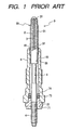
- Fig. 1 shows a conventional sheathed glow plug used as a preheating element for diesel engines.
- the glow plug 9 includes generally a heater 90, a central rod 4, and a housing 5.
- the heater 90 includes a metallic tube 91 which is filled with an insulating powder 2 and which has disposed therein a heating coil 3.
- the central rod 4 is disposed within the housing 5 and partially inserted into the insulating powder 2.
- the heating coil 3 is joined at an end 31 to an inner wall of a closed head of the tube 91 and at an end 32 to a head of the central rod 4.
- the heater 90 is retained by the housing 5 in tight engagement of a press fit wall 95 of the tube 91 with an inner wall 55 of the housing 5.
- the central rod 4 is installed within the housing 5 through a nut 71, resinous bush 72, an insulating O-ring 73, and a resinous washer 74.
- the production of the glow plug 9 involves insertion of the heating coil 3 and the central rod 4 into the metallic tube 91, packing the insulating powder 2 into the metallic tube 91, swaging the metallic tube 91 to hold the central rod 4 tightly, and press-fitting the heater 90 into the housing 5.
- the press-fitting of the heater 90 into the housing 5 must be so achieved as to ensure airtight engagement therebetween enough to withstand a high pressure of about 150 atmospheres acting on the glow plug 9 during use.
- This requires high roundness and fine surface roughness (i.e., a mirror-finished surface) of the press fit wall 95 of the heater 90, which generally requires use of an expensive and high-performance swaging machine.
- Japanese Patent Second Publication No. 59-52726 teaches the airtight engagement of a heater with a housing achieved by inserting the heater with a groove into the housing and staking a portion of a peripheral wall of the housing in the groove of the heater. This, however, has the disadvantages of requiring an additional process of the staking.
- a glow plug which comprises: (a) a hollow housing having a given length; (b) a heater assembly including a heater casing, a heating element, and a power supply rod, the heater casing having disposed therein the heating element connecting with the power supply rod and also having formed on a periphery thereof a press fit wall press-fitted into the hollow housing in tight engagement with an inner peripheral wall of the hollow housing; and (c) an uneven surface formed on one of the press fit wall of the heater casing and the inner peripheral wall of the hollow housing, the uneven surface having formed thereon a pattern which has a length oriented at an angle relative to a longitudinal center line of the glow plug.
- the uneven surface has a surface roughness of 25 ⁇ m or less (Rz).
- the uneven surface occupies 20% or more of an area of one of the press fit wall of the heater casing and the inner peripheral wall of the hollow housing.
- the uneven surface is patterned with lines which are oriented at 30° or more relative to the longitudinal center line of the glow plug.
- the lines of the uneven surface are formed with one of fine grooves and protrusions.
- the press fit wall of the heater casing has a hardness different from that of the inner peripheral wall of the hollow housing.
- An insulating powder is disposed within the heater casing to insulate the heating element from the heater casing.
- the heating casing has a given length and has formed therein an open end.
- the power supply rod is partially inserted into the insulating powder through the open end of the heating casing.
- a sealing member is disposed within the heater casing.
- the sealing member is made of a sealing liquid which is penetrated into a portion of the insulating powder exposed to the open end of the heater casing and which is hardened to form an airtight seal in the open end of the heater casing.
- the thickness of the sealing member is smaller than the length of a portion of the power supply rod embedded into the insulating powder.
- the sealing member has a permeability of 10 -5 cc/sec ⁇ kg/cm 2 or less and made of a silicone rubber.
- the thickness of the sealing member is 0.5 mm or more.
- a glow plug production method which comprises the steps of: (a) preparing a hollow housing having a given length; (b) preparing a heater assembly including a heater casing and a heating element disposed within the heater casing, the heater casing having a press fit wall formed on a periphery thereof; (c) machining one of the press fit wall of the heater casing and the inner peripheral wall of the hollow housing so as to form an uneven surface with a pattern which has a length oriented at an angle relative to a longitudinal center line of the hollow housing; and (d) forcing the heater casing of the heater assembly into the hollow housing to establish tight engagement between the press fit wall of the heater casing and the inner peripheral wall of the hollow housing.
- the machining step patterns the uneven surface with lines formed with one of fine grooves or protrusions.
- a machining step is further provided which, before forcing the heater casing into the hollow housing, machines an end portion of the heater casing which is to be inserted into the hollow housing to form a guide stem having a diameter smaller than that of the inner peripheral wall of the hollow housing and a tapered wall connecting the press fit wall and the guide stem.
- the guide stem has a length of 3 mm or more.
- a forming step may further be provided which forms a tapered inner wall in the hollow cylinder oriented at an angle relative to the longitudinal center line of the hollow cylinder which is greater than an angle at which the tapered wall of the heater casing is oriented relative to a longitudinal center line of the heater casing.
- the forcing step includes a grasping step of grasping a periphery of the heater casing using a collet and a pressing step of pressing the collect to force the heater casing of the heater assembly into the hollow housing.
- the forcing step further includes a mounting step of, before the pressing step, mounting the heater casing in the hollow housing in alignment.
- the forcing step further includes a second pressing step of pressing a head of the heater casing using a press member after a load applied to the heater casing from the collet reaches a given level.
- the forcing step may alternatively include a grasping step of grasping axially spaced peripheral portions of the heater casing using a first and a second collet and a pressing step of pressing the first and second collets under different pressures, respectively, to force the heater casing of the heater assembly into the hollow housing.
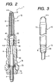
- a glow plug 1 according to the first embodiment of the present invention.
- the glow plug 1 includes generally a housing 5 having formed therein a cylindrical bore 50, a heater 10 press-fitted into the bore 50, and a central rod 4 connecting at an end with a power supply (not shown).
- the attachment of the heater 10 to the housing 5 is achieved by bringing a press fit wall 15 formed on an end portion of the heater 10 into tight engagement with a small-diameter inner wall 55 of the cylindrical bore 50.
- the press fit wall 15 has an uneven surface 60 on which fine grooves or scratches 6 are formed. Each of the scratches 6 has a length oriented at an angle of 30° or more relative to the longitudinal center line of the glow plug 1 (i.e., the heater 10). It is advisable that the surface roughness (Rz) of the uneven surface 60 be 25 ⁇ m or more for ensuring airtight sealing between the heater 10 and the housing 5.
- the heater 10 includes a metallic tube 11 having a closed head 111 and a heating coil 3 disposed within the tube 11.
- the tube 11 is filled with an insulating powder 2.
- the central rod 4 has a head 41 inserted through an open end 112 of the tube 11 into the insulating powder 2.
- the heating coil 3 is welded at an end 31 to an inner wall of the head 111 of the tube 11 and at an end 32 to the tip of the central rod 4.
- Other arrangements are identical with those shown in Fig. 1, and explanation thereof in detail will be omitted here.
- the metallic tube 11 and the central rod 4 to which the end 32 of the heating coil 3 is attached are first prepared.
- the heating coil 3 is inserted into the metallic tube 11 and welded at the end 31 to the inner wall of the head 111 of the metallic tube 11.
- the insulating powder 2 made of magnesia (MgO) is packed into the metallic tube 11 to insulate the heating coil 3 and the head 41 of the central rod 4 from the inner wall of the metallic tube 11.
- the metallic tube 11 is swaged to decrease the diameter thereof, thereby increasing the density of the insulating powder 2 in the metallic tube 11 to join the central rod 4 and the heater 10 together.
- the base portion of the metallic tube 11 is ground to form the press fit wall 15 which has a preselected roundness and which has formed thereon the uneven surface 60 patterned with lines (i.e., the scratches 6) as shown in Fig. 3.
- the adjustment of the roundness and formation of the line pattern are achieved by controlling the feed of a grinding wheel.
- the uneven surface 60 occupies 20% or more, preferably 90% or more (100% in this embodiment) of a peripheral area of the press fit wall 15 and has formed thereon the scratches 6 uniformly.
- the scratches 6 may be formed with feed lines extending substantially perpendicular to the longitudinal center line of the metallic tube 11.
- the heater 10 is, as shown in Fig. 4, forced into the housing 5.
- the housing 5 has, as described above, formed therein the cylindrical bore 50 which extends longitudinally and which has a heater insertion opening 51. In the cylindrical bore 50, the small-diameter inner wall 55 is formed.
- the housing 5 is made from material having the hardness smaller than that of the heater 10.
- the housing 5 is, as clearly shown in Fig. 4, placed on a holder 86 with the heater insertion opening 51 facing upward.
- the heater 10 retained at the head by a press block 81 is inserted into the housing 5 and then pressed by the press block 81 downward to bring the press fit wall 15 into tight engagement with the small-diameter inner wall 55 of the housing 5.
- the press fit wall 15 of the heater 10 be applied with lubricating oil such as fluoro grease, silicone grease, synthetic hydrocarbon-based grease, polyglycol-based grease, or phenylether-based grease in advance for reducing the friction between the press fit wall 15 and the small-diameter inner wall 55 during insertion of the heater 10 into the housing 5.
- lubricating oil such as fluoro grease, silicone grease, synthetic hydrocarbon-based grease, polyglycol-based grease, or phenylether-based grease
- a nut 71, a resinous bush 72, an O-ring 73 made from insulating material, and a resinous washer 74 are installed in and on the end of the housing 5 to hold the central rod 4 hermetically within the housing 5.
- Fig. 5 shows the first modification of the heater 10 which has an uneven surface 62 formed on the press fit wall 15 of the metallic tube 11.
- the whole of the uneven surface 62 is patterned with a spiral line 6 using a cutting tool.
- Other arrangements are identical with those in the first embodiment.
- Fig. 6 shows the second modification of the heater 10 which has an uneven surface 63 formed on the press fit wall 15 of the metallic tube 11.
- the whole of the uneven surface 63 is patterned with latticed lines 6 in knurling, for example.
- Other arrangements are identical with those in the first embodiment.
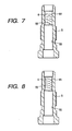
- Fig. 7 shows the second embodiment of the invention which has formed on the small-diameter inner wall 55 of the housing 5 an uneven surface 64 instead of the uneven surface 60 on the press fit wall 15 of the heater 10 in the first embodiment.
- the uneven surface 64 has formed thereon the scratches 6 in the same pattern as that of the first embodiment.
- the housing 5 is made from material having the hardness greater than that of the heater 10. Other arrangements are identical with those in the first embodiment.
- Fig. 8 shows the first modification of the second embodiment which has an uneven surface 65 formed on the small-diameter inner wall 55 of the housing 5.
- the uneven surface 65 is patterned with a spiral line 6 using a cutting tool.
- Other arrangements are identical with those of the second embodiment.
- Fig. 9 shows the second modification of the second embodiment which has an uneven surface 66 formed on the small-diameter inner wall 55 of the housing 5.
- the uneven surface 66 is patterned with latticed lines 6 in knurling, for example. Other arrangements are identical with those of the second embodiment.
- the above described patterns on the press fit wall 15 of the metallic tube 11 and the small-diameter inner wall 55 of the housing 5 are defined by fine grooves, they may alternatively be formed with fine protrusions or ridges.
- the press-fitting of the heater 10 into the housing 5 causes the ridges to be forced into the small-diameter inner wall 55 or the press fit wall 15, whichever is the softer, to form barriers which establish airtight engagement between the heater 10 and the housing 5.
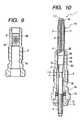
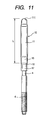
- Fig. 10 shows the third embodiment of the glow plug 1 which has a heater 10 different in structure from the ones in the above embodiments.
- the heater 10 has a metallic tube 11.
- the metallic tube 11 includes a guide stem 17 which is smaller in diameter than the press fit wall 15 and extends from the press fit wall 15 through a tapered wall 16.
- Other arrangements are identical with those of the first embodiment, and explanation thereof in detail will be omitted here.
- the metallic tube 11 and the central rod 4 to which the end 32 of the heating coil 3 is attached are first prepared.
- the heating coil 3 is inserted into the metallic tube 11 and welded at the end 31 to the inner wall of the head 111 of the metallic tube 11.
- the insulating powder 2 made of magnesia (MgO) is packed into the metallic tube 11 to insulate the heating coil 3 and the head 41 of the central rod 4 from the inner wall of the metallic tube 11.
- the metallic tube 11 is swaged to decrease the diameter thereof, thereby increasing the density of the insulating powder 2 in the metallic tube 11 to hold the central rod 4 in the heater 10 tightly.
- a base portion of the metallic tube 11, as indicated by a broken line in Fig. 11, is ground or machined with a cutting tool to form the press fit wall 15, the tapered wall 16, and the guide stem 17.
- the swaging usually causes the overall length of the metallic tube 11 to change, but the length L from the head 111 of the metallic tube 11 to a lower end of the press fit wall 15, as viewed in the drawing, is fixed, while the length of the guide stem 17 is changed in accordance with the change in overall length of the metallic tube 11. It is advisable that the location of the pass wall 15 from the head 111 of the metallic tube 11 be determined under the condition that the guide stem 17 has a length of 3 mm or more for ensuring alignment of the heater 10 with the housing 5 when they are joined temporarily.
- the uneven surface 60 is formed in the same manner as that in either of the first and second embodiments.
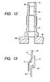
- the housing 5 is, as shown in Fig. 12, prepared.
- the heater 10 is forced into the housing 5 in a manner as discussed below.
- the housing 5 has, as described above, the tapered surface 56 formed by chamfering an edge of the small-diameter inner wall 55 facing the heater insertion opening 51.
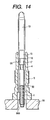
- An inclination ⁇ of the tapered surface 56 relative to the longitudinal center line of the housing 6 is, as clearly shown in Fig. 13, greater than an inclination ⁇ of the tapered wall 16 of the heater 10 ( ⁇ ⁇ ⁇ ⁇ 45°).
- the housing 5 is, as shown in Fig. 12, placed on the holder 86 with the heater insertion opening 51 facing upward.
- the holder 86 unlike a conventional structure wherein the housing 5 is retained horizontally, has formed therein a through hole 860 coaxially with the cylindrical bore 50 of the housing 5.
- the through hole 860 has the diameter greater than the outer diameter of the central rod 4, but smaller than the outer diameter of the housing 5.
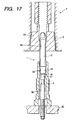
- the central rod 4 of the heater 10 is, as shown in Fig. 14, inserted into the cylindrical bore 50 of the housing 5 to join the heater 10 and the housing 5 temporarily.
- the heater 10 is in misalignment with the housing 5 at the insertion, it is corrected by sliding movement of the tapered wall 16 of the heater 10 along the tapered surface 56 of the housing 5 toward the small-diameter inner wall 55.
- the heater 10 is, as shown in Fig. 15, pressed by the press block 81 downward to bring the press fit wall 15 into tight engagement with the small-diameter inner wall 55, thereby forming barriers establishing airtight engagement between the metallic tube 11 and the housing 5 in the same manner as that in the first embodiment.
- the nut 71, the resinous bush 72, the O-ring 73, and the resinous washer 74 are installed in and on the end of the housing 5 to hold the central rod 4 hermetically within the housing 5.
- the central rod 4 is retained by the guide stem 17 of the metallic tube 11 through the packed insulating powder 2.
- the guide stem 17, as described above, extends from the press fit wall 15 through the tapered wall 16. Therefore, even when the press fit wall 15 is forced into the cylindrical bore 50 so that it decreases in diameter by the tight engagement with the small-diameter inner wall 55 of the housing 5, the guide stem 17 is hardly decreased in diameter, thereby keeping the insulation of the central rod 4 from the metallic tube 11.
- the press fit wall 15 may, as shown in Fig. 16, be formed flush with a major portion of the metallic tube 11 without being ground after the metallic tube 11 is swaged.
- Fig. 17 shows the first modification of the press-fitting operation to force the heater 10 into the housing 5 in the third embodiment.
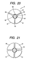
- the collet 6, as shown in Figs. 18 to 20, has a coned sleeve 69 which is split by slits 63 to form three jaws 61 arranged radially.
- the sleeve 69 has a heater holding hole 60 formed in the center of the bottom to define arc-shaped surfaces 62 curved with a curvature substantially equal to that of the periphery of the heater 10 for maximizing an area of contact with the periphery of the heater 10, thereby avoiding local concentration of pressure on the periphery of the heater 10 during insertion into the housing 5.
- the collet 6 may alternatively have four jaws 61, as shown in Fig. 21.
- the attachment of the heater 10 to the collect 6 is, as shown in Fig. 17, achieved by drawing the collet 6 into a jig 7 using the hydraulic pressure, for example, to squeeze the jaws 61, grasping the heater 10.
- a maximum pressure exerted by the collet 6 to force the heater 10 into the housing 5 depends upon the friction between the collet 6 and the metallic tube 11 and may be adjusted by controlling the pressure acting on the jaws 61 radially of the collet 6.
- the heater 10 held by the collet 6 is, as shown in Fig. 17, forced downward using a press machine (not shown) to bring the press fit wall 15 of the heater 10 into tight engagement with the small-diameter inner wall 55 of the housing 5.
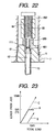
- Fig. 22 shows the second modification of the press-fitting operation to force the heater 10 into the housing 5 in the third embodiment.
- the collect 6 includes a push rod 68 producing additional pressure acting on the heater 10 during insertion into the housing 5.
- the push rod 68 includes a threaded portion 682 and a stem 689.
- the threaded portion 682 meshes with internal threads 64 formed in an inner wall of the collet 6.
- the stem 689 has a head 681 curved inwardly so as to fit with the round head 111 of the heater 10.
- the attachment of the heater 10 to the housing 5 is achieved in the following manner.
- the heater 10 is first held by the collet 6.
- the push rod 68 is screwed into the collet 6 until it is touched to the head 111 of the heater 10 without urging the heater 10 downward.
- a grasp of the heater 10 is so adjusted that a maximum friction between the collet 6 and the heater 10 will be F1 (i.e., 5 kN).
- a line A indicates a load transferred from the collet 6 to the heater 10
- a line B indicates a load transferred from the push rod 68 to the heater 10
- a line C indicates the sum of loads transferred from the collet 6 and the push rod 68.
- the load is applied to the heater 10 only from the collet 6, as shown by the line A.
- F1 that is the maximum friction between the collet 6 and the heater 10
- the heater 10 begins to slip so that it is urged against the head 681 of the push rod 68, thereby causing the load exerted by the push rod 68 on the heater 10 to be increased, as shown by the line B.
- the press operation is completed when the total load, as shown by the line C, reaches 10 kN.
- the press operation of this embodiment applies a load of 5 kN to the heater 10 through each of the collet 6 and the push rod 68.
- a load of 5 kN acts, in sequence, on different portions of the heater 10. This further reduces local concentration of pressure on the heater 10 during the press operation as compared with the above embodiments.
- Fig. 24 shows the third modification of the press-fitting operation to force the heater 10 into the housing 5 in the third embodiment.
- This modification uses first and second collets 65 and 66 which have formed therein central openings to define arc-shaped surfaces 652 and 662, respectively, similar to the collect 6 shown in Fig. 17.
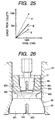
- the first and second collets 65 and 66 are disposed vertically at a given interval and apply different loads to the heater 10 downward in accordance with load lines shown in Fig. 25.
- a line D indicates a load transferred from the first collet 65 to the heater 10
- a line E indicates a load transferred from the second collet 66 to the heater 10
- a line F indicates the sum of loads transferred from the first and second collets 65 and 66.
- a radio of the load exerted from the first collet 65 on the heater 10 to the load exerted from the second collet 66 on the heater 10 is 1.3 : 1. Specifically, a greater load is provided by the first collet 65 located near the press fit wall 15 of the heater 10, while a smaller load is provided by the second collet 66 located far from the press fit wall 15, thereby avoiding bending or breakage of the heater 10 during the press-fitting operation.
- Fig. 26 shows the fourth modification of the press-fitting operation to force the heater 10 into the housing 5 in the third embodiment.
- the first collet 65 has a coned sleeve 69 which is, similar to the one shown in Fig. 18, split by slits to form jaws 651 arranged radially.
- the sleeve 69 has a heater holding hole 650 formed in the center of the bottom to define arc-shaped surfaces 652 curved outwardly with a curvature substantially equal to that of the periphery of the heater 10 for maximizing an area of contact with the periphery of the heater 10, thereby avoiding local concentration of pressure on the periphery of the heater 10 during insertion into the housing 5.
- the first collet 65 has formed therein a tapered bore 654 in alignment with the heater insertion hole 650 within which the second collet 66 is mounted.
- the second collet 66 like the first collet 65, has a coned sleeve 71 split by slits to form jaws 661 arranged radially.
- the sleeve 71 has a heater holding hole 660 formed in the center of the bottom to define arc-shaped surfaces 662 similar to the first collet 65 and also has a tapered outer surface 664 contouring an inner wall of the tapered bore 654 of the first collet 65.
- the first collect 65 is designed to be drawn into a jig 67 by hydraulic pressure to squeeze the jaws 651, grasping the heater 10 in tight engagement of the arc-shaped surfaces 652 with the periphery of the heater 10.
- the second collet 66 is designed to be forced into the tapered bore 654 of the first collet 65 by air or hydraulic pressure to squeeze the jaws 661, grasping a head portion of the heater 10.
- Downward loads applied from the first and second collets 65 and 66 to the heater 10 are adjusted by controlling the air and hydraulic pressures acting on the first and second collets 65 and 66 and may be determined similar to the third modification as described above.
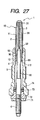
- Fig. 27 shows the fourth embodiment of the glow plug 1 which has a heater 10 different in structure from the ones in the above embodiments.
- the metallic tube 11 has formed thereon the press fit wall 15 whose diameter is substantially equal to that of a major portion of the metallic tube 11.
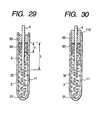
- a cylindrical sealing member 90 is disposed within the open end 112 of the metallic tube 11 which has the thickness T (3 mm in this embodiment), as shown in Fig. 29, smaller than the length L (20 mm in this embodiment) of a head portion of the central rod 4 embedded in the insulating powder 2.
- the metallic tube 11 and the central rod 4 to which the end 32 of the heating coil 3 is attached are first prepared.
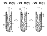
- the heating coil 3 is, as shown in Fig. 28(a), inserted into the metallic tube 11 and connected at the end 31 to the inner wall of the head 111 of the metallic tube 11 by plasma welding.
- the insulating powder 2 made of magnesia (MgO) is packed into the metallic tube 11 and subjected to vibrations to increase the density thereof.
- a sealing liquid 80 is, as shown in Fig. 28(b), put on the insulating powder 2 in the metallic tube 11.
- the sealing liquid 80 is an air-hardening, thermo-hardening, or ultraviolet-hardening liquid such as silicone rubber, fluoro rubber, acrylate resin, phloro silicone rubber, NBR rubbers, hydrin rubbers, and epoxy rubbers having a viscosity of 50 to 10000 St.
- This embodiment uses the liquid silicone rubber having a viscosity of 250 St.
- the sealing liquid 80 is left as it is at room temperature for 5 hours or more. This causes, as shown in Fig. 28(c), the sealing liquid 80 to permeate the insulating powder 2 and to be hardened, thereby forming the sealing member 90.
- the part of the sealing liquid 80 left on the insulating powder 2 is hardened as it is to form a sealing layer 85.
- the sealing member 90 and the sealing layer 85 serve to avoid entrance of air or oil into the metallic tube 11.
- the metallic tube 11 is swaged to decrease the diameter thereof to a desired value. This causes the density of the insulating powder 2 in the metallic tube 11 to be increased and the overall length of the metallic tube 11 to be prolonged with the result that the sealing member 90 and the sealing layer 85, as shown in Fig. 29, increase in thickness slightly. If the sealing layer 85 is, as shown in Fig. 30, forced out of the metallic tube 11, it may be either removed or left as it is.
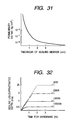
- Fig. 31 represents the permeability of the sealing member 90 measured for different values of thickness thereof.
- Fig. 32 represents the relation between depth of a portion of the insulating powder 2 into which the sealing liquid 80 penetrates (i.e., the thickness of the sealing member 90), which will be referred to as sealing liquid-penetrated depth below, and viscosity of the sealing liquid 80.
- sealing liquid-penetrated depth was measured for a given period of time for each type of sealing liquid. As can be seen from Fig. 32, the sealing liquid-penetrated depth for each type of sealing liquid will be constant after a certain period of time has lapsed. It is, thus, found that the adjustment of the thickness of the sealing member 90 may be achieved by changing the viscosity of the sealing liquid 80.
- the thickness T of the sealing member 90 in the structure shown in Fig. 27 be 0.5 mm or more in case where the sealing member 90 is made from liquid silicone rubber.
- Fig. 32 shows that the use of the sealing liquid 80 having a viscosity of 50 to 10000 St allows the sealing member 90 having a thickness of 0.5 mm or more to be formed.
- the glow plug includes a heater assembly which consists of a heater casing, a heating element, and a power supply rod.
- the heater casing has disposed therein the heating element connecting with the power supply rod and also has formed on a periphery thereof a press fit wall press-fitted into a hollow housing in tight engagement with an inner peripheral wall of the hollow housing.
- An uneven surface is formed on one of the press fit wall of the heater casing and the inner peripheral wall of the hollow housing.
- the uneven surface is patterned with lines such as fine grooves or ridges oriented at an angle relative to a longitudinal center line of the glow plug for forming barriers when the press fit wall is forced into the hollow housing which establish airtight seals between the heater casing and the hollow housing.
Landscapes
- Engineering & Computer Science (AREA)
- Chemical & Material Sciences (AREA)
- Combustion & Propulsion (AREA)
- Mechanical Engineering (AREA)
- General Engineering & Computer Science (AREA)
- Resistance Heating (AREA)
Claims (24)
- Glühkerze (1) mit:einem hohlen, eine gegebene Länge aufweisenden Gehäuse (5);einer Heizerbaugruppe (10), die ein Heizergehäuse (11), ein Heizelement (3), und eine Stromzufuhrstange (4) hat, wobei das Heizergehäuse (11) in sich vorgesehen das mit der Stromzufuhrstange (4) verbundene Heizelement (3) aufweist, und ebenfalls an einem seiner Randbereiche ausgebildet eine pressgepasste Wand (15) aufweist, die in festsitzendem Eingriff mit einer inneren Umfangswand (55) des hohlen Gehäuses (5) in das hohle Gehäuse eingepasst ist;
gekennzeichnet durcheine unebene Oberfläche (60), die entweder auf der pressgepassten Wand (15) des Heizergehäuses (11) oder auf der inneren Umfangswand (55) des hohlen Gehäuses (5) ausgebildet ist, wobei die unebene Oberfläche (60) auf sich ausgebildet ein Muster aufweist, das eine Länge aufweist, die an einem Winkel relativ zu einer Längs-Mittellinie der Glühkerze (1) orientiert ist. - Glühkerze (1) nach Anspruch 1, wobei die unebene Oberfläche (60) eine Oberflächenrauhigkeit von 25 µm oder weniger (Rz) aufweist.
- Glühkerze (1) nach Anspruch 1 oder 2, wobei die unebene Oberfläche (60) 20% oder mehr eines Bereiches von entweder der pressgepassten Wand (15) des Heizergehäuses (11) oder der inneren Umfangswand (55) des hohlen Gehäuses (5) einnimmt.
- Glühkerze (1) nach einem der Ansprüche 1 bis 3, wobei die unebene Oberfläche (60) mit Linien gemustert ist.
- Glühkerze (1) nach Anspruch 4, wobei die Linien der unebenen Oberfläche (60) in einem Winkel von 30 Grad oder mehr relativ zu der Längs-Mittellinie der Glühkerze (1) orientiert sind.
- Glühkerze (1) nach Anspruch 4, wobei die Linien der unebenen Oberfläche (60) entweder mit feinen Nuten oder Vorsprüngen ausgebildet sind.
- Glühkerze (1) nach einem der Ansprüche 1 bis 6, wobei die pressgepasste Wand (15) des Heizergehäuses (11) eine Härte aufweist, die von der der inneren Umfangswand (55) des hohlen Gehäuses (5) unterschiedlich ist.
- Glühkerze (1) nach einem der Ansprüche 1 bis 7, außerdem mit einem isolierenden Pulver (2), das innerhalb des Heizergehäuses (11) vorgesehen ist, um das Heizelement (3) von dem Heizergehäuse (11) zu isolieren und einem Dichtteil, wobei das Heizergehäuse (11) eine gegebene Länge aufweist und darin ausgebildet ein offenes Ende aufweist, die Stromzufuhrstange (4) teilweise durch das offene Ende des Heizergehäuses (11) in das isolierende Pulver (2) eingefügt ist, und das Dichtteil aus einer Dichtflüssigkeit hergestellt ist, die in einen Abschnitt des isolierenden Pulvers (2) eindringt, der dem offenen Ende des Heizergehäuses (11) ausgesetzt ist, und die gehärtet wird, um eine luftdichte Dichtung in dem offenen Ende des Heizergehäuses (11) auszubilden.
- Glühkerze (1) nach Anspruch 8, wobei die Dicke des Dichtteils kleiner ist als die Länge des Abschnitts der Stromzufuhrstange (4), die in das isolierende Pulver (2) eingebettet ist.
- Glühkerze (1) nach Anspruch 8 oder 9, wobei das Dichtteil eine Durchlässigkeit von 10 cm3/sek . kg/cm oder weniger aufweist.
- Glühkerze (1) nach einem der Ansprüche 8 bis 10, wobei das Dichtteil aus einem Silikonkautschuk hergestellt ist.
- Glühkerze (1) nach einem der Ansprüche 8 bis 11, wobei die Dicke des Dichtteils 0,5 mm oder mehr beträgt.
- Glühkerze (1) nach Anspruch 1, mit:dem Heizelement (3), das mit der Stromzufuhrstange (4) verbunden und teilweise durch ein offenes Ende in das Heizergehäuse (11) eingefügt ist;einem isolierenden Pulver (2), das innerhalb des Heizergehäuses (11) vorgesehen ist, um das Heizelement (3) von dem Heizergehäuse (11) zu isolieren; undeinem aus einer dichtenden Flüssigkeit hergestellten Dichtteil, das in einen Abschnitt des isolierenden Pulvers (2) eindringt, der dem offenen Ende des Heizergehäuses (11) ausgesetzt ist, und der gehärtet wird, um eine luftdichte Dichtung in dem offenen Ende des Heizergehäuses (11) auszubilden.
- Glühkerze nach Anspruch 13, wobei das Dichtteil eine Durchlässigkeit von 10 cm3/sek . kg/cm oder weniger aufweist.
- Glühkerzenherstellungsverfahren mit den Schritten:Vorbereiten eines hohlen Gehäuses (5), das eine gegebene Länge aufweist;Vorbereiten einer Heizerbaugruppe (10) mit einem Heizergehäuse (11) und einem Heizelement (3), das innerhalb des Heizergehäuses (11) vorgesehen ist, wobei das Heizergehäuse (11) eine pressgepasste Wand (15) an einem seiner Randbereiche ausgebildet aufweist;Zwingen des Heizergehäuses (11) der Heizerbaugruppe (10) in das hohle Gehäuse (5), um ein festsitzendes Eingreifen zwischen der pressgepassten Wand (15) des Heizergehäuses (11) und der inneren Umfangswand (55) des hohlen Gehäuses (5) einzuführen;
gekennzeichnet durch den SchrittBearbeiten von entweder der pressgepassten Wand (15) des Heizergehäuses (11) und der inneren Umfangswand (55) des hohlen Gehäuses (5), um so eine unebene Oberfläche (60) mit einem Muster auszubilden, das eine Länge aufweist, die in einem Winkel relativ zu einer Längs-Mittellinie des hohlen Gehäuses (5) orientiert ist. - Glühkerzenherstellungsverfahren nach Anspruch 15, wobei der Bearbeitungsschritt die unebene Oberfläche (60) mit Linien mustert, die entweder aus feinen Nuten oder aus Vorsprüngen ausgebildet sind.
- Glühkerzenherstellungsverfahren nach Anspruch 15, wobei der Zwangsschritt einen Ergreifungsschritt hat, bei dem ein Randbereich des Heizergehäuses (11) unter Verwendung einer Klemmbuchse (6) ergriffen wird, und einen Druckschritt, bei dem die Klemmbuchse (6) gedrückt wird, um das Heizergehäuse (11) der Heizerbaugruppe (10) in das hohle Gehäuse (5) zu zwingen.
- Glühkerzenherstellungsverfahren nach Anspruch 17, wobei der Zwangsschritt außerdem einen Montageschritt hat, bei dem vor dem Druckschritt das Heizergehäuse (11) ausgerichtet in dem hohlen Gehäuse (5) montiert wird.
- Glühkerzenherstellungsverfahren nach Anspruch 17, wobei der Zwangsschritt außerdem einen zweiten Druckschritt hat, bei dem ein Kopf des Heizergehäuses (11) unter Verwendung eines Druckteils gedrückt wird, nachdem eine auf das Heizergehäuse (11) von der Klemmbuchse (6) ausgeübte Last eine gegebene Höhe erreicht.
- Glühkerzenherstellungsverfahren nach Anspruch 15, wobei der Zwangsschritt einen Ergreifungsschritt hat, bei dem axial beabstandete Umfangsabschnitte des Heizergehäuses (11) unter Verwendung einer ersten und einer zweiten Klemmbuchse (65, 66) ergriffen werden, und einen Druckschritt, bei dem die erste beziehungsweise zweite Klemmbuchse unter unterschiedlichen Drücken gedrückt wird, um das Heizergehäuse (11) der Heizerbaugruppe (10) in das hohle Gehäuse (5) zu zwingen.
- Glühkerzenherstellungsverfahren nach Anspruch 15 mit den Schritten:Ergreifen eines Umfangs des Heizergehäuses (11) mit bogenförmigen Flächen von Klemmbacken einer Klemmbuchse (6); undDrücken der Klemmbuchse (6), um das Heizergehäuse (11) der Heizerbaugruppe (10) in das hohle Gehäuse (5) zu zwingen, um ein festsitzendes Eingreifen zwischen der druckgepassten Wand (15) des Heizergehäuses (11) und einer inneren Umfangswand (55) des hohlen Gehäuses (5) einzuführen.
- Glühkerzenherstellungsverfahren nach Anspruch 21, außerdem mit einem zweiten Druckschritt, bei dem ein Kopf des Heizergehäuses (11) unter Verwendung eines Druckteils gedrückt wird, nachdem eine von der Klemmbuchse (6) auf das Heizergehäuse (11) angewendete Last eine gegebene Höhe erreicht.
- Glühkerzenherstellungsverfahren nach Anspruch 21, wobei der Ergreifungsschritt axial beabstandete Umfangsabschnitte des Heizergehäuses (11) unter Verwendung einer ersten und einer zweiten Klemmbuchse (65, 66) ergreift, und wobei der Druckschritt die ersten beziehungsweise zweiten Klemmbuchsen (65, 66) unter unterschiedlichen Drücken drückt, um das Heizergehäuse (11) der Heizerbaugruppe (10) in das hohle Gehäuse (5) zu zwingen.
- Glühkerzenherstellungsverfahren nach Anspruch 15, dadurch gekennzeichnet, dass
beim Vorbereiten der Heizerbaugruppe (10) ein isolierendes Pulver (2) bereitgestellt ist, wobei das isolierende Pulver (2) innerhalb des Heizerrohrs vorgesehen ist, um das Heizelement (3) von dem Heizerrohr zu isolieren; mit dem Schritt, bei dem eine Dichtflüssigkeit in einen Abschnitt des isolierenden Pulvers (2) eindringt, der dem offenen Ende des Heizerrohrs ausgesetzt ist, und Härten der Dichtflüssigkeit, um eine luftdichte Dichtung in dem offenen Ende des Heizergehäuses (11) auszubilden; Reduzieren des Heizerrohrs, um dessen Durchmesser zu verringern, und
Zwingen des Heizerrohrs in das hohle Gehäuse (5), um ein festsitzendes Eingreifen zwischen der druckgepassten Wand (15) des Heizerrohrs und der inneren Umfangswand (55) des hohlen Gehäuses (5) einzuführen.
Priority Applications (1)
| Application Number | Priority Date | Filing Date | Title |
|---|---|---|---|
| EP04008758A EP1441179A3 (de) | 1997-09-19 | 1998-09-18 | Glühkerze |
Applications Claiming Priority (12)
| Application Number | Priority Date | Filing Date | Title |
|---|---|---|---|
| JP27355397A JP3885311B2 (ja) | 1997-09-19 | 1997-09-19 | グロープラグ及びその製造方法 |
| JP27355197A JPH1194251A (ja) | 1997-09-19 | 1997-09-19 | グロープラグ及びその製造方法 |
| JP27355397 | 1997-09-19 | ||
| JP27355297A JP3843557B2 (ja) | 1997-09-19 | 1997-09-19 | グロープラグ及びその製造方法 |
| JP273551/97 | 1997-09-19 | ||
| JP273553/97 | 1997-09-19 | ||
| JP27355497A JP3758332B2 (ja) | 1997-09-19 | 1997-09-19 | グロープラグの製造方法 |
| JP27355497 | 1997-09-19 | ||
| JP27355197 | 1997-09-19 | ||
| JP27355297 | 1997-09-19 | ||
| JP273552/97 | 1997-09-19 | ||
| JP273554/97 | 1997-09-19 |
Related Child Applications (1)
| Application Number | Title | Priority Date | Filing Date |
|---|---|---|---|
| EP04008758A Division EP1441179A3 (de) | 1997-09-19 | 1998-09-18 | Glühkerze |
Publications (3)
| Publication Number | Publication Date |
|---|---|
| EP0903541A2 EP0903541A2 (de) | 1999-03-24 |
| EP0903541A3 EP0903541A3 (de) | 2001-04-18 |
| EP0903541B1 true EP0903541B1 (de) | 2004-11-17 |
Family
ID=27478995
Family Applications (2)
| Application Number | Title | Priority Date | Filing Date |
|---|---|---|---|
| EP19980117773 Expired - Lifetime EP0903541B1 (de) | 1997-09-19 | 1998-09-18 | Glühkerze |
| EP04008758A Withdrawn EP1441179A3 (de) | 1997-09-19 | 1998-09-18 | Glühkerze |
Family Applications After (1)
| Application Number | Title | Priority Date | Filing Date |
|---|---|---|---|
| EP04008758A Withdrawn EP1441179A3 (de) | 1997-09-19 | 1998-09-18 | Glühkerze |
Country Status (2)
| Country | Link |
|---|---|
| EP (2) | EP0903541B1 (de) |
| DE (1) | DE69827571T2 (de) |
Families Citing this family (9)
| Publication number | Priority date | Publication date | Assignee | Title |
|---|---|---|---|---|
| DE10130488B4 (de) * | 2000-06-26 | 2011-07-21 | DENSO CORPORATION, Aichi-pref. | Glühkerze |
| DE10041282B4 (de) * | 2000-08-22 | 2005-02-10 | Beru Ag | Verfahren zur Verbindung eines Heizstabes einer Glühkerze mit ihrem Glühkerzenkörper und eine entsprechende Glühkerze |
| DE60228021D1 (de) * | 2001-05-28 | 2008-09-18 | Ngk Spark Plug Co | Heizung und Glühkerze |
| DE10140183A1 (de) * | 2001-08-22 | 2003-03-13 | Beru Ag | Wasservorwärmstutzen |
| JP4087303B2 (ja) | 2002-07-19 | 2008-05-21 | 日本特殊陶業株式会社 | グロープラグの製造方法およびグロープラグの製造装置 |
| JP5102530B2 (ja) * | 2006-05-19 | 2012-12-19 | 日本特殊陶業株式会社 | グロープラグ及びその製造方法 |
| DE102009048643B4 (de) * | 2009-09-30 | 2013-11-28 | Borgwarner Beru Systems Gmbh | Glühkerze und Verfahren zum Verbinden eines Stifts aus einer Funktionskeramik mit einer Metallhülse |
| JP6567677B2 (ja) | 2015-09-17 | 2019-08-28 | 日立オートモティブシステムズ株式会社 | 内燃機関のバルブタイミング制御装置 |
| CN116817148B (zh) * | 2023-08-30 | 2023-11-03 | 沈阳华钛实业有限公司 | 一种机匣内端面检测装置及检测方法 |
Family Cites Families (5)
| Publication number | Priority date | Publication date | Assignee | Title |
|---|---|---|---|---|
| JPS5952726B2 (ja) * | 1981-06-24 | 1984-12-21 | 日本特殊陶業株式会社 | シ−ズ型グロ−プラグの取付金具にグロ−チュ−ブを接合する方法 |
| WO1983001093A1 (en) * | 1981-09-25 | 1983-03-31 | Bailey, John, M. | Glow plug having resiliently mounted ceramic surface-ignition element |
| JP2537228B2 (ja) * | 1987-04-16 | 1996-09-25 | 日本特殊陶業株式会社 | シ−ズグロ−プラグ |
| JPS6446520A (en) * | 1987-08-12 | 1989-02-21 | Nippon Denso Co | Resistance device for preheating plug of diesel engine |
| JP2890325B2 (ja) * | 1990-07-23 | 1999-05-10 | 日本特殊陶業株式会社 | シーズ型グロープラグの製造方法 |
-
1998
- 1998-09-18 DE DE69827571T patent/DE69827571T2/de not_active Expired - Lifetime
- 1998-09-18 EP EP19980117773 patent/EP0903541B1/de not_active Expired - Lifetime
- 1998-09-18 EP EP04008758A patent/EP1441179A3/de not_active Withdrawn
Also Published As
| Publication number | Publication date |
|---|---|
| EP1441179A3 (de) | 2011-05-18 |
| DE69827571D1 (de) | 2004-12-23 |
| DE69827571T2 (de) | 2006-01-05 |
| EP0903541A2 (de) | 1999-03-24 |
| EP1441179A2 (de) | 2004-07-28 |
| EP0903541A3 (de) | 2001-04-18 |
Similar Documents
| Publication | Publication Date | Title |
|---|---|---|
| US5087147A (en) | Assembly of shaft and hub member | |
| EP0903541B1 (de) | Glühkerze | |
| US5493776A (en) | Method of installing valve guide insert | |
| US6289921B1 (en) | Hydraulic valve, especially for controlling a camshaft movement in a motor vehicle | |
| KR910004978B1 (ko) | 한단에 플랜지를 구비한 하우징과 이 하우징에 압입된 베어링부시를 포함하는 베어링장치의 제조방법 | |
| EP0404570A3 (de) | Verfahren zur Herstellung eines Hohlkörpers | |
| US20020162412A1 (en) | Rack and pinion steering gear with a unitized yoke assembly | |
| GB2349190A (en) | A method of manufacturing a common rail | |
| US5927912A (en) | Composite drill bit using adhesive bond | |
| US5664530A (en) | Tappet for a valve drive of an internal combustion engine | |
| CN1212339A (zh) | 扩张销钉 | |
| KR100810042B1 (ko) | 가열 로드와 글로우 플러그의 동체를 접합하는 방법 | |
| US6792786B2 (en) | Fabrication method of metal shell of spark plug | |
| US6030157A (en) | Composite drill bit using adhesive bond | |
| US7172483B2 (en) | Method of making metallic shell for spark plug, method of making spark plug having metallic shell and spark plug produced by the same | |
| JP3758332B2 (ja) | グロープラグの製造方法 | |
| US4987672A (en) | Method of partitioning the internal space of a hollow cylindrical member | |
| EP1158245A1 (de) | Glühkerze für Dieselmotoren und Verfahren zum Herstellen derselben | |
| CA2185714C (en) | Valve guide insert | |
| JPH1194252A (ja) | グロープラグ及びその製造方法 | |
| US6497040B1 (en) | Process for producing an angled bore in a component | |
| RU94016578A (ru) | Наконечник для сварочной горелки и способ его изготовления | |
| JPH1194251A (ja) | グロープラグ及びその製造方法 | |
| JPH10141172A (ja) | コモンレールの製造方法 | |
| NZ272318A (en) | Valve guide insertion tool for guide with constant wall thickness but tapered insertion ends: tool has frusto-conical junction engaging non-bore end of guide |
Legal Events
| Date | Code | Title | Description |
|---|---|---|---|
| PUAI | Public reference made under article 153(3) epc to a published international application that has entered the european phase |
Free format text: ORIGINAL CODE: 0009012 |
|
| AK | Designated contracting states |
Kind code of ref document: A2 Designated state(s): DE FR GB IT |
|
| AX | Request for extension of the european patent |
Free format text: AL;LT;LV;MK;RO;SI |
|
| PUAL | Search report despatched |
Free format text: ORIGINAL CODE: 0009013 |
|
| AK | Designated contracting states |
Kind code of ref document: A3 Designated state(s): AT BE CH CY DE DK ES FI FR GB GR IE IT LI LU MC NL PT SE |
|
| AX | Request for extension of the european patent |
Free format text: AL;LT;LV;MK;RO;SI |
|
| 17P | Request for examination filed |
Effective date: 20010508 |
|
| AKX | Designation fees paid |
Free format text: DE FR GB IT |
|
| 17Q | First examination report despatched |
Effective date: 20031113 |
|
| GRAP | Despatch of communication of intention to grant a patent |
Free format text: ORIGINAL CODE: EPIDOSNIGR1 |
|
| GRAS | Grant fee paid |
Free format text: ORIGINAL CODE: EPIDOSNIGR3 |
|
| GRAA | (expected) grant |
Free format text: ORIGINAL CODE: 0009210 |
|
| AK | Designated contracting states |
Kind code of ref document: B1 Designated state(s): DE FR GB IT |
|
| REG | Reference to a national code |
Ref country code: GB Ref legal event code: FG4D |
|
| REF | Corresponds to: |
Ref document number: 69827571 Country of ref document: DE Date of ref document: 20041223 Kind code of ref document: P |
|
| ET | Fr: translation filed | ||
| PLBE | No opposition filed within time limit |
Free format text: ORIGINAL CODE: 0009261 |
|
| STAA | Information on the status of an ep patent application or granted ep patent |
Free format text: STATUS: NO OPPOSITION FILED WITHIN TIME LIMIT |
|
| 26N | No opposition filed |
Effective date: 20050818 |
|
| PGFP | Annual fee paid to national office [announced via postgrant information from national office to epo] |
Ref country code: FR Payment date: 20110922 Year of fee payment: 14 Ref country code: GB Payment date: 20110914 Year of fee payment: 14 |
|
| PGFP | Annual fee paid to national office [announced via postgrant information from national office to epo] |
Ref country code: IT Payment date: 20110920 Year of fee payment: 14 |
|
| GBPC | Gb: european patent ceased through non-payment of renewal fee |
Effective date: 20120918 |
|
| REG | Reference to a national code |
Ref country code: FR Ref legal event code: ST Effective date: 20130531 |
|
| PG25 | Lapsed in a contracting state [announced via postgrant information from national office to epo] |
Ref country code: GB Free format text: LAPSE BECAUSE OF NON-PAYMENT OF DUE FEES Effective date: 20120918 |
|
| PG25 | Lapsed in a contracting state [announced via postgrant information from national office to epo] |
Ref country code: IT Free format text: LAPSE BECAUSE OF NON-PAYMENT OF DUE FEES Effective date: 20120918 Ref country code: FR Free format text: LAPSE BECAUSE OF NON-PAYMENT OF DUE FEES Effective date: 20121001 |
|
| PGFP | Annual fee paid to national office [announced via postgrant information from national office to epo] |
Ref country code: DE Payment date: 20170928 Year of fee payment: 20 |
|
| REG | Reference to a national code |
Ref country code: DE Ref legal event code: R071 Ref document number: 69827571 Country of ref document: DE |