EP0903522B1 - Antrieb mit elektrostrictiver Bremsvorrichtung - Google Patents
Antrieb mit elektrostrictiver Bremsvorrichtung Download PDFInfo
- Publication number
- EP0903522B1 EP0903522B1 EP98115071A EP98115071A EP0903522B1 EP 0903522 B1 EP0903522 B1 EP 0903522B1 EP 98115071 A EP98115071 A EP 98115071A EP 98115071 A EP98115071 A EP 98115071A EP 0903522 B1 EP0903522 B1 EP 0903522B1
- Authority
- EP
- European Patent Office
- Prior art keywords
- actuator
- output coupler
- driving element
- external device
- brake device
- Prior art date
- Legal status (The legal status is an assumption and is not a legal conclusion. Google has not performed a legal analysis and makes no representation as to the accuracy of the status listed.)
- Expired - Lifetime
Links
- 230000003213 activating effect Effects 0.000 claims description 2
- 239000000919 ceramic Substances 0.000 claims description 2
- 230000015572 biosynthetic process Effects 0.000 claims 4
- 238000005755 formation reaction Methods 0.000 claims 4
- 230000008878 coupling Effects 0.000 description 6
- 238000010168 coupling process Methods 0.000 description 6
- 238000005859 coupling reaction Methods 0.000 description 6
- 239000000779 smoke Substances 0.000 description 4
- 238000010586 diagram Methods 0.000 description 2
- 238000000034 method Methods 0.000 description 2
- 206010010904 Convulsion Diseases 0.000 description 1
- 238000004378 air conditioning Methods 0.000 description 1
- 238000007599 discharging Methods 0.000 description 1
- 238000010438 heat treatment Methods 0.000 description 1
- 238000009434 installation Methods 0.000 description 1
- 239000000463 material Substances 0.000 description 1
- 230000002265 prevention Effects 0.000 description 1
- 230000002035 prolonged effect Effects 0.000 description 1
- 230000001360 synchronised effect Effects 0.000 description 1
- 230000001052 transient effect Effects 0.000 description 1
Images
Classifications
-
- F—MECHANICAL ENGINEERING; LIGHTING; HEATING; WEAPONS; BLASTING
- F16—ENGINEERING ELEMENTS AND UNITS; GENERAL MEASURES FOR PRODUCING AND MAINTAINING EFFECTIVE FUNCTIONING OF MACHINES OR INSTALLATIONS; THERMAL INSULATION IN GENERAL
- F16K—VALVES; TAPS; COCKS; ACTUATING-FLOATS; DEVICES FOR VENTING OR AERATING
- F16K31/00—Actuating devices; Operating means; Releasing devices
- F16K31/004—Actuating devices; Operating means; Releasing devices actuated by piezoelectric means
-
- F—MECHANICAL ENGINEERING; LIGHTING; HEATING; WEAPONS; BLASTING
- F16—ENGINEERING ELEMENTS AND UNITS; GENERAL MEASURES FOR PRODUCING AND MAINTAINING EFFECTIVE FUNCTIONING OF MACHINES OR INSTALLATIONS; THERMAL INSULATION IN GENERAL
- F16K—VALVES; TAPS; COCKS; ACTUATING-FLOATS; DEVICES FOR VENTING OR AERATING
- F16K31/00—Actuating devices; Operating means; Releasing devices
- F16K31/02—Actuating devices; Operating means; Releasing devices electric; magnetic
- F16K31/04—Actuating devices; Operating means; Releasing devices electric; magnetic using a motor
- F16K31/047—Actuating devices; Operating means; Releasing devices electric; magnetic using a motor characterised by mechanical means between the motor and the valve, e.g. lost motion means reducing backlash, clutches, brakes or return means
Definitions
- Document EP295 770A discloses a vehicle brake using piezolelectric elements which are connected together to produce a braking force.
- the torque transmitting device is cooperatively engaged to and is located between the driving device and the output coupling.
- a retracting device is configured for exerting a retracting force to return the external device to the default position via the transmitting device when the power is removed from the actuator.
- An important feature of the invention is a piezoelectric braking device which exerts a braking force on the driving device. The braking force exceeds the retracting force exerted by the retracting device when the braking device is activated, but is extinguished when the braking device is deactivated.
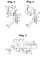
- the beam 60 When the circuit 74 is placed in this configuration, the beam 60 activates and bends towards the flywheel 68 to lock onto the notches 70 (best seen in FIG. 4). The beam 60 cannot discharge through the diodes 78, 80 because they are effectively eliminated from the circuit 74 when the switch 54 is in position B.
Landscapes
- Engineering & Computer Science (AREA)
- General Engineering & Computer Science (AREA)
- Mechanical Engineering (AREA)
- Braking Arrangements (AREA)
- Air-Flow Control Members (AREA)
- Connection Of Motors, Electrical Generators, Mechanical Devices, And The Like (AREA)
- Respiratory Apparatuses And Protective Means (AREA)
- Electrically Driven Valve-Operating Means (AREA)
- General Electrical Machinery Utilizing Piezoelectricity, Electrostriction Or Magnetostriction (AREA)
Claims (9)
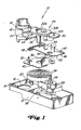
- Elektro-mechanische Betätigungseinheit (10) zum Halten einer externen Vorrichtung, an die die Betätigungseinheit (10) angeschlossen ist, in einer Betriebsposition, wenn Strom an der Betätigungseinheit (10) anliegt, und zum Ermöglichen, dass die externe Vorrichtung in eine Fehlerposition zurückkehrt, wenn die Stromzufuhr gestoppt wird, mit
einem Gehäuse (12);
einer Ausgangskupplung (14), die drehbar am Gehäuse (12) montiert und an die externe Vorrichtung angeschlossen ist sowie die externe Vorrichtung zwischen der Betriebsposition und der Fehlerposition verschieben kann;
einem elektromechanischen Antriebselement (28), das im Gehäuse (12) montiert ist, um die Ausgangskupplung (14) mit einem Drehmoment zu beaufschlagen und dadurch die externe Vorrichtung zwischen der Fehlerposition und der Betriebsposition zu verschieben, wenn das elektromechanische Antriebselement (28) aktiviert wird;
einem Getriebezug (24) zum Übertragen und Ändern des Drehmomentes vom Antriebselement (28) auf die Ausgangskupplung (14), wobei der Getriebezug (24) zwischen dem elektromechanischen Antriebselement (28) und der Ausgangskupplung (14) angeordnet ist und mit diesen in Eingriff steht;
einer Rückzugfeder (38), die mit dem Getriebezug (24) in Verbindung steht und eine Rückzugkraft ausübt, um die externe Vorrichtung in die Fehlerposition über den Getriebezug (24) zurückzuziehen, wenn die Stromzufuhr zur elektro-mechanischen Betätigungseinheit (10) gestoppt wird;
einem Verriegelungselement (689, das mit dem elektromechanischen Antriebselement (28) verbunden ist und Gestaltungen (70) besitzt; und
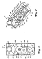
einer Bremsvorrichtung (58) zum Halten der Ausgangskupplung (14) in der Betriebsposition gegen die von der Rückzugfeder (38) ausgeübte Rückzugkraft, wobei die Bremsvorrichtung (58) eine stationäre Montageeinrichtung (62) und einen elektrostriktiven oder piezoelektrischen Träger (60) aufweist;
wobei der Träger (60) ein erstes Ende, das an der Montageeinrichtung (62) befestigt ist, und ein zweites Ende besitzt, das so angeordnet und ausgebildet ist, dass es sich mit den Gestaltungen (70) verriegelt, wenn die Bremsvorrichtung (58) aktiviert wird, und das Verriegelungselement (68) freigibt, wenn die Bremsvorrichtung (58) deaktiviert wird. - Betätigungseinheit nach Anspruch 1, bei der die Gestaltungen (70) Kerben sind.
- Betätigungseinheit nach Anspruch 1, bei der die Gestaltungen (70) Vorsprünge sind.
- Betätigungseinheit nach Anspruch 1, die des weiteren einen Schalter (54) zum Aberregen des elektromechanischen Antriebselementes (28) und zum Aktivieren der Bremsvorrichtung (58), wenn der Schalter (54) erregt wird, aufweist.
- Betätigungseinheit nach Anspruch 4, bei der der Schalter (54) ein Mikroschalter ist.
- Betätigungseinheit nach einem der vorangehenden Ansprüche, die des weiteren eine Drehplatte (42) besitzt, die drehbar am elektromechanischen Antriebselement (28) befestigt und so ausgebildet ist, dass sie den Schalter (54) erregt, wenn die Ausgangskupplung (14) die Betriebsposition erreicht.
- Betätigungseinheit nach Anspruch 1, bei der die Rückzugfeder (38) eine Spiralfeder ist.
- Betätigungseinheit nach Anspruch 1, bei der der e-lektrostriktive oder piezoelektrische Träger (60) mindestens einen piezoelektrischen keramischen Streifen aufweist.
- Betätigungseinheit nach Anspruch 1, bei der die Bremsvorrichtung (58) von einer Steuerschaltung (74) aktiviert wird, die eine Spannung an den elektrostriktiven oder piezoelektrischen Träger (60) zum Ablenken des zweiten Endes in Richtung auf das Verriegelungselement (68) legt.
Applications Claiming Priority (2)
| Application Number | Priority Date | Filing Date | Title |
|---|---|---|---|
| US08/914,519 US5986369A (en) | 1997-08-19 | 1997-08-19 | Actuator having piezoelectric braking element |
| US914519 | 1997-08-19 |
Publications (3)
| Publication Number | Publication Date |
|---|---|
| EP0903522A2 EP0903522A2 (de) | 1999-03-24 |
| EP0903522A3 EP0903522A3 (de) | 2001-01-31 |
| EP0903522B1 true EP0903522B1 (de) | 2005-05-04 |
Family
ID=25434471
Family Applications (1)
| Application Number | Title | Priority Date | Filing Date |
|---|---|---|---|
| EP98115071A Expired - Lifetime EP0903522B1 (de) | 1997-08-19 | 1998-08-11 | Antrieb mit elektrostrictiver Bremsvorrichtung |
Country Status (11)
| Country | Link |
|---|---|
| US (1) | US5986369A (de) |
| EP (1) | EP0903522B1 (de) |
| JP (1) | JP4171110B2 (de) |
| KR (1) | KR100544391B1 (de) |
| CN (1) | CN1102857C (de) |
| AU (1) | AU732836B2 (de) |
| CA (1) | CA2237248C (de) |
| DE (1) | DE69830031T2 (de) |
| IL (1) | IL125565A0 (de) |
| NZ (1) | NZ331168A (de) |
| TW (1) | TW434981B (de) |
Cited By (2)
| Publication number | Priority date | Publication date | Assignee | Title |
|---|---|---|---|---|
| WO2010008398A1 (en) * | 2008-07-18 | 2010-01-21 | Flowserve Management Company | Variable speed actuator |
| US10094485B2 (en) | 2008-07-18 | 2018-10-09 | Flowserve Management Company | Variable-speed actuator |
Families Citing this family (29)
| Publication number | Priority date | Publication date | Assignee | Title |
|---|---|---|---|---|
| US5986369A (en) * | 1997-08-19 | 1999-11-16 | Siemens Building Technologies, Inc. | Actuator having piezoelectric braking element |
| US6178369B1 (en) * | 1998-01-30 | 2001-01-23 | Continental Teves Ag & Co., Ohg | Method and regulating system for applying defined actuating forces |
| US6651952B1 (en) * | 1998-11-12 | 2003-11-25 | Barber Colman Company | Two position rotary actuator incorporating DC solenoid |
| US6097123A (en) * | 1999-06-03 | 2000-08-01 | Johnson Controls Technology Company | Brake and stall detector for a motorized actuator |
| EP1368230A4 (de) * | 2001-03-15 | 2005-04-13 | Stoneridge Control Devices Inc | Stellantrieb mit integrierten kolben-positions-regelsystem |
| DE10133630A1 (de) * | 2001-07-11 | 2003-01-30 | Siemens Ag | Elektromotorischer Antrieb |
| US6679356B2 (en) * | 2002-01-23 | 2004-01-20 | Delphi Technologies, Inc. | Brake caliper backdrive apparatus and method |
| US7021415B2 (en) * | 2002-02-01 | 2006-04-04 | Stoneridge Control Devices, Inc. | Electro-mechanical actuator for an electrically actuated parking brake |
| US6725976B2 (en) * | 2002-03-20 | 2004-04-27 | Invensys Building Systems Inc. | Manual override and locking mechanism and actuator including same |
| US7066301B2 (en) | 2002-03-20 | 2006-06-27 | Invensys Building Systems, Inc. | Linear actuator having manual override and locking mechanism |
| DE60325772D1 (de) * | 2002-11-13 | 2009-02-26 | Stoneridge Control Devices Inc | Elektromechanisches stellglied für eine elektrisch betätigte feststellbremse |
| US7021072B2 (en) | 2003-04-24 | 2006-04-04 | Honeywell International Inc. | Current control loop for actuator and method |
| US6979965B2 (en) * | 2003-04-24 | 2005-12-27 | Honeywell International Inc. | Spring return actuator for a damper |
| GB2425160B (en) * | 2005-04-12 | 2010-11-17 | Perpetuum Ltd | An Electromechanical Generator for, and method of, Converting Mechanical Vibrational Energy into Electrical Energy |
| US20060272444A1 (en) * | 2005-06-03 | 2006-12-07 | Ray Cockerham | Electromechanical cable actuator assembly controller |
| DE102005038426A1 (de) * | 2005-08-16 | 2007-02-22 | Wilo Ag | Ventil mit Piezoelement |
| GB0613662D0 (en) * | 2006-07-10 | 2006-08-16 | Rotork Controls | Improvements to valve actuators |
| KR100734394B1 (ko) * | 2006-09-07 | 2007-07-02 | 주식회사 은하양행 | 스프링 리턴 밸브 액추에이터 |
| US20100056039A1 (en) * | 2007-04-12 | 2010-03-04 | Belimo Holding Ag | Drive system for a fire protection flap |
| US8587170B2 (en) | 2008-05-21 | 2013-11-19 | Siemens Industry, Inc. | Actuator arrangement with worm gear and rotational output having an encoder |
| JP5376115B2 (ja) * | 2008-08-27 | 2013-12-25 | ミツミ電機株式会社 | 駆動装置の駆動方法 |
| US8084982B2 (en) | 2008-11-18 | 2011-12-27 | Honeywell International Inc. | HVAC actuator with output torque compensation |
| US8084980B2 (en) | 2009-01-30 | 2011-12-27 | Honeywell International Inc. | HVAC actuator with internal heating |
| FR2979410B1 (fr) | 2011-08-23 | 2013-08-23 | Valeo Sys Controle Moteur Sas | Vanne, notamment pour circuit d'admission de moteur d'automobile, comportant un moyen d'entrainement en retour d'un volet obturateur en cas de defaillance du moyen de rappel |
| GB2514374A (en) * | 2013-05-21 | 2014-11-26 | Johnson Electric Sa | Electrically operated valve assembly |
| JP6571395B2 (ja) * | 2015-05-29 | 2019-09-04 | 日本電産サンキョー株式会社 | ダンパ装置 |
| WO2021228780A1 (en) | 2020-05-11 | 2021-11-18 | Rotiny Aps | Actuator for fluid flow controllers |
| CN112161096B (zh) * | 2020-10-27 | 2025-01-07 | 泰州市都瑞堡船舶设备有限公司 | 一种能迅速关闭的电动风闸 |
| DE102021209914B3 (de) | 2021-09-08 | 2022-10-13 | Siemens Schweiz Ag | Stellantrieb mit einer elektrisch ein- und ausschaltbaren, berührungsfrei arbeitenden magnetischen Rastmomenthemmung zum Halten oder Lösen eines Rotorbechers eines Stellantriebmotors |
Family Cites Families (29)
| Publication number | Priority date | Publication date | Assignee | Title |
|---|---|---|---|---|
| US3192416A (en) * | 1963-07-16 | 1965-06-29 | Hoover Co | Synchronous motor with limit control |
| US3302043A (en) * | 1963-07-16 | 1967-01-31 | Hoover Co | Synchronous electric motor |
| US3297889A (en) * | 1964-01-15 | 1967-01-10 | Breskend Sam | Clock driver |
| US3808895A (en) * | 1973-02-09 | 1974-05-07 | J Fitzwater | Electric fail-safe actuator |
| JPS5245299U (de) * | 1975-09-27 | 1977-03-30 | ||
| JPS575644U (de) * | 1980-06-11 | 1982-01-12 | ||
| US4623044A (en) * | 1983-12-22 | 1986-11-18 | Jidosha Kiki Co., Ltd. | Brake apparatus |
| US4602702A (en) * | 1983-12-28 | 1986-07-29 | Jidosha Kiki Co., Ltd. | Brake apparatus |
| US4689516A (en) * | 1985-05-02 | 1987-08-25 | Kabushiki Kaisha Toshiba | Position adjustment device with a piezoelectric element as a lock mechanism |
| US4581987A (en) * | 1985-05-30 | 1986-04-15 | Ecm Motor Co. | Fire damper actuator |
| JPS6283521A (ja) * | 1985-10-09 | 1987-04-17 | Nippon Electric Ind Co Ltd | 圧電型摩擦ブレ−キ |
| US4621789A (en) * | 1985-11-04 | 1986-11-11 | Rikuo Fukamachi | Electrically driven valve |
| US4669578A (en) * | 1986-03-13 | 1987-06-02 | Rikuo Fukamachi | Motor driven valve |
| DE3608550A1 (de) * | 1986-03-14 | 1987-09-17 | Festo Kg | Piezo-elektrisch betaetigbares ventil |
| JPS6338779A (ja) * | 1986-07-31 | 1988-02-19 | Keihin Seiki Mfg Co Ltd | 電動弁 |
| US4741508A (en) * | 1987-04-13 | 1988-05-03 | Rikuo Fukamachi | Actuator for valve |
| CA1319331C (en) * | 1987-04-17 | 1993-06-22 | Kouhei Yamatoh | Brake device |
| JPH0511385Y2 (de) * | 1988-05-30 | 1993-03-22 | ||
| US4890027A (en) * | 1988-11-21 | 1989-12-26 | Hughes Aircraft Company | Dynamic motor controller |
| JPH02126670U (de) * | 1989-03-28 | 1990-10-18 | ||
| US5090518A (en) * | 1990-05-31 | 1992-02-25 | General Motors Corporation | Brake control system |
| JPH05277200A (ja) * | 1992-04-16 | 1993-10-26 | Kuken Denki Kk | 防火用ダンパの開閉装置 |
| JPH0738844U (ja) * | 1993-12-20 | 1995-07-14 | 株式会社松井製作所 | 電源が切れた際に作動するバルブ |
| JP3058813B2 (ja) * | 1994-07-04 | 2000-07-04 | セイコーエプソン株式会社 | 発電装置およびその制御方法 |
| JPH0861404A (ja) * | 1994-08-18 | 1996-03-08 | Ogura Clutch Co Ltd | 負作動形電磁ブレーキ |
| US5498143A (en) * | 1994-12-15 | 1996-03-12 | Tecumseh Products Company | Scroll compressor with flywheel |
| JPH08208378A (ja) * | 1995-02-02 | 1996-08-13 | Komatsu Ltd | 単結晶引上げ機の送り駆動装置 |
| JP3033881U (ja) * | 1996-07-22 | 1997-02-07 | 大東テック株式会社 | モータダンパ |
| US5986369A (en) * | 1997-08-19 | 1999-11-16 | Siemens Building Technologies, Inc. | Actuator having piezoelectric braking element |
-
1997
- 1997-08-19 US US08/914,519 patent/US5986369A/en not_active Expired - Lifetime
-
1998
- 1998-05-08 CA CA002237248A patent/CA2237248C/en not_active Expired - Lifetime
- 1998-07-28 AU AU78544/98A patent/AU732836B2/en not_active Expired
- 1998-07-28 NZ NZ331168A patent/NZ331168A/en unknown
- 1998-07-29 IL IL12556598A patent/IL125565A0/xx unknown
- 1998-08-11 DE DE69830031T patent/DE69830031T2/de not_active Expired - Lifetime
- 1998-08-11 EP EP98115071A patent/EP0903522B1/de not_active Expired - Lifetime
- 1998-08-11 TW TW087112274A patent/TW434981B/zh not_active IP Right Cessation
- 1998-08-18 JP JP23163798A patent/JP4171110B2/ja not_active Expired - Lifetime
- 1998-08-18 KR KR1019980033460A patent/KR100544391B1/ko not_active Expired - Lifetime
- 1998-08-19 CN CN98118455A patent/CN1102857C/zh not_active Expired - Lifetime
Cited By (3)
| Publication number | Priority date | Publication date | Assignee | Title |
|---|---|---|---|---|
| WO2010008398A1 (en) * | 2008-07-18 | 2010-01-21 | Flowserve Management Company | Variable speed actuator |
| US9188237B2 (en) | 2008-07-18 | 2015-11-17 | Flowserve Management Company | Variable-speed actuator |
| US10094485B2 (en) | 2008-07-18 | 2018-10-09 | Flowserve Management Company | Variable-speed actuator |
Also Published As
| Publication number | Publication date |
|---|---|
| CA2237248C (en) | 2001-02-27 |
| AU732836B2 (en) | 2001-05-03 |
| DE69830031D1 (de) | 2005-06-09 |
| DE69830031T2 (de) | 2006-01-19 |
| CN1221637A (zh) | 1999-07-07 |
| EP0903522A2 (de) | 1999-03-24 |
| JP4171110B2 (ja) | 2008-10-22 |
| CN1102857C (zh) | 2003-03-12 |
| IL125565A0 (en) | 1999-03-12 |
| KR100544391B1 (ko) | 2006-05-09 |
| AU7854498A (en) | 1999-03-04 |
| NZ331168A (en) | 1998-09-24 |
| JPH11137705A (ja) | 1999-05-25 |
| US5986369A (en) | 1999-11-16 |
| EP0903522A3 (de) | 2001-01-31 |
| CA2237248A1 (en) | 1999-02-19 |
| TW434981B (en) | 2001-05-16 |
| HK1023732A1 (en) | 2000-09-22 |
| KR19990023679A (ko) | 1999-03-25 |
Similar Documents
| Publication | Publication Date | Title |
|---|---|---|
| EP0903522B1 (de) | Antrieb mit elektrostrictiver Bremsvorrichtung | |
| EP0944788B1 (de) | Linear antrieb | |
| US6177771B1 (en) | Automatic door operator | |
| EP1347249B1 (de) | Überlagerter Handbetätigungs- und Verriegelungsmechanismus und Aktuator mit demselben | |
| US5182498A (en) | Spring return rotary actuator | |
| US6100655A (en) | Mechanical return fail-safe actuator for damper, valve, elevator or other positioning device | |
| CA2103800A1 (en) | Actuator and zone valve | |
| US5758684A (en) | Return-to-normal modular actuator | |
| CA2155466C (en) | An actuating drive having a spring return feature | |
| AU645184B2 (en) | Electrical actuator with means for preventing dither at a limit switch | |
| US5970997A (en) | Smart actuator control | |
| EP1048905B1 (de) | Zeitgesteuerter Leistungsschalter für eine Antriebsvorrichtung | |
| US5205534A (en) | Actuator and zone valve | |
| US5988319A (en) | Transmission for a return-to-normal actuator | |
| US6971967B2 (en) | Clutch-driven limited force actuator | |
| KR20010042114A (ko) | 밸브 및 증기 터빈용 전기 기계적 엑추에이터 | |
| HK1023732B (en) | Actuator having electrostrictive braking element | |
| JP3488893B2 (ja) | バルブ用アクチュエ−タ | |
| JPH09137873A (ja) | 調節弁用電動アクチュエータ | |
| JPH06307570A (ja) | バルブ用アクチュエータ | |
| US20060236801A1 (en) | Electric actuator for a device which is to be actuated | |
| JPH03235808A (ja) | 水門開閉装置 | |
| JPS6338779A (ja) | 電動弁 | |
| JP2024007062A (ja) | アクチュエータシステム | |
| JPH01131379A (ja) | 開閉制御装置 |
Legal Events
| Date | Code | Title | Description |
|---|---|---|---|
| PUAI | Public reference made under article 153(3) epc to a published international application that has entered the european phase |
Free format text: ORIGINAL CODE: 0009012 |
|
| AK | Designated contracting states |
Kind code of ref document: A2 Designated state(s): CH DE FR GB LI |
|
| AX | Request for extension of the european patent |
Free format text: AL;LT;LV;MK;RO;SI |
|
| RAP1 | Party data changed (applicant data changed or rights of an application transferred) |
Owner name: SIEMENS BUILDING TECHNOLOGIES, INC. |
|
| PUAL | Search report despatched |
Free format text: ORIGINAL CODE: 0009013 |
|
| AK | Designated contracting states |
Kind code of ref document: A3 Designated state(s): AT BE CH CY DE DK ES FI FR GB GR IE IT LI LU MC NL PT SE |
|
| AX | Request for extension of the european patent |
Free format text: AL;LT;LV;MK;RO;SI |
|
| 17P | Request for examination filed |
Effective date: 20010628 |
|
| AKX | Designation fees paid |
Free format text: CH DE FR GB LI |
|
| 17Q | First examination report despatched |
Effective date: 20040311 |
|
| GRAP | Despatch of communication of intention to grant a patent |
Free format text: ORIGINAL CODE: EPIDOSNIGR1 |
|
| GRAS | Grant fee paid |
Free format text: ORIGINAL CODE: EPIDOSNIGR3 |
|
| GRAA | (expected) grant |
Free format text: ORIGINAL CODE: 0009210 |
|
| AK | Designated contracting states |
Kind code of ref document: B1 Designated state(s): CH DE FR GB LI |
|
| REG | Reference to a national code |
Ref country code: GB Ref legal event code: FG4D |
|
| REG | Reference to a national code |
Ref country code: CH Ref legal event code: EP |
|
| REF | Corresponds to: |
Ref document number: 69830031 Country of ref document: DE Date of ref document: 20050609 Kind code of ref document: P |
|
| PLBE | No opposition filed within time limit |
Free format text: ORIGINAL CODE: 0009261 |
|
| STAA | Information on the status of an ep patent application or granted ep patent |
Free format text: STATUS: NO OPPOSITION FILED WITHIN TIME LIMIT |
|
| ET | Fr: translation filed | ||
| 26N | No opposition filed |
Effective date: 20060207 |
|
| REG | Reference to a national code |
Ref country code: CH Ref legal event code: NV Representative=s name: SIEMENS SCHWEIZ AG |
|
| REG | Reference to a national code |
Ref country code: CH Ref legal event code: PFA Owner name: SIEMENS INDUSTRY, INC. Free format text: SIEMENS BUILDING TECHNOLOGIES, INC.#1000 DEERFIELD PARKWAY#BUFFALO GROVE, ILLINOIS 60089 (US) -TRANSFER TO- SIEMENS INDUSTRY, INC.#3333 OLD MILTON PARKWAY#ALPHARETTA, GA 30005 (US) |
|
| REG | Reference to a national code |
Ref country code: FR Ref legal event code: TP |
|
| REG | Reference to a national code |
Ref country code: FR Ref legal event code: PLFP Year of fee payment: 19 |
|
| REG | Reference to a national code |
Ref country code: FR Ref legal event code: PLFP Year of fee payment: 20 |
|
| PGFP | Annual fee paid to national office [announced via postgrant information from national office to epo] |
Ref country code: FR Payment date: 20170814 Year of fee payment: 20 Ref country code: GB Payment date: 20170811 Year of fee payment: 20 |
|
| PGFP | Annual fee paid to national office [announced via postgrant information from national office to epo] |
Ref country code: DE Payment date: 20171019 Year of fee payment: 20 |
|
| PGFP | Annual fee paid to national office [announced via postgrant information from national office to epo] |
Ref country code: CH Payment date: 20171110 Year of fee payment: 20 |
|
| REG | Reference to a national code |
Ref country code: DE Ref legal event code: R071 Ref document number: 69830031 Country of ref document: DE |
|
| REG | Reference to a national code |
Ref country code: CH Ref legal event code: PL |
|
| REG | Reference to a national code |
Ref country code: GB Ref legal event code: PE20 Expiry date: 20180810 |
|
| PG25 | Lapsed in a contracting state [announced via postgrant information from national office to epo] |
Ref country code: GB Free format text: LAPSE BECAUSE OF EXPIRATION OF PROTECTION Effective date: 20180810 |