EP0903412A2 - Acier à grains ultra-fins et procédé de sa fabrication - Google Patents
Acier à grains ultra-fins et procédé de sa fabrication Download PDFInfo
- Publication number
- EP0903412A2 EP0903412A2 EP98307632A EP98307632A EP0903412A2 EP 0903412 A2 EP0903412 A2 EP 0903412A2 EP 98307632 A EP98307632 A EP 98307632A EP 98307632 A EP98307632 A EP 98307632A EP 0903412 A2 EP0903412 A2 EP 0903412A2
- Authority
- EP
- European Patent Office
- Prior art keywords
- steel
- smaller
- ferrite
- grain
- ultra
- Prior art date
- Legal status (The legal status is an assumption and is not a legal conclusion. Google has not performed a legal analysis and makes no representation as to the accuracy of the status listed.)
- Ceased
Links
Images


Classifications
-
- C—CHEMISTRY; METALLURGY
- C21—METALLURGY OF IRON
- C21D—MODIFYING THE PHYSICAL STRUCTURE OF FERROUS METALS; GENERAL DEVICES FOR HEAT TREATMENT OF FERROUS OR NON-FERROUS METALS OR ALLOYS; MAKING METAL MALLEABLE, e.g. BY DECARBURISATION OR TEMPERING
- C21D1/00—General methods or devices for heat treatment, e.g. annealing, hardening, quenching or tempering
- C21D1/84—Controlled slow cooling
-
- C—CHEMISTRY; METALLURGY
- C21—METALLURGY OF IRON
- C21D—MODIFYING THE PHYSICAL STRUCTURE OF FERROUS METALS; GENERAL DEVICES FOR HEAT TREATMENT OF FERROUS OR NON-FERROUS METALS OR ALLOYS; MAKING METAL MALLEABLE, e.g. BY DECARBURISATION OR TEMPERING
- C21D8/00—Modifying the physical properties of ferrous metals or ferrous alloys by deformation combined with, or followed by, heat treatment
-
- C—CHEMISTRY; METALLURGY
- C21—METALLURGY OF IRON
- C21D—MODIFYING THE PHYSICAL STRUCTURE OF FERROUS METALS; GENERAL DEVICES FOR HEAT TREATMENT OF FERROUS OR NON-FERROUS METALS OR ALLOYS; MAKING METAL MALLEABLE, e.g. BY DECARBURISATION OR TEMPERING
- C21D7/00—Modifying the physical properties of iron or steel by deformation
- C21D7/13—Modifying the physical properties of iron or steel by deformation by hot working
-
- C—CHEMISTRY; METALLURGY
- C21—METALLURGY OF IRON
- C21D—MODIFYING THE PHYSICAL STRUCTURE OF FERROUS METALS; GENERAL DEVICES FOR HEAT TREATMENT OF FERROUS OR NON-FERROUS METALS OR ALLOYS; MAKING METAL MALLEABLE, e.g. BY DECARBURISATION OR TEMPERING
- C21D2201/00—Treatment for obtaining particular effects
- C21D2201/05—Grain orientation
-
- C—CHEMISTRY; METALLURGY
- C21—METALLURGY OF IRON
- C21D—MODIFYING THE PHYSICAL STRUCTURE OF FERROUS METALS; GENERAL DEVICES FOR HEAT TREATMENT OF FERROUS OR NON-FERROUS METALS OR ALLOYS; MAKING METAL MALLEABLE, e.g. BY DECARBURISATION OR TEMPERING
- C21D2211/00—Microstructure comprising significant phases
- C21D2211/005—Ferrite
-
- C—CHEMISTRY; METALLURGY
- C21—METALLURGY OF IRON
- C21D—MODIFYING THE PHYSICAL STRUCTURE OF FERROUS METALS; GENERAL DEVICES FOR HEAT TREATMENT OF FERROUS OR NON-FERROUS METALS OR ALLOYS; MAKING METAL MALLEABLE, e.g. BY DECARBURISATION OR TEMPERING
- C21D2211/00—Microstructure comprising significant phases
- C21D2211/009—Pearlite
Definitions
- the present invention relates to ultra-fine grain steel and a method for producing it. More precisely, the invention relates to ultra-fine grain steel which is useful for high-strength steel for construction and even those for ordinary weld constructions, and also relates to a method for producing the steel.
- Conventional steel reinforcement includes solid solution reinforcement, reinforcement with second phases with martensite or the like, precipitation reinforcement, and formation of fine grains.
- the method of forming fine grains in steel is the best for increasing both the strength and the toughness of steel and for improving the strength-ductility balance in steel. This method does not require any expensive element such as Ni, Cr or the like, and it is said that high-strength steel can be produced according to the method at low production costs. From the viewpoint of forming fine grains in steel, it is expected that when the size of fine ferrite grains constituting steel could be reduced to 3 ⁇ m or smaller, the strength of the steel could be greatly increased.
- Steel comprising finer ferrite grains could have higher yield strength and higher tensile strength, but is problematic in that its uniform elongation is greatly lowered and that the increase in its yield strength is larger than that in its tensile strength. In other words, the yield ratio of the steel is high. This means the decrease in the n value (the work-hardening coefficient) of the steel.
- the conventional controlled rolling-accelerated cooling technique has been one effective means for forming fine ferrite grains that contribute to the increase in the strength of low-alloy steel.
- both the cumulative reduction ratio in the unrecrystallized austenite region in low-alloy steel in the rolling step and the cooling rate for the steel in the next step are controlled to thereby make the steel have a finer structure.
- the ferrite grains formed could have a grain size of at least 10 microns in Si-Mn steel and a grain size of at least 5 microns in Nb steel.
- the technique is still limitative.
- JP-B Japanese Patent Publication
- JP-B Hei-5-65564 an extremely great reduction ratio and a cooling rate of not lower than 40 K/s are needed for forming finer ferrite grains having a grain size of smaller than 3 microns.
- the rapid cooling at a rate of 20 K/s or larger is acceptable only in the production of steel sheets, but could not widely in the production of ordinary steel for weld constructions.
- the increase in the reduction ratio in the unrecrystallized region in the controlled rolling causes another problem.
- the increase in the working ratio results in the increase in the density of specific orientations ⁇ 332 ⁇ ⁇ 113> and ⁇ 113 ⁇ ⁇ 110> of ferrite grains, whereby the proportion of the small angle grain boundaries is increased. Even if fine grains having a grain size of 3 microns or so could be formed in steel, the strength and even the fatigue strength of the steel could not be increased so much to the level of the expected degree corresponding to the fined size of the grains.
- the lowermost limit of the grain size is at least 5 ⁇ m.
- the present invention is to overcome the limits in the prior art noted above, and to realize a novel technique for forming ultra-fine ferrite grains surrounded by large angle grain boundaries, while randomizing the orientation of the grains. Accordingly, the subject matter of the invention is to provide ferrite matrix steel with a good weldability having increased strength and improved strength-ductility balance, which is novel ultra-fine grain steel useful in ordinary weld constructions, and to provide a method for producing the steel.
- the invention provides ultra-fine grain steel in which the mother phase comprises ferrite grains having a mean grain size of not larger than 3 ⁇ m and in which the grains are surrounded by large angle grain boundaries having misorientation angle not smaller than 15°.
- the invention further provides the following:
- the invention also provide the following methods for producing the ultra-fine grain steel in which the mother phase comprised ferrite grains having a mean grain size of not larger than 3 ⁇ m and in which the grains are surrounded by large angle grain boundaries having misorientation angle not smaller thn 15° ;
- Fig. 1 is a graphic view showing the nucleation of a ferrite of grain in austenite grain boundaries.
- Fig. 2 is a graphic view showing the orientation of ferrite grains in waved austenite grain boundaries.
- Fig. 3 is a graphic view showing the cycle and the amplitude of a waved linear grain boundary in austenite grain boundaries.
- Fig. 4 is an outline view showing a mode of anvil compression.
- Fig. 5 is an outline view showing mono-axial or multi-axial hot working.
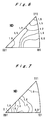
- Fig. 6 shows the orientation of ferrite grains and the density thereof in the steel sample obtained in Example 1.
- Fig. 7 shows the orientation of ferrite grains and the density thereof in the steel sample obtained in Example 2.
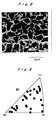
- Fig. 8 is a picture in scanning electromicroscopy (SEM), showing one embodiment of the structure of the steel of the invention.
- Fig. 9 shows the data in orientation analysis in Example 4.
- Fig. 10 is a graph showing the relationship between tensile strength and uniform elongation relative to the grain size of ferrite grains in a ferrite structure and in a ferrite-pearlite structure.
- Fig. 11 is a graph indicating the conventional knowledge of the relationship between the working ratio and the orientation density in a worked steel.
- the present invention provides novel, ultra-fine grain steel.
- the ultra-fine grain steel of the invention is characterized by the following requirements:
- the novel, ultra-fine grain steel is based on the findings of the inventors of the invention. After having variously studied in order to obtain ultra-fine ferrite grains as surrounded by large angle grain boundaries while their orientations are randomized, we, the inventors have found that the non-transformed austenite grain boundaries and also the annealing twin in the non-transformed austenite grains must be waved, or that is, they are not in straight lines. Specifically, we have found that the waved conditions are indispensable for forming ultra-fine ferrite grains as surrounded by large angle grain boundaries and also for randomizing the intragranular and intergranular ferrite grain orientations.
- Fig. 1 is a view graphically showing an austenite grain boundary in which ferrite grains are nucleated. As in Fig.
- ferrite nucleation occurs in the austenite grain boundary in such a manner that the ferrite grains grow in a relation of K-S relative to the austenite phase and that the closest packed plane of each grain meets the grain boundary plane at a smallest possible angle (f).
- the austenite grain boundaries are waved to thereby make the boundary planes faces in different directions, then the growing ferrite grains shall face in different directions, as in Fig. 2.
- the intergranular ferrite orientations are much randomized.
- the deformed zones and the annealing twin in austenite grain boundaries in worked steel could be nucleation sites comparable to the grain boundaries noted above. In this case, where they are in waves, like the grain boundaries in Fig. 2, the ferrite grains being formed could be oriented in different directions, like the intergranular ferrite grains noted above. Therefore, also in this case, the intragranular ferrite orientations are randomized.
- fine ferrite structure steel is realized in which the ferrite grains have a mean grain size of not larger than 3.0 microns and are surrounded by large angle grain boundaries in such a manner that the misorientation between the adjacent ferrite grains is not smaller than 15° and that the density of specific orientations of the ferrite grains is not larger than 4.
- austenite steel is processed.
- at least any of the following (A) and (B) are such that, when they are seen in the direction vertical to the grain boundaries, the linear grain boundary is waved at a cycle of not larger than 8 ⁇ m and at an amplitude of not smaller than 200 nm, in a ratio of not smaller than 70 % of the grain boundary unit length.
- the cycle and the amplitude for the waved structure are defined, for example, as in Fig. 3, in which the grain boundary (a) is waved at a cycle (L) of not larger than 8 ⁇ m (this means the length of one wave cycle) and at an amplitude (W) of not smaller than 200 nm (this means the width of one wave cycle).
- the requirements noted above can be attained by a process of austenitizing starting steel, followed by subjecting it to anvil compression working to a reduction ratio of not smaller than 30 %, at a non-recrystallized temperature not higher than the recrystallization point of austenite. After having been thus worked, the steel is then cooled at a rate not lower than 3 K/s. As a result of this working process, obtained is the intended ultra-fine grain steel of the invention.
- the cycle (L) and the amplitude (W) are defined to be at most 8 ⁇ m and at least 200 nm, respectively.
- the compression working is attained to a reduction ratio of not smaller than 30 %, but preferably not smaller than 50 %.
- One preferred embodiment of the compression working is anvil working, as in Fig. 4.
- the chemical composition of the ferrite structure steel of the invention is not specifically defined, and may comprise Si, Mn, C, P, S, N, Nb, Ti, V, Al and the like in any desired ratio.
- the C (carbon) content of the steel is not larger than 0.3 % by volume fraction.
- the present invention has realized the production of steels for construction that comprises ferrite grains having a mean grain size of not larger than 3.0 ⁇ m and having randomized orientations. Accordingly, the invention has brought about a novel route for producing high-strength steel.
- the invention obtained is ultra-fine grain steel without using any expensive elements such as Ni, Cr, Mo, Cu, etc.
- the invention has realized the production of high-strength steel at low production costs, and is therefore extremely meaningful in practical industries.
- the relationship between the width of the anvils to be used for working the steel plates in the invention and the thickness of the steel plate to be worked may be suitably controlled, and a lubricant may be applied between the anvil and the steel plate.
- starting steel is austenitized by heating it at a temperature not lower than its Ac 3 point, then worked for anvil compression to a reduction ratio of not smaller than 50 % at a temperature not higher than its Ar 3 point, and thereafter cooled at a rate not lower than 3 K/s.
- the grain size of the austenite grains constituting the starting, non-worked steel for use in the invention may well be 300 ⁇ m or smaller for forming the intended fine ferrite grains.
- the reduction ratio must be at least 50 %, but preferably at least 70 % for forming finer ferrite grains having a grain size of smaller than 2 microns.
- the working temperature must fall within the austenite non-recrystallized range, and is preferably below Ar 3 + 200°C. In order to obtain finer ferrite grains, it is desirable that the working temperature is below Ar 3 + 100°C.
- the mother phase of the steel of the invention is a ferrite one.
- the steel may have one or more of pearlite, martensite and remaining austenite phases, and may even contain precipitates of carbides, nitrides, oxides, etc.
- the second phase of the steel is a pearlite one
- its proportion is not larger than 40 % by volume fraction in order that the weldability and the toughness of the steel are prevented from being lowered.
- the mean grain size of the ferrite grains as referred to herein may be measured, for example, in a linear intercept method.
- the orientation of the ferrite grain boundaries may be measured as follows: Some typical visual fields having a size of about 0.1 x 0.1 mm in the worked part of a steel sample are observed in SEM, and hundreds of ferrite grains per one visual field are measured for their orientations through electron back scattering diffraction (EBSD) method. Ferrite grain boundaries in which the misorientation is not smaller than 15° are referred to as large angle grain boundaries. A structure in which the proportion of such large angle grain boundaries is not smaller than 80 % of all grain boundaries therein is referred to as a structure essentially comprising large angle grain boundaries.
- the steel of the invention may have any desired chemical composition with no specific limitation, and any expensive elements such as Ni, Cr, Mo, Cu and the like are not always needed in the composition.
- the composition of the steel may comprise Si, Mn, Al, P, S and N, along with C, and a balance of Fe and inevitable impurities.
- the steel of the invention may contain the following additive elements:
- C in an amount of 0.001 mass % ⁇ C ⁇ 0.3 mass %: C is an important element for increasing the strength of steel. However, if its content is larger than 0.3 %, the weldability and the toughness of the steel are lowered so that the steel could not be used in ordinary weld constructions.
- Si, Mn These are elements for reinforcing solid solutions in steel. It is desirable that a suitable amount of these is added to the steel. In view of the weldability of the steel, the Mn content may be at most 3 %, and the Si content may be at most 2.5 %.
- the Al content may be at most 0.1 %.
- P, S In general, these may be at most 0.05 % each.
- multi-axial working is preferred, as being able to effectively attain the same degree of fineness in a lower amount of working strain.
- obtained are finer grains in the same amount of working strain.
- the stress for the working may be induced by not only compression but also shearing, elongation or twisting.
- the both surfaces A and B of a steel sample is worked alternately. After this, the thus-worked sample is cooled at a suitable cooling rate. In that manner, the amount of ferrite grains formed to have different orientations is increased as compared with that in the case of mono-axial compression working. Accordingly, in the multi-axial compression working of that type, the grain size of the ferric grains formed may be smaller than that in the mono-axial compression working, when the two are effected to the same reduction ratio. Even if the reduction ratio in the multi-axial compression working is lower than that in the mono-axial compression working, finer ferrite grains can be formed in the multi-axial compression working.
- the present invention also provides a multi-axial hot-working technique for producing ultra-fine grain steel, in which starting steel is heated up to its Ac 3 point or higher to thereby austenitize it, and then cooled to a temperature falling within its non-recrystallized temperature range, while the working degree at each plane and the working temperature are suitably controlled, whereby the transformed ferrite grains are effectively made finer while being surrounded by large angle grain boundaries.
- the axis to be worked of the sample is one and the sample is worked at its two planes while it is rotated.
- two planes A and B of this sample may be worked alternately around two working axes previously prepared for them. When two working axes are prepared, the two planes A and B may be worked at the same time, and this mode is effective for further fining the ferrite grains formed.
- the strength of steel comprising ultra-fine ferrite grains having a grain size of not larger than 3 ⁇ m is much increased.
- the tensile strength of conventional ferrite steel that comprises ferrite grains having a grain size of 20 ⁇ m is only about 480 MPa or so.
- the ferrite steel of the invention having a mean grain size of 4 ⁇ m has a tensile strength of about 600 MPa, and that having a mean grain size of 2 ⁇ m has a tensile strength of about 700 MPa.
- the tensile strength of the steel of the invention is much higher than that of conventional steel.
- the ferrite grains constituting the steel of the invention are much fined, the ductility thereof is prevented from being lowered. Therefore, the steel of the invention has well balanced strength-ductility characteristics.
- the uniform elongation of the steel of the invention having a pearlite proportion of 25 % by volume fraction and having a mean ferrite grain size of 3 ⁇ m is increased to 125 %, and that of the steel having a mean ferrite grain size of 2 ⁇ m is increased to 200 %.
- the mean grain size of the ferrite grains constituting the steel of the invention is defined to be at most 3 ⁇ m.
- the practical effect of the invention is attained when the pearlite proportion is not smaller than 3 % by volume fraction.
- the uppermost limit of the pearlite proportion may be determined, depending on the acceptable range of the expected strength of the steel.
- referred to are the graphs of the tensile strength-uniform elongation balance of ferrite steel samples, as drawn relative to the variation in the grain size of ferrite grains, as in Fig. 10. The data plotted in Fig.
- Starting steel having Composition 1 in Table 1 was austenitized to have a controlled grain size of 15 microns, and subjected to one-pass anvil compression working to a reduction ratio of 73 % at 750°C and at a strain rate of 10/s.
- the steel was cooled with water immediately after the working, whereby it underwent martensite transformation to have a martensitic texture.
- the original austenite grain boundaries in this martensitic texture were observed, which were found to be in definite waves in a proportion of 85 % relative to the grain boundary unit length.
- the cycle of the waves was not larger than 5.5 microns, and the amplitude thereof was not smaller than 350 nm.
- the structure thus formed was a ferrite-pearlite one.
- the mean grain size of the ferrite grains as measured according to a linear intercept method was 2.0 microns.
- the information on the texture orientations in the plane (TD plane) vertical to the rolling direction was measured through three-dimensional crystallite orientation distribution function (ODF) by electron back scattering diffraction (EBSD) method.
- ODF crystallite orientation distribution function
- EBSD electron back scattering diffraction
- the proportion of the large angular grain boundaries in which the misorientation between the adjacent ferrite grains was not smaller than 15 degrees was 95 %, as calculated from of the ratio of the grain boundary lengths appeared in the measured plane.
- the percentage of the ferrite grains specifically defined in the invention was 75 % by volume fraction.
- Austenite having been prepared from steel of Composition 1 in Table 1 by austenitizing it to have an austenite grain size of 300 microns was subjected to one-pass anvil compression working to a reduction ratio of 73 % at 750°C and at a strain rate of 10/s.
- the steel was cooled with water immediately after the working, whereby it underwent martensite transformation to have a martensite structure.
- the original austenite grain boundaries in this martensite structure were observed, which were found to be in definite waves.
- the cycle of the waves was not larger than 6.1 microns, and the amplitude thereof was not smaller than 300 nm.
- the annealing twin bundaries therein were also observed, which were found to be in definite waves in a proportion of 80 % relative to the grain boundary unit length.
- the cycle of the waves was not larger than 6.2 microns, and the amplitude thereof was not smaller than 300 nm.
- the steel was further worked under the same condition as previously, whereby the austenite grain boundaries and the intragranular annealing twin boundaries were made to be in waves as above, and thereafter this was cooled at a rate of 10 K/s.
- the structure thus formed was a ferrite-pearlite one.
- the mean grain size of the grains as measured according to a linear intercept method was 2.6 microns.
- the information on the texture orientations in the plane (TD plane) vertical to the rolling direction was measured through ODF by EBSD above mentioned. As a result, it was found that orientations of ferite grains were randomly distributed and that the density of ⁇ 001 ⁇ //ND orientations was at most only 2.1, as illustrated in Fig. 7.
- the proportion of the large angle grain boundaries in which the misorientation between the adjacent ferrite grains was not smaller than 15 degrees was 94 %, as calculated from of the ratio of the grain boundary lengths appeared in the measured plane.
- the percentage of the ferrite grains specifically defined in the invention was 75 % by volume fraction.
- Austenite having been prepared from steel of Composition 1 in Table 1 by austenitizing it to have an austenite grain size of 15 microns was subjected to one-pass anvil compression working to a reduction ratio of 50 % at 750°C and at a strain rate of 10/s. Immediately after having been thus worked, the steel was cooled with water, and the original austenite structure still remaining therein was observed. Then, the thus-deformed steel was cooled at a cooling rate of 10 K/s, to thereby make it have a ferrite-pearlite structure. In the structure, the mean ferrite grain size of the grains as measured according to a linear intercept method was 2.4 microns.
- the information on the texture orientations was measured through ODF method according to EBSD above mentioned. As a result, it was found that the orientation density was 3.8.
- the proportion of the large angle grain boundaries in which the misorientation was not smaller than 15 degrees was 95 % relative to all ferrite grain boundaries in the structure, as calculated from of the ratio of the grain boundary lengths appeared in the measured plane.
- the original austenite grain boundaries were in waves in a proportion of 75 % relative to the grain boundary unit length.
- the cycle of the waves was not larger than 6.9 microns, and the amplitude thereof was not smaller than 300 nm.
- the orientations of the ferrite grains formed were measured according to EBSD above mentioned, and were found randomized.
- the percentage of the ferrite grains specifically defined in the invention was 75 % by volume fraction.
- Austenite having been prepared from steel of Composition 1 in Table 1 by austenitizing it to have an austenite grain size of 30 microns was directly cooled, without being further worked, whereby it underwent martensite transformation and had a martensite structure.
- the original austenite grains still existing in the martensite structure were observed, and it was found that the original austenite grain boundaries were in straight lines. No periodic waves were seen in the austenite grain boundaries, and the amplitude of the waves seen somewhere but not periodically therein was smaller than 200 nm. (mass %)
- Starting steel used herein had a composition of composition 1 in Table 2. This was melted in vacuum and hot-rolled. From the resulting materials, prepared were test pieces of 20 x 8 x 12 (mm) in size. These were subjected to anvil compression working, as showin in Fig. 4. Precisely, the test pieces were kept at a temperature falling between 850 and 1250°C for 60 to 600 seconds, then subjected to one-pass anvil compression to a reduction ratio falling between 50 and 85 %, at a temperature falling between 670 and 840°C and at a strain rate of 10/s, thereafter forcedly cooled at a cooling rate falling between 1 and 18 K/s, and then cooled with water.
- the structure in the center of the worked part and that of the non-worked part were observed with SEM, and the mean grain size of the grains existing therein was measured according to a linear intercept method.
- the orientations of the ferrite grains formed were measured by EBSD above mentioned
- Fig. 9 is a inverse pole figure, in which are plotted the compression axis-directed orientations of the ferrite grains. As in Fig. 9, no high density of specific orientations is seen, which indicates that the orientation distribution of the ferrite grains was randomized. Another region of 100 x 100 microns in size of the worked part, which is different from the region shown in Fig. 8, was analyzed for the grain boundary orientations therein by EBSD. As a result of the analysis, it was found that the proportion of the ferrite grain boundaries in which the misorientation between the adjacent ferrite grains was not smaller than 15° was 92 % of all the grain boundaries in the region.
- a steel sample having Composition 1 in Table 2 was hot-rolled, then cold-rolled and heated, whereby it had a ferrite-pearlite structure in which the ferrite grains had a mean grain size of 2.5 microns.
- EBSD analysis of the steel revealed that the proportion of the ferrite grain boundaries existing therein and having a misorientation of not smaller than 15° was 30 % of all the ferrite grain boundaries therein.
- the tensile strength of the steel was 480 N/mm 2 .
- Steel Sample No. C Si Mn P S N Al Ar 3 1 0.17 0.03 1.5 0.025 0.005 0.002 0.03 660 2 0.09 0.48 0.97 0.022 0.01 0.002 0.03 795 3 0.05 0.02 1.5 0.02 0.01 0.003 0.03 820
- a steel sample having Composition 1 in Table 2 was heated at 900°C, whereby it was completely austenitized. Next, this was cooled to 750°C, and subjected to anvil compression working at its plane A (see Fig. 5) to a reduction ratio of 15 %. After 0.1 seconds, it was subjected to anvil compression working at its plane B to a reduction ratio of 60 % of the original non-worked cross-section. Next, this was cooled to 500°C at a rate of 10 K/s. As a result of this working, the steel had a ferrite-pearlite structure, in which the mean grain size of the ferrite grains existing in the worked part was 2.0 microns. To all the ferrite grain boundaries in the worked part, the proportion of those having misorientation as measured by EBSD of not smaller than 15° was 94 %, and the ferrite grains were surrounded by the large angle grain boundaries.
- a steel sample having Composition 1 in Table 2 was heated at 900°C, whereby it was completely austenitized. Next, this was cooled to 750°C, and subjected to anvil compression working at its plane A (see Fig. 5) to a reduction ratio of 10 %. After 0.1 seconds, it was subjected to anvil compression working at its plane B to a reduction ratio of 45 % of the original non-worked cross-section. Next, this was cooled to 500°C at a rate of 10 K/s.
- the steel had a ferrite-pearlite structure, in which the mean grain size of the ferrite grains existing in the worked part was 2.5 microns. To all the ferrite grain boundaries in the worked part, the proportion of those having a misorientation measured by EBSD of not smaller than 15° was 95 %, and the ferrite grains were surrounded by the large angle grain boundaries.
- a steel sample having Composition 1 in Table 2 was heated at 900°C, whereby it was completely austenitized. Next, this was cooled to 750°C, and subjected to anvil compression working at its plane A (see Fig. 5) to a reduction ratio of 10 %. After 0.1 seconds, it was subjected to anvil compression working at its plane B to a reduction ratio of 70 % of the original non-worked cross-secton. Next, this was cooled to 500°C at a rate of 10 K/s. As a result of this working, the steel had a ferrite-pearlite structure, in which the mean grain size of the ferrite grains existing in the worked part was 1.4 microns. To all the ferrite grain boundaries in the worked part, the proportion of those having a misorientation as measured by EBSD of not smaller than 15° was 95 %, and the ferrite grains were surrounded by the large angle grain boundaries.
- a steel sample having Composition 1 in Table 4 was heated at 900°C, whereby it was completely austenitized. Next, this was cooled to 750°C, and immediately subjected to anvil compression working to a reduction ratio of 70 %, in the manner as illustrated in Fig. 4. After having been thus worked, this was cooled to 500°C at a rate of 10 K/s. As a result of this working, the steel had a ferrite-pearlite composite phase structure, in which the mean grain size of the ferrite grains existing in the worked part was 2.0 microns. The percentage of the pearlite in that area was 25 % by volume fraction.
- a steel sample having Composition 2 in Table 4 was heated at 950°C, whereby it was completely austenitized. Next, this was cooled to 800°C, and then worked in the same manner as in Example 20.
- the ferrite grains had a grain size of 3.0 microns, and the proportion of the pearlite structure was 10 % by volume fraction.
- the ferrite grains were surrounded by large angle grain boundaries. The tensile strength of the steel was 580 MPa and the uniform elongation thereof was 0.09.
- a steel sample having the same composition as in Example 20 was heated at 900°C, whereby it was completely austenitized. Next, this was cooled to 800°C, and rolled to a cumulative reduction ratio of 70 %. After having been rolled, the steel sheet was cooled to 500°C at a rate of 10 K/s. As a result of this working, the steel had a ferrite-pearlite structure, in which the ferrite grains in the worked part had a mean grain size of 6 microns.
- Ferrite steel having Composition 3 in Table 4 and having a mean grain size of 2 microns was produced according to powder metallurgy. Its tensile strength and uniform elongation (true strain) were 630 MPa and 0.03, respectively.
- the data indicate the unbalance of strength/ductility of the steel.
- a steel sample having Composition 1 in Table 4 was hot-rolled, then cold-rolled and heated, whereby it had a ferrite-pearlite structure in which the ferrite grains had a mean grain size of 3.2 microns.
- EBSD analysis of the steel revealed that the proportion of the ferrite grain boundaries existing therein and having a misorientation not smaller than 15° was 50 % of all the ferrite grain boundaries therein.
- the tensile strength and the uniform elongation of the steel were 530 MPa and 0.12, respectively.
- the present invention provides novel, high-strength, ultra-fine grain steel useful for general weld constructions, etc.
- the ultra-fine texture steel is ferrite structure steel, in which the ferrite structure have a mean grain size of not larger than 3 ⁇ m and are surrounded by large angle grain boundaries.
- the strength of the steel is much higher than that of conventional ultra-fine grain steel.
- the cooling rate may be slow.
- the novel method for producing the steel of the invention has the industrial advantage of slow cooling.
Landscapes
- Chemical & Material Sciences (AREA)
- Engineering & Computer Science (AREA)
- Crystallography & Structural Chemistry (AREA)
- Mechanical Engineering (AREA)
- Materials Engineering (AREA)
- Metallurgy (AREA)
- Organic Chemistry (AREA)
- Physics & Mathematics (AREA)
- Thermal Sciences (AREA)
- Heat Treatment Of Steel (AREA)
- Soft Magnetic Materials (AREA)
- Heat Treatment Of Sheet Steel (AREA)
Applications Claiming Priority (9)
| Application Number | Priority Date | Filing Date | Title |
|---|---|---|---|
| JP25680297A JPH1192855A (ja) | 1997-09-22 | 1997-09-22 | 超微細複相組織鋼 |
| JP25668297A JP3543104B2 (ja) | 1997-09-22 | 1997-09-22 | 超微細組織鋼とその製造方法 |
| JP25680297 | 1997-09-22 | ||
| JP256802/97 | 1997-09-22 | ||
| JP256682/97 | 1997-09-22 | ||
| JP25668297 | 1997-09-22 | ||
| JP5254598 | 1998-03-04 | ||
| JP5254598A JPH11246931A (ja) | 1998-03-04 | 1998-03-04 | 超微細フェライト組織鋼 |
| JP52545/98 | 1998-03-04 |
Publications (2)
| Publication Number | Publication Date |
|---|---|
| EP0903412A2 true EP0903412A2 (fr) | 1999-03-24 |
| EP0903412A3 EP0903412A3 (fr) | 2001-01-24 |
Family
ID=27294662
Family Applications (1)
| Application Number | Title | Priority Date | Filing Date |
|---|---|---|---|
| EP98307632A Ceased EP0903412A3 (fr) | 1997-09-22 | 1998-09-21 | Acier à grains ultra-fins et procédé de sa fabrication |
Country Status (5)
| Country | Link |
|---|---|
| US (1) | US6221178B1 (fr) |
| EP (1) | EP0903412A3 (fr) |
| KR (1) | KR100536827B1 (fr) |
| CN (1) | CN1121502C (fr) |
| TW (1) | TW580519B (fr) |
Cited By (5)
| Publication number | Priority date | Publication date | Assignee | Title |
|---|---|---|---|---|
| US6422090B1 (en) | 1999-04-07 | 2002-07-23 | Dynamic Systems Inc. | Apparatus for a thermodynamic material testing system that produces very large strains in crystalline metallic specimens and accompanying methods for use therein |
| EP1031632A3 (fr) * | 1999-02-26 | 2002-07-31 | Japan as represented by Director General of National Research Institute for Metals | Procédé de fabrication d'acier ayant une structure granulaire ultrafine |
| EP1176217A3 (fr) * | 2000-07-24 | 2003-04-23 | KABUSHIKI KAISHA KOBE SEIKO SHO also known as Kobe Steel Ltd. | Tôle d' acier à haute résistance laminé à chaud ayant une déformabilité de bordage par étirage excellente et son procédé de fabrication |
| US6719860B1 (en) | 1999-10-19 | 2004-04-13 | Aspector Oy | Method of producing ultra-fine grain structure for unalloyed or low-alloyed steel |
| EP1580291A4 (fr) * | 2002-10-17 | 2006-01-18 | Nat Inst For Materials Science | Acier a particules superfines dote d'une surface nitruree |
Families Citing this family (15)
| Publication number | Priority date | Publication date | Assignee | Title |
|---|---|---|---|---|
| DE69823126T2 (de) * | 1997-09-22 | 2004-08-26 | National Research Institute For Metals | Feinkorniger ferritischer Baustahl und Herstellungsverfahren dieses Stahles |
| US6878250B1 (en) * | 1999-12-16 | 2005-04-12 | Honeywell International Inc. | Sputtering targets formed from cast materials |
| US20040072009A1 (en) * | 1999-12-16 | 2004-04-15 | Segal Vladimir M. | Copper sputtering targets and methods of forming copper sputtering targets |
| US7517417B2 (en) * | 2000-02-02 | 2009-04-14 | Honeywell International Inc. | Tantalum PVD component producing methods |
| US6331233B1 (en) | 2000-02-02 | 2001-12-18 | Honeywell International Inc. | Tantalum sputtering target with fine grains and uniform texture and method of manufacture |
| ATE439197T1 (de) * | 2002-09-30 | 2009-08-15 | Rinascimetalli Ltd | Verfahren zur bearbeitung von metall |
| JP4284405B2 (ja) * | 2002-10-17 | 2009-06-24 | 独立行政法人物質・材料研究機構 | タッピングネジとその製造方法 |
| KR100946047B1 (ko) * | 2002-12-27 | 2010-03-09 | 주식회사 포스코 | 변형유기 동적변태를 이용한 고강도, 고인성 초세립강제조방법 |
| US20070084527A1 (en) * | 2005-10-19 | 2007-04-19 | Stephane Ferrasse | High-strength mechanical and structural components, and methods of making high-strength components |
| US20070251818A1 (en) * | 2006-05-01 | 2007-11-01 | Wuwen Yi | Copper physical vapor deposition targets and methods of making copper physical vapor deposition targets |
| KR100782748B1 (ko) | 2006-12-14 | 2007-12-05 | 주식회사 포스코 | 초미세 페라이트 조직을 갖는 강 및 그 제조 방법 |
| JP5464511B2 (ja) * | 2009-05-14 | 2014-04-09 | 独立行政法人物質・材料研究機構 | 液体噴射用オリフィスプレートの製造方法 |
| KR101294337B1 (ko) * | 2011-07-11 | 2013-08-08 | 호리코리아 주식회사 | 비계 버팀대 |
| KR101482359B1 (ko) | 2012-12-27 | 2015-01-13 | 주식회사 포스코 | 극저온 인성이 우수하고 저항복비 특성을 갖는 고강도 강판 및 그의 제조방법 |
| CN111944958B (zh) * | 2020-07-26 | 2022-09-20 | 杨军 | 一种高强度块体316l不锈钢的制备方法 |
Family Cites Families (6)
| Publication number | Priority date | Publication date | Assignee | Title |
|---|---|---|---|---|
| BE788922A (fr) * | 1971-09-21 | 1973-03-15 | Uss Eng & Consult | Procede pour produire une microstructure a grain ultrafin dans les alliages ferreux |
| JPS58221258A (ja) * | 1982-06-17 | 1983-12-22 | Nippon Steel Corp | 超細粒フエライト鋼とその製造方法 |
| US4466842A (en) * | 1982-04-03 | 1984-08-21 | Nippon Steel Corporation | Ferritic steel having ultra-fine grains and a method for producing the same |
| JPS59229413A (ja) * | 1983-06-10 | 1984-12-22 | Nippon Steel Corp | 超細粒フェライト鋼の製造方法 |
| US6027587A (en) * | 1993-06-29 | 2000-02-22 | The Broken Hill Proprietary Company Limited | Strain-induced transformation to ultrafine microstructure in steel |
| JPH10216884A (ja) * | 1997-01-31 | 1998-08-18 | Nippon Steel Corp | 金属材料の繰り返し横鍛造加工法および成形加工法 |
-
1998
- 1998-09-21 TW TW087115693A patent/TW580519B/zh not_active IP Right Cessation
- 1998-09-21 KR KR1019980038944A patent/KR100536827B1/ko not_active Expired - Lifetime
- 1998-09-21 EP EP98307632A patent/EP0903412A3/fr not_active Ceased
- 1998-09-21 US US09/157,394 patent/US6221178B1/en not_active Expired - Lifetime
- 1998-09-21 CN CN98120620A patent/CN1121502C/zh not_active Expired - Lifetime
Cited By (5)
| Publication number | Priority date | Publication date | Assignee | Title |
|---|---|---|---|---|
| EP1031632A3 (fr) * | 1999-02-26 | 2002-07-31 | Japan as represented by Director General of National Research Institute for Metals | Procédé de fabrication d'acier ayant une structure granulaire ultrafine |
| US6422090B1 (en) | 1999-04-07 | 2002-07-23 | Dynamic Systems Inc. | Apparatus for a thermodynamic material testing system that produces very large strains in crystalline metallic specimens and accompanying methods for use therein |
| US6719860B1 (en) | 1999-10-19 | 2004-04-13 | Aspector Oy | Method of producing ultra-fine grain structure for unalloyed or low-alloyed steel |
| EP1176217A3 (fr) * | 2000-07-24 | 2003-04-23 | KABUSHIKI KAISHA KOBE SEIKO SHO also known as Kobe Steel Ltd. | Tôle d' acier à haute résistance laminé à chaud ayant une déformabilité de bordage par étirage excellente et son procédé de fabrication |
| EP1580291A4 (fr) * | 2002-10-17 | 2006-01-18 | Nat Inst For Materials Science | Acier a particules superfines dote d'une surface nitruree |
Also Published As
| Publication number | Publication date |
|---|---|
| KR100536827B1 (ko) | 2006-02-28 |
| US6221178B1 (en) | 2001-04-24 |
| EP0903412A3 (fr) | 2001-01-24 |
| CN1121502C (zh) | 2003-09-17 |
| KR19990029986A (ko) | 1999-04-26 |
| CN1233665A (zh) | 1999-11-03 |
| TW580519B (en) | 2004-03-21 |
Similar Documents
| Publication | Publication Date | Title |
|---|---|---|
| US6221178B1 (en) | Ultra-fine grain steel and method for producing it | |
| CN101861406B (zh) | 高强度冷轧钢板 | |
| DE69800029T2 (de) | Hochfester, hochzäher Stahl und Verfahren zu dessen Herstellung | |
| EP2042616B1 (fr) | PLAQUE EN ACIER INOXYDABLE EN AUSTÉNITE ROULÉE AYANT UNE ÉPAISSEUR SUPÉRIEURE OU ÉGALE À 100 mm ET PROCÉDÉ DE PRODUCTION DE CELLE-CI | |
| EP4095280A1 (fr) | Tuyau en acier électrosoudé et son procédé de fabrication | |
| EP0796921B1 (fr) | Méthode de fabrication d'un produit épais en acier ayant une résistance mécanique et une ténacité élevées ainsi qu'une excellente soudabilité et une variation minimale des propriétés structurelles et physiques | |
| JP3375554B2 (ja) | 強度一延性バランスに優れた鋼管 | |
| JP2002285278A (ja) | 普通低炭素鋼を低ひずみ加工・焼鈍して得られる超微細結晶粒組織を有する高強度・高延性鋼板およびその製造方法 | |
| EP3521475A1 (fr) | Tuyau en acier soudé par résistance électrique destiné à une poutre de torsion | |
| US6375760B2 (en) | Method for controlling structure of two-phase steel | |
| US11739866B2 (en) | Electric resistance welded steel pipe for torsion beam | |
| JP2004211199A (ja) | 耐疲労特性に優れ、かつ強度−延性バランスに優れた高強度熱延鋼板およびその製造方法 | |
| KR102504963B1 (ko) | 높은 인장 강도의 강철 와이어 | |
| JPH1192858A (ja) | 繰返し大変形下での延性き裂進展抵抗の優れた鋼材及びその製造方法 | |
| CN114790530B (zh) | 一种高塑性超高强钢板及其制造方法 | |
| KR102437909B1 (ko) | 냉간 압조용 강재 및 그 제조 방법 | |
| US6348108B1 (en) | High toughness steel and a method for manufacturing the same | |
| Anshari et al. | Quantitative analysis of phase fraction and mechanical behaviour of friction stir processed carbon steels | |
| JPH0672258B2 (ja) | 均質性にすぐれた圧延棒鋼の製造方法 | |
| JP2808675B2 (ja) | 微細粒ベイナイト鋼材 | |
| Hao et al. | Mechanical properties and temper resistance of deformation induced ferrite in a low carbon steel | |
| JPH07150244A (ja) | 冷間加工用フェライトステンレス鋼の製造方法 | |
| JP5743382B2 (ja) | 耐震性構造物用鋼材及びその製造方法 | |
| JP3543104B2 (ja) | 超微細組織鋼とその製造方法 | |
| JPH0233768B2 (fr) |
Legal Events
| Date | Code | Title | Description |
|---|---|---|---|
| PUAI | Public reference made under article 153(3) epc to a published international application that has entered the european phase |
Free format text: ORIGINAL CODE: 0009012 |
|
| AK | Designated contracting states |
Kind code of ref document: A2 Designated state(s): DE FR GB SE |
|
| AX | Request for extension of the european patent |
Free format text: AL;LT;LV;MK;RO;SI |
|
| PUAL | Search report despatched |
Free format text: ORIGINAL CODE: 0009013 |
|
| AK | Designated contracting states |
Kind code of ref document: A3 Designated state(s): AT BE CH CY DE DK ES FI FR GB GR IE IT LI LU MC NL PT SE |
|
| AX | Request for extension of the european patent |
Free format text: AL;LT;LV;MK;RO;SI |
|
| 17P | Request for examination filed |
Effective date: 20010706 |
|
| AKX | Designation fees paid |
Free format text: DE FR GB SE |
|
| 17Q | First examination report despatched |
Effective date: 20020918 |
|
| APBN | Date of receipt of notice of appeal recorded |
Free format text: ORIGINAL CODE: EPIDOSNNOA2E |
|
| APBR | Date of receipt of statement of grounds of appeal recorded |
Free format text: ORIGINAL CODE: EPIDOSNNOA3E |
|
| APBK | Appeal reference recorded |
Free format text: ORIGINAL CODE: EPIDOSNREFNE |
|
| APAF | Appeal reference modified |
Free format text: ORIGINAL CODE: EPIDOSCREFNE |
|
| APBT | Appeal procedure closed |
Free format text: ORIGINAL CODE: EPIDOSNNOA9E |
|
| STAA | Information on the status of an ep patent application or granted ep patent |
Free format text: STATUS: THE APPLICATION HAS BEEN REFUSED |
|
| 18R | Application refused |
Effective date: 20070118 |