EP0902722B1 - Dispositif pour guider, commander, reguler, mesurer et controler des flux de liquides et installation de traitement des eaux - Google Patents
Dispositif pour guider, commander, reguler, mesurer et controler des flux de liquides et installation de traitement des eaux Download PDFInfo
- Publication number
- EP0902722B1 EP0902722B1 EP98904129A EP98904129A EP0902722B1 EP 0902722 B1 EP0902722 B1 EP 0902722B1 EP 98904129 A EP98904129 A EP 98904129A EP 98904129 A EP98904129 A EP 98904129A EP 0902722 B1 EP0902722 B1 EP 0902722B1
- Authority
- EP
- European Patent Office
- Prior art keywords
- outlet
- inlet
- channel
- membrane
- liquid
- Prior art date
- Legal status (The legal status is an assumption and is not a legal conclusion. Google has not performed a legal analysis and makes no representation as to the accuracy of the status listed.)
- Expired - Lifetime
Links
Images
Classifications
-
- B—PERFORMING OPERATIONS; TRANSPORTING
- B01—PHYSICAL OR CHEMICAL PROCESSES OR APPARATUS IN GENERAL
- B01D—SEPARATION
- B01D61/00—Processes of separation using semi-permeable membranes, e.g. dialysis, osmosis or ultrafiltration; Apparatus, accessories or auxiliary operations specially adapted therefor
- B01D61/02—Reverse osmosis; Hyperfiltration ; Nanofiltration
- B01D61/10—Accessories; Auxiliary operations
-
- C—CHEMISTRY; METALLURGY
- C02—TREATMENT OF WATER, WASTE WATER, SEWAGE, OR SLUDGE
- C02F—TREATMENT OF WATER, WASTE WATER, SEWAGE, OR SLUDGE
- C02F1/00—Treatment of water, waste water, or sewage
- C02F1/008—Control or steering systems not provided for elsewhere in subclass C02F
-
- Y—GENERAL TAGGING OF NEW TECHNOLOGICAL DEVELOPMENTS; GENERAL TAGGING OF CROSS-SECTIONAL TECHNOLOGIES SPANNING OVER SEVERAL SECTIONS OF THE IPC; TECHNICAL SUBJECTS COVERED BY FORMER USPC CROSS-REFERENCE ART COLLECTIONS [XRACs] AND DIGESTS
- Y10—TECHNICAL SUBJECTS COVERED BY FORMER USPC
- Y10T—TECHNICAL SUBJECTS COVERED BY FORMER US CLASSIFICATION
- Y10T137/00—Fluid handling
- Y10T137/8593—Systems
- Y10T137/87249—Multiple inlet with multiple outlet
-
- Y—GENERAL TAGGING OF NEW TECHNOLOGICAL DEVELOPMENTS; GENERAL TAGGING OF CROSS-SECTIONAL TECHNOLOGIES SPANNING OVER SEVERAL SECTIONS OF THE IPC; TECHNICAL SUBJECTS COVERED BY FORMER USPC CROSS-REFERENCE ART COLLECTIONS [XRACs] AND DIGESTS
- Y10—TECHNICAL SUBJECTS COVERED BY FORMER USPC
- Y10T—TECHNICAL SUBJECTS COVERED BY FORMER US CLASSIFICATION
- Y10T137/00—Fluid handling
- Y10T137/8593—Systems
- Y10T137/877—With flow control means for branched passages
- Y10T137/87885—Sectional block structure
Definitions
- the invention relates to a device for steering, control, Measurement and monitoring of liquid flows, especially for a membrane technical water treatment plant, and a water treatment plant.
- raw water becomes high pressure passed over a synthetic membrane.
- the one in the Ingredients present in water are removed from the membrane selectively retained, causing a separation into pure Water (permeate) and the retained ingredients containing water (concentrate).
- Membrane water treatment plants are known in which the fluid flows are directed through pipes be used for control, regulation and monitoring required functional elements, such as control valves, control valves, Pressure sensors, pressure switches, flow meters and similar in each case in the pipe system via screw connections are permanently installed.
- This conventional structure has the disadvantage that the Assembly time for the construction is disproportionately large and the overall structure takes up a lot of space. Further is the replacement of individual functional elements or the Inserting additional functional elements complicated and under Under certain circumstances only with a change in the entire structure to realize.
- EP-A-0 272 632 describes a device for controlling, regulating, Measurement and monitoring of liquid flows for one Water treatment plant according to the preamble of the claim 1 known.
- EP-A-0 347 297 is a control valve for a reverse osmosis water purification system known.
- the object of the invention is to provide a device for steering, Control and monitoring of liquid flows, in particular for a membrane technical water treatment plant, one use such a facility and a water treatment plant to provide which is space-saving and compact are a short assembly and repair time required and also with a wide range of applications are easy to use.
- the object is achieved by the device according to claim 1, the use according to claim 12 or by the Water treatment plant according to claim 13.
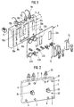
- the inventive Setting up a plate-shaped body 1 made of plastic or metal with a rectangular cross-section and a thickness d.
- the Base body 1 On one plate surface, which is defined as the front 2, the Base body 1 a plurality of groove-shaped elongated and each parallel to one of the outer edges of the base body 1 extending recesses or cutouts 10a, 10b, 10c ... on which individual channel sections of flow channels form for a liquid flowing in the base body 1.
- the recesses 10a, 10b, 10c, ... have a rectangular shape or circular cross-section.
- the basic body is made of gunmetal or glass fiber reinforced plastic, made of brass (MS), polypropylene random (PP-R) or VA educated. When using MS or gunmetal and highly concentrated The basic body is suitable for the medium refined or coated.
- the base body 1 also has in addition to the groove-shaped Recesses 10a, 10b ..., which the flow channels form, on its front 2 a number of others Recesses 12a, 12b, 12c with a rectangular cross section on, the edges of which are parallel to the outer edges of the base body 1 are aligned.
- the recesses 12a, 12b, 12c serve to accommodate appropriately dimensioned push elements or receiving bodies 13 for instruments.
- the base body instructs its rear surface 3 opposite the front side 2 a plurality of connections A, B, C, D, E, F, G, H on, through openings in defined positions in the back surface 3 are formed.
- the connections serve as liquid or transfers.
- connections 31, 32, 33, 34 at predetermined positions for measuring and Control devices provided.
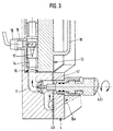
- a receiving body is in each case in the recesses 12a, 12b, 12c 13 with an outline corresponding to the recess for a functional element for steering, control, regulation or monitoring the liquid flow.
- the receiving body 13 a flow channel running vertically in the inserted position 14, which at its ends with predetermined Channel sections on the surface 2 of the base body 1 via flow channels provided in the interior of the base body 11 communicates.
- FIG. 3 shown receiving body 13 for connecting the in Fig. 1 shown recesses or channel sections 10e and 10d.
- the flow channel 14 of the receiving body 13 is at its connection point to the base body 1 via a Seal in the form of a rubber ring 15 against leakage Liquid sealed to the environment.
- the receiving body 13 has in its inserted position the front facing rear surface a tubular extension 16 on the through on the back surface 3 of the base body 1 provided opening extends through and over the opening in the rear surface 3 with the flow channel 14 in connection stands.
- the receiving body 13 has a turbine 17 in it
- Flow channel 14 is on and at the rear approach a sensor 18 is provided.
- the Receiving body on its opposite the approach 16 Side a handle 19 with which it is in the recess inserted and pulled out again can.
- the recesses 10a, 10b, 10c, ... are on the front of the base body via the receiving body 13, the flow channels 11 provided inside the base body and the connections provided on the back to one defined channel system connected.
- a front plate 4 is provided, which the same Outline of how the base body 1 has and that on the base body detachable but non-rotatable relative to this, for example fixed by screws.
- the front plate 4 covers the recesses 10a, 10b, 10c ... being between the front panel 4 and the edge the recesses 10a, 10b, 10c ... each have a seal 40 to prevent liquid from escaping from the channel sections 10a, 10b, 10c, ... is provided.
- the seal is designed for example in the form of rubber sealing rings.
- the front plate 4 also has a plurality of openings 41 at predetermined positions, in which functional elements 42a, 42b, 42c, ... for steering, control, regulation and monitoring of through the flow channels of the base body flowing water, such as control valves, Control valves, check valves, pressure gauges, pressure switches, Flow meters and conductivity meters as well Sample taps are attached.
- functional elements 42a, 42b, 42c, ... for steering, control, regulation and monitoring of through the flow channels of the base body flowing water, such as control valves, Control valves, check valves, pressure gauges, pressure switches, Flow meters and conductivity meters as well Sample taps are attached.
- Fig. 1 represents the functional element with the reference numeral 42a a manometer
- Functional element with the reference numeral 42b a sample tap
- the functional element with the reference symbol 42c is a valve represents.
- the front plate 4 has a plurality of openings 43a, 43b, 43c corresponding to the recesses 12a, 12b, 12c of the base body 1 through which the receiving body 13 even with the front panel 4 attached by pulling it out and Insert can be replaced.
- the base body 1 has between the Front 2 and rear 3 lying top 5 further openings, which with the channel system in the base body are connected and in the conductivity sensors, for example 51 are used or the one Have actuator 52, which the receiving body 13th fixed.
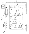
- a membrane technical water treatment plant according to the invention 100 is shown in FIG. 4.
- the water treatment plant has a device 101 for steering, Control, regulation and monitoring of liquid flows on, which will be referred to as control block 101.
- the water treatment system also has a membrane 102 with an input M1 and two outputs M2 and M3 for the Liquid on.
- To achieve one for the overflow the membrane 102 necessary fluid pressure is one High pressure pump 103 with an input P1 and an output P2 provided.
- Required electrical facilities for the system is provided in a separate electrical cabinet 104.
- To pre-filter the incoming raw water is a Fine filter 105 provided.
- the control block 101 has four inputs C, A, E and G as well four outputs D, B, F, H on.
- the entrance A stands with the Output B via one provided in the control block 101
- Flow channel K1 in connection the flow channel one after the other between input A and output B has the following instruments or elements: a sample tap 3A, a solenoid valve 2A, a pressure switch 5A Pressure gauge 4A and a conductivity probe 8A.
- the exit B is connected to the input P1 of the pump 103 and the output P2 of the pump 103 is connected to the input C.
- the input C in the control block 101 is over a flow channel K2 connected to the outlet D.
- Flow channels K2 are consecutive between the entrance C and the output D arranged the following instruments: a pressure switch 5C, a pressure manometer 4C, a setting valve 1C and another pressure manometer 4C '.
- the output D is connected to the input M1 of the membrane 102.
- the permeate discharge outlet M3 of the membrane 102 is connected to input G of control block 101.
- the input G is provided in the control block 101
- Flow channel K3 connected to the output H.
- In the channel K3 are successive between G and H following Instruments arranged: a sample tap 3G, a flow meter 7G, a check valve 6G and a conductivity probe 8G.
- Channel K3 is used for monitoring and derivation of the permeate emerging from the outlet M3 of the membrane as a cleaned product.
- the outlet M2 of the membrane 102 that discharges the concentrate is connected to input E of the control block.
- the entrance E of the control block is over one in the control block 101 provided flow channel K4 connected to the output B.
- the following are between input E and output B Instruments arranged one after the other: a setting valve 1E, a flow meter 7E and a check valve 6E.
- Channel K4 is used to return a part of the concentrate leaving the exit M2 of the membrane via the pump 103 into the membrane 102.
- the input E of the control block 101 is with the output F via a channel K5 provided in the control block connected.
- a channel K5 provided in the control block connected.
- the following instruments are provided in succession: a Sample valve 3F, a pressure manometer 4F, a setting valve 1F, a flow meter 7F, a check valve 6F and one Conductivity probe 8F.
- Channel K5 is used for drainage of a part of the membrane leaving the exit M2 Concentrate as residual water.
- the input E is via another, in the control block 101 formed channel K6 connected to the output F, a solenoid valve 2F being provided in the channel K6 is.
- Channel K6 is required if the membrane ends after production or flushed with raw water after a fault becomes.
- the control block 101 is like that in FIGS. 1 to 3 shown embodiment formed. That means, that all channels on the surface or within the body run.
- the connections of the control block are provided on the back of the body, while the Control, regulation and monitoring elements on the front are provided and thus clear and easily accessible are arranged for an operator.
- the operation the membrane water treatment plant will be in following described with reference to FIG. 4.
- the filtered through fine filter 105 flows Raw water above that on the back of control block 101 provided connection A in the main body of the control block and passes the instruments provided in channel K1, namely the sample tap 3A, the solenoid valve 2A, the Pressure gauge 4A and the pressure switch 5A.
- the raw water leaves the control block at exit B as mixed water in Direction of high pressure pump 103, the necessary operating pressure builds up.
- This mixed water occurs at port C on the back the control block back into the base body.
- Supervised and preset by pressure switch 5C, the pressure gauge 4C, the adjusting valve 1C, the other pressure gauge 4C 'and the conductivity probe 8A come under pressure set mixed water via outlet D on the back the control block into the membrane 102.
- the membrane separates the mixed water in two different qualities and quantities. A part flows as a product through the outlet M3 the membrane in the provided on the back of the control block Port G in the base body is over the Sample tap 3G, the flow meter 7G, the check valve 6G and the conductivity probe 8G checked and leaves the base at output H on the rear of the control block for further use.
- the second, leaving the membrane at the exit M2 as a concentrate Part flows into the base body at connection E. and is again divided into two different streams.
- the main flow is via channel K4, via the adjusting valve 1E, the flow meter 7E and the reset valve 6E the raw water to secure the discharge on the Membrane 102 supplied.
- This repatriation of part of the Concentrate is needed to keep the flow rate up keep the membrane constant so the membrane does not Filter effect shows. The yield can thus be increased to around 75% increase.
- the smaller part of the concentrate is channel K5 via the sample tap 3F, the pressure gauge 4F, the adjusting valve 1F, the flow meter 7F, the check valve 6F and the conductivity probe 8F via the output F on the Drained back of the control block to not the system to block. This residual water is fed into the sewer.
- the membrane 102 via the connection E, the output F and the channel K6 with the Solenoid valve 2F rinsed free with raw water.
- control device or the control block also for other membrane technical water treatment plants can be used, for example for nanofiltration systems, Ultrafiltration systems and microfiltration systems.
- the described is particularly suitable Control system for medium-sized plants with approx. 600 to 2000 l / h Product quantity but also for small plants with approx. 50 to 500 l / h product quantity.
Landscapes
- Water Supply & Treatment (AREA)
- Chemical & Material Sciences (AREA)
- Engineering & Computer Science (AREA)
- Organic Chemistry (AREA)
- Environmental & Geological Engineering (AREA)
- Hydrology & Water Resources (AREA)
- Life Sciences & Earth Sciences (AREA)
- Nanotechnology (AREA)
- Chemical Kinetics & Catalysis (AREA)
- Separation Using Semi-Permeable Membranes (AREA)
- Steering Control In Accordance With Driving Conditions (AREA)
- Control Of Non-Electrical Variables (AREA)
- Flow Control (AREA)
Claims (13)
- Dispositif pour guider, réguler, mesurer et contrôler des flux de liquides pour une installation de traitement des eauxcomportant un bloc (1, 4) dans lequel sont prévues des sections de canaux pour un flux de liquide formant des évidements (10a, 10b, 10c,...)et comportant une entrée et une sortie (A, B, C, D, E, F, G, H) pour le liquide, communiquant avec les sections de canaux, de façon qu'au moins un élément fonctionnel (42a, 42b, 42c, 18, 19) puisse être prévu pour guider, commander, réguler ou contrôler le liquide circulant dans les sections de canaux,caractérisé en ce que le bloc (1, 4) comporte un premier corps en forme de plaque (1) ayant une surface (2) etun second corps en forme de plaque (4) relié en rotation au premier corps et obturant les évidements (10a, 10b, 10c,...) de façon étanche par rapport au milieu ambiant (4), de façon que les évidements (10a, 10b, 10c,...) soient prévus à la surface (2) du premier corps en forme de plaque (1).
- Dispositif selon la revendication 1, caractérisé en ce que le premier corps présente en outre des espaces creux sous la forme de canaux (11) s'étendant à l'intérieur.
- Dispositif selon la revendication 2, caractérisé en ce que le premier corps (1) présente, sur une face opposée à sa surface, des orifices (A, B, C, D, E, F, G, H) pour l'entrée et la sortie, lesquels communiquent avec les évidements (10a, 10b, 10c, 10d,...).
- Dispositif selon la revendication 3, caractérisé en ce que les évidements (10a, 10b, 10c, ...) à la surface, les canaux d'écoulement (11) à l'intérieur et les orifices (A, B, C, ...) constituent le système de canaux pour le liquide.
- Dispositif selon l'une quelconque des revendications 1 à 4, caractérisé en ce que le second corps (4) présente au moins un orifice communiquant avec l'un des évidements (10a, 10b, 10c, ...) à la surface du premier corps et dans lequel est disposé un premier élément fonctionnel (42a, 42b, 42c) pour commander, réguler ou contrôler un flux de liquide.
- Dispositif selon l'une quelconque des revendications 1 à 5, caractérisé en ce que le premier corps est réalisé en une pièce moulée.
- Dispositif selon l'une quelconque des revendications 1 à 6, caractérisé en ce que le premier corps présente sur sa surface au moins un autre évidement (12a, 12b, 12c) dans lequel peut être inséré un corps récepteur (13) contenant un second élément fonctionnel pour commander, réguler ou contrôler le flux de liquide.
- Dispositif selon la revendication 7, caractérisé en ce que le corps récepteur (13) peut être introduit ou retiré dans l'évidement, à travers un orifice (43a, 43b, 43c) pratiqué dans le second corps (4) et ayant une section correspondant à celle de l'évidement (12a, 12b, 12c).
- Dispositif selon l'une des revendications 7 ou 8, caractérisé en ce que la zone de liaison entre le corps récepteur et le premier corps (1) est rendue étanche, afin d'empêcher toute fuite de liquide.
- Dispositif selon l'une quelconque des revendications 1 à 9, caractérisé en ce que le premier corps (1) présente la forme d'une plaque ayant une épaisseur définie (d) et que le second corps (4) présente également la forme d'une plaque dont l'épaisseur est inférieure à l'épaisseur du premier corps.
- Dispositif selon l'une quelconque des revendications 5 à 10, caractérisé en ce que les éléments fonctionnels comportent des vannes de réglage, des manomètres, des interrupteurs à poussoir, des débitmètres, des vannes de commande, des clapets de retenue et des sondes de conductibilité.
- Utilisation d'un dispositif selon l'une quelconque des revendications 1 à 10 en tant que bloc de commande dans une installation de traitement des eaux par procédé à membrane.
- Installation de traitement des eaux comportantune membrane (102) ayant une entrée (M1), une première sortie (M2) et une seconde sortie (M3),une pompe (103) etun dispositif de commande (101) qui comporteune première entrée (A) une seconde entrée (C), une troisième entrée (G) et une quatrième entrée (E) etune première sortie (B), une seconde sortie (D), une troisième sortie (H) et une quatrième sortie (F),la première entrée (A) communiquant par un premier canal (K1) avec la première sortie (B),la seconde entrée (C) communiquant par un second canal (K2) avec la seconde sortie (D),la troisième entrée (G) communiquant par un troisième canal (K3) avec la troisième sortie(H) etla quatrième entrée (E) communiquant par un quatrième canal (K4) avec la première sortie (B),ainsi que par un cinquième canal (K5) avec la quatrième sortie (F),la première sortie (D) communiquant via la pompe (103) avec la seconde entrée (C), la seconde sortie (D) communiquant avec l'entrée (M1) la membrane (102), et la première sortie (M2) de la membrane communiquant avec la quatrième entrée (E) et la seconde sortie (M3) de la membrane communiquant avec la troisième entrée (G),le dispositif de commande (101) étant constitué sous forme de bloc et en ce bloc qu'il est prévu au moins un élément fonctionnel (42a, 42b, 42c, 18, 19) pour guider, commander, réguler ou contrôler le flux de liquide circulant dans les canaux, ledit bloc étant constitué d'un corps de base comportant les canaux et d'une plaque recouvrant lesdits canaux.
Applications Claiming Priority (3)
| Application Number | Priority Date | Filing Date | Title |
|---|---|---|---|
| DE19704656 | 1997-02-07 | ||
| DE19704656A DE19704656A1 (de) | 1997-02-07 | 1997-02-07 | Einrichtung zur Lenkung, Steuerung, Regelung, Messung und Überwachung von Flüssigkeitsströmen und Wasseraufbereitungsanlage |
| PCT/EP1998/000372 WO1998034717A1 (fr) | 1997-02-07 | 1998-01-23 | Dispositif pour guider, commander, reguler, mesurer et controler des flux de liquides et installation de traitement des eaux |
Publications (2)
| Publication Number | Publication Date |
|---|---|
| EP0902722A1 EP0902722A1 (fr) | 1999-03-24 |
| EP0902722B1 true EP0902722B1 (fr) | 2001-08-16 |
Family
ID=7819598
Family Applications (1)
| Application Number | Title | Priority Date | Filing Date |
|---|---|---|---|
| EP98904129A Expired - Lifetime EP0902722B1 (fr) | 1997-02-07 | 1998-01-23 | Dispositif pour guider, commander, reguler, mesurer et controler des flux de liquides et installation de traitement des eaux |
Country Status (8)
| Country | Link |
|---|---|
| US (1) | US6136196A (fr) |
| EP (1) | EP0902722B1 (fr) |
| JP (1) | JP2000508586A (fr) |
| AT (1) | ATE204203T1 (fr) |
| DE (2) | DE19704656A1 (fr) |
| DK (1) | DK0902722T3 (fr) |
| ES (1) | ES2163252T3 (fr) |
| WO (1) | WO1998034717A1 (fr) |
Families Citing this family (8)
| Publication number | Priority date | Publication date | Assignee | Title |
|---|---|---|---|---|
| NL1012311C2 (nl) * | 1999-06-11 | 2000-12-12 | Pantser Stichting | Klephuis voor osmoseinrichting. |
| US6699684B2 (en) * | 2002-07-23 | 2004-03-02 | Nalco Company | Method of monitoring biofouling in membrane separation systems |
| US20050045532A1 (en) * | 2003-09-02 | 2005-03-03 | Kuo-Chi Yen | Deionized water filtration unit |
| EP1834927B8 (fr) * | 2006-03-17 | 2019-06-26 | Aquis Wasser-Luft-Systeme GmbH, Lindau, Zweigniederlassung Rebstein | Appareil de traitement de l'eau comprenant un dispositif mélangeur |
| US8343338B2 (en) * | 2008-10-09 | 2013-01-01 | Watts Water Technologies, Inc. | Reverse osmosis water filtering system |
| USD754613S1 (en) * | 2014-07-24 | 2016-04-26 | Aquion, Inc. | Controller |
| US10780377B2 (en) | 2016-11-30 | 2020-09-22 | Watts Regulator Co. | Sanitizing filter system and method for a residential water filtering system |
| AU2018336080B2 (en) * | 2017-09-25 | 2023-11-02 | Meunier Technologies Inc. | Apparatus and method for dosage and administration of liquid chemicals |
Family Cites Families (11)
| Publication number | Priority date | Publication date | Assignee | Title |
|---|---|---|---|---|
| DE1062506B (de) * | 1956-04-09 | 1959-07-30 | William Carls | Anschlusssockel fuer eine Vielzahl von Steuerventilen fuer druckmittelbetaetigte Arbeitszylinder |
| DE2119224B2 (de) * | 1971-04-21 | 1977-09-29 | Robert Bosch Gmbh, 7000 Stuttgart | Baueinheit zum aufbau einer mit druckmittel fuehrenden kanaelen versehenen grundplatte |
| US4741823A (en) * | 1986-12-23 | 1988-05-03 | Osmonics, Inc. | Flow control manifold for cross-flow membrane system |
| US4770209A (en) * | 1987-07-23 | 1988-09-13 | Mac Valves, Inc. | Valve base with integral flow controls |
| US4876002A (en) * | 1988-06-13 | 1989-10-24 | Schlumberger Industries, Inc. | Reverse osmosis water purificaiton unit |
| US5045197A (en) * | 1990-08-03 | 1991-09-03 | Burrows Bruce D | Reverse osmosis purification system with unitary header manifold |
| US5122265A (en) * | 1991-07-10 | 1992-06-16 | Hoh Water Technology Corp. | Compact reverse osmosis system with cold water flush |
| US5290442A (en) * | 1991-09-24 | 1994-03-01 | Clack Corporation | Self-contained, purified drinking water refrigerator storage apparatus |
| DE4412247A1 (de) * | 1994-04-06 | 1995-10-12 | Mannesmann Ag | Wegeventil in Grundplattenausführung |
| US5662793A (en) * | 1996-01-05 | 1997-09-02 | Beall, Jr.; Richard W. | Valve assembly of a reverse osmosis water purification system |
| US5660720A (en) * | 1996-01-31 | 1997-08-26 | Walling; David F. | Connector system for use with reverse osmosis water purifier |
-
1997
- 1997-02-07 DE DE19704656A patent/DE19704656A1/de not_active Ceased
-
1998
- 1998-01-23 US US09/155,886 patent/US6136196A/en not_active Expired - Fee Related
- 1998-01-23 WO PCT/EP1998/000372 patent/WO1998034717A1/fr not_active Ceased
- 1998-01-23 EP EP98904129A patent/EP0902722B1/fr not_active Expired - Lifetime
- 1998-01-23 DK DK98904129T patent/DK0902722T3/da active
- 1998-01-23 ES ES98904129T patent/ES2163252T3/es not_active Expired - Lifetime
- 1998-01-23 AT AT98904129T patent/ATE204203T1/de not_active IP Right Cessation
- 1998-01-23 DE DE59801210T patent/DE59801210D1/de not_active Expired - Lifetime
- 1998-01-23 JP JP10533694A patent/JP2000508586A/ja active Pending
Also Published As
| Publication number | Publication date |
|---|---|
| DK0902722T3 (da) | 2001-11-05 |
| WO1998034717A1 (fr) | 1998-08-13 |
| DE59801210D1 (de) | 2001-09-20 |
| US6136196A (en) | 2000-10-24 |
| EP0902722A1 (fr) | 1999-03-24 |
| ATE204203T1 (de) | 2001-09-15 |
| JP2000508586A (ja) | 2000-07-11 |
| ES2163252T3 (es) | 2002-01-16 |
| DE19704656A1 (de) | 1998-08-13 |
Similar Documents
| Publication | Publication Date | Title |
|---|---|---|
| EP0947237B1 (fr) | Dispositif de séparation de milieux liquides chargés d'impuretés | |
| DE3782926T2 (de) | Durchflussregelungsverteiler fuer membrananlage mit querstroemung. | |
| EP2158958B1 (fr) | Dispositif et procédé destiné au lavage à contre courant de modules membranaires | |
| DE2313983C2 (de) | Einrichtung zur Steuerung und/oder Konditionierung eines Fluids mit mindestens einer Steuer- oder Konditioniervorrichtung | |
| EP2190561A2 (fr) | Module de filtre et empilement de ces modules en un système de filtre | |
| DE102008001635A1 (de) | Verschneideventil und Vorrichtung zur Behandlung von Flüssigkeiten | |
| EP0902722B1 (fr) | Dispositif pour guider, commander, reguler, mesurer et controler des flux de liquides et installation de traitement des eaux | |
| EP1608902B1 (fr) | Dispositif pour reguler l'ecoulement de milieux liquides ou gazeux | |
| EP1046419A1 (fr) | Dispositif pour l'élimination physique des germes, particules en suspension et solides de l'eau | |
| EP1497591A1 (fr) | Soupape de distributeur comprenant un debitmetre a integrer dans l'alimentation | |
| EP2180226A1 (fr) | Système de distribution de fluide modulaire | |
| DE10302580B4 (de) | Wasser-Reinigungsvorrichtung | |
| DE102009031044B4 (de) | Anschluss einer sekundären Leitung einer Reinwasser-Hauptversorgungsleitung an ein Dialysegerät oder dergleichen | |
| DE4015336A1 (de) | Vorrichtung zum reinigen von wasser nach dem umkehrosmose-verfahren | |
| DE102020107587A1 (de) | Verfahren zum Reinigen einer Flüssigkeit sowie Ultrafiltrationsvorrichtung | |
| DE3807258A1 (de) | Verfahren und vorrichtung zum filtrieren von fluessigen medien | |
| DE29723865U1 (de) | Einrichtung zur Lenkung, Steuerung, Regelung, Messung und Überwachung von Flüssigkeitsströmen für eine Wasseraufbereitungsanlage und Wasseraufbereitungsanlage | |
| EP0862022A2 (fr) | Installation de traitement d'eau comprenant un filtre | |
| EP3828142A1 (fr) | Système de conduite destiné au pré-traitement de l'eau potable et procédé de fonctionnement du système de conduite | |
| DE102018004890A1 (de) | Filtersystem für biopharmazeutische Prozesse | |
| DE3710968A1 (de) | Vorrichtung zur messung des volumen- oder massenstromes | |
| EP2241864A2 (fr) | Dispositif de mesure du débit d'un fluid avec un dispositif de liaison pour le capteur | |
| EP3170517A1 (fr) | Dispositif de détection et système comprenant un dispositif de détection | |
| DE19716752C1 (de) | Vorrichtung zum Filtern und Trennen von flüssigen und gasförmigen Medien und/oder zum Trocknen gasförmiger Medien | |
| EP2540674A1 (fr) | Procédé et dispositif de protection du côté perméat de filtres à membrane contre une regermination |
Legal Events
| Date | Code | Title | Description |
|---|---|---|---|
| PUAI | Public reference made under article 153(3) epc to a published international application that has entered the european phase |
Free format text: ORIGINAL CODE: 0009012 |
|
| 17P | Request for examination filed |
Effective date: 19980819 |
|
| AK | Designated contracting states |
Kind code of ref document: A1 Designated state(s): AT DE DK ES FR GB IT NL |
|
| 17Q | First examination report despatched |
Effective date: 19990702 |
|
| GRAG | Despatch of communication of intention to grant |
Free format text: ORIGINAL CODE: EPIDOS AGRA |
|
| RBV | Designated contracting states (corrected) |
Designated state(s): AT DE DK ES FR GB IT NL |
|
| GRAG | Despatch of communication of intention to grant |
Free format text: ORIGINAL CODE: EPIDOS AGRA |
|
| GRAH | Despatch of communication of intention to grant a patent |
Free format text: ORIGINAL CODE: EPIDOS IGRA |
|
| GRAH | Despatch of communication of intention to grant a patent |
Free format text: ORIGINAL CODE: EPIDOS IGRA |
|
| GRAA | (expected) grant |
Free format text: ORIGINAL CODE: 0009210 |
|
| AK | Designated contracting states |
Kind code of ref document: B1 Designated state(s): AT DE DK ES FR GB IT NL |
|
| REF | Corresponds to: |
Ref document number: 204203 Country of ref document: AT Date of ref document: 20010915 Kind code of ref document: T |
|
| GBT | Gb: translation of ep patent filed (gb section 77(6)(a)/1977) |
Effective date: 20010816 |
|
| REF | Corresponds to: |
Ref document number: 59801210 Country of ref document: DE Date of ref document: 20010920 |
|
| REG | Reference to a national code |
Ref country code: DK Ref legal event code: T3 |
|
| ET | Fr: translation filed | ||
| REG | Reference to a national code |
Ref country code: GB Ref legal event code: IF02 |
|
| REG | Reference to a national code |
Ref country code: ES Ref legal event code: FG2A Ref document number: 2163252 Country of ref document: ES Kind code of ref document: T3 |
|
| PLBE | No opposition filed within time limit |
Free format text: ORIGINAL CODE: 0009261 |
|
| STAA | Information on the status of an ep patent application or granted ep patent |
Free format text: STATUS: NO OPPOSITION FILED WITHIN TIME LIMIT |
|
| 26N | No opposition filed | ||
| PGFP | Annual fee paid to national office [announced via postgrant information from national office to epo] |
Ref country code: GB Payment date: 20050112 Year of fee payment: 8 |
|
| PGFP | Annual fee paid to national office [announced via postgrant information from national office to epo] |
Ref country code: NL Payment date: 20050118 Year of fee payment: 8 |
|
| PGFP | Annual fee paid to national office [announced via postgrant information from national office to epo] |
Ref country code: DK Payment date: 20050121 Year of fee payment: 8 |
|
| PGFP | Annual fee paid to national office [announced via postgrant information from national office to epo] |
Ref country code: ES Payment date: 20050124 Year of fee payment: 8 |
|
| PG25 | Lapsed in a contracting state [announced via postgrant information from national office to epo] |
Ref country code: GB Free format text: LAPSE BECAUSE OF NON-PAYMENT OF DUE FEES Effective date: 20060123 |
|
| PG25 | Lapsed in a contracting state [announced via postgrant information from national office to epo] |
Ref country code: ES Free format text: LAPSE BECAUSE OF NON-PAYMENT OF DUE FEES Effective date: 20060124 |
|
| PG25 | Lapsed in a contracting state [announced via postgrant information from national office to epo] |
Ref country code: DK Free format text: LAPSE BECAUSE OF NON-PAYMENT OF DUE FEES Effective date: 20060131 |
|
| PG25 | Lapsed in a contracting state [announced via postgrant information from national office to epo] |
Ref country code: NL Free format text: LAPSE BECAUSE OF NON-PAYMENT OF DUE FEES Effective date: 20060801 |
|
| REG | Reference to a national code |
Ref country code: DK Ref legal event code: EBP |
|
| GBPC | Gb: european patent ceased through non-payment of renewal fee |
Effective date: 20060123 |
|
| NLV4 | Nl: lapsed or anulled due to non-payment of the annual fee |
Effective date: 20060801 |
|
| REG | Reference to a national code |
Ref country code: ES Ref legal event code: FD2A Effective date: 20060124 |
|
| PGFP | Annual fee paid to national office [announced via postgrant information from national office to epo] |
Ref country code: IT Payment date: 20070504 Year of fee payment: 10 |
|
| PGFP | Annual fee paid to national office [announced via postgrant information from national office to epo] |
Ref country code: FR Payment date: 20070118 Year of fee payment: 10 |
|
| REG | Reference to a national code |
Ref country code: FR Ref legal event code: ST Effective date: 20081029 |
|
| PG25 | Lapsed in a contracting state [announced via postgrant information from national office to epo] |
Ref country code: FR Free format text: LAPSE BECAUSE OF NON-PAYMENT OF DUE FEES Effective date: 20080131 |
|
| PGFP | Annual fee paid to national office [announced via postgrant information from national office to epo] |
Ref country code: AT Payment date: 20090122 Year of fee payment: 12 |
|
| PG25 | Lapsed in a contracting state [announced via postgrant information from national office to epo] |
Ref country code: IT Free format text: LAPSE BECAUSE OF NON-PAYMENT OF DUE FEES Effective date: 20080123 |
|
| PG25 | Lapsed in a contracting state [announced via postgrant information from national office to epo] |
Ref country code: AT Free format text: LAPSE BECAUSE OF NON-PAYMENT OF DUE FEES Effective date: 20100123 |
|
| PGFP | Annual fee paid to national office [announced via postgrant information from national office to epo] |
Ref country code: DE Payment date: 20140130 Year of fee payment: 17 |
|
| REG | Reference to a national code |
Ref country code: DE Ref legal event code: R082 Ref document number: 59801210 Country of ref document: DE Representative=s name: PATENTANWAELTE CHARRIER RAPP & LIEBAU, DE |
|
| REG | Reference to a national code |
Ref country code: DE Ref legal event code: R119 Ref document number: 59801210 Country of ref document: DE |
|
| PG25 | Lapsed in a contracting state [announced via postgrant information from national office to epo] |
Ref country code: DE Free format text: LAPSE BECAUSE OF NON-PAYMENT OF DUE FEES Effective date: 20150801 |