EP0902722B1 - Device for controlling, guiding, adjusting, measuring and monitoring liquid flows, and water treatment facility - Google Patents
Device for controlling, guiding, adjusting, measuring and monitoring liquid flows, and water treatment facility Download PDFInfo
- Publication number
- EP0902722B1 EP0902722B1 EP98904129A EP98904129A EP0902722B1 EP 0902722 B1 EP0902722 B1 EP 0902722B1 EP 98904129 A EP98904129 A EP 98904129A EP 98904129 A EP98904129 A EP 98904129A EP 0902722 B1 EP0902722 B1 EP 0902722B1
- Authority
- EP
- European Patent Office
- Prior art keywords
- outlet
- inlet
- channel
- membrane
- liquid
- Prior art date
- Legal status (The legal status is an assumption and is not a legal conclusion. Google has not performed a legal analysis and makes no representation as to the accuracy of the status listed.)
- Expired - Lifetime
Links
Images
Classifications
-
- B—PERFORMING OPERATIONS; TRANSPORTING
- B01—PHYSICAL OR CHEMICAL PROCESSES OR APPARATUS IN GENERAL
- B01D—SEPARATION
- B01D61/00—Processes of separation using semi-permeable membranes, e.g. dialysis, osmosis or ultrafiltration; Apparatus, accessories or auxiliary operations specially adapted therefor
- B01D61/02—Reverse osmosis; Hyperfiltration ; Nanofiltration
- B01D61/10—Accessories; Auxiliary operations
-
- C—CHEMISTRY; METALLURGY
- C02—TREATMENT OF WATER, WASTE WATER, SEWAGE, OR SLUDGE
- C02F—TREATMENT OF WATER, WASTE WATER, SEWAGE, OR SLUDGE
- C02F1/00—Treatment of water, waste water, or sewage
- C02F1/008—Control or steering systems not provided for elsewhere in subclass C02F
-
- Y—GENERAL TAGGING OF NEW TECHNOLOGICAL DEVELOPMENTS; GENERAL TAGGING OF CROSS-SECTIONAL TECHNOLOGIES SPANNING OVER SEVERAL SECTIONS OF THE IPC; TECHNICAL SUBJECTS COVERED BY FORMER USPC CROSS-REFERENCE ART COLLECTIONS [XRACs] AND DIGESTS
- Y10—TECHNICAL SUBJECTS COVERED BY FORMER USPC
- Y10T—TECHNICAL SUBJECTS COVERED BY FORMER US CLASSIFICATION
- Y10T137/00—Fluid handling
- Y10T137/8593—Systems
- Y10T137/87249—Multiple inlet with multiple outlet
-
- Y—GENERAL TAGGING OF NEW TECHNOLOGICAL DEVELOPMENTS; GENERAL TAGGING OF CROSS-SECTIONAL TECHNOLOGIES SPANNING OVER SEVERAL SECTIONS OF THE IPC; TECHNICAL SUBJECTS COVERED BY FORMER USPC CROSS-REFERENCE ART COLLECTIONS [XRACs] AND DIGESTS
- Y10—TECHNICAL SUBJECTS COVERED BY FORMER USPC
- Y10T—TECHNICAL SUBJECTS COVERED BY FORMER US CLASSIFICATION
- Y10T137/00—Fluid handling
- Y10T137/8593—Systems
- Y10T137/877—With flow control means for branched passages
- Y10T137/87885—Sectional block structure
Definitions
- the invention relates to a device for steering, control, Measurement and monitoring of liquid flows, especially for a membrane technical water treatment plant, and a water treatment plant.
- raw water becomes high pressure passed over a synthetic membrane.
- the one in the Ingredients present in water are removed from the membrane selectively retained, causing a separation into pure Water (permeate) and the retained ingredients containing water (concentrate).
- Membrane water treatment plants are known in which the fluid flows are directed through pipes be used for control, regulation and monitoring required functional elements, such as control valves, control valves, Pressure sensors, pressure switches, flow meters and similar in each case in the pipe system via screw connections are permanently installed.
- This conventional structure has the disadvantage that the Assembly time for the construction is disproportionately large and the overall structure takes up a lot of space. Further is the replacement of individual functional elements or the Inserting additional functional elements complicated and under Under certain circumstances only with a change in the entire structure to realize.
- EP-A-0 272 632 describes a device for controlling, regulating, Measurement and monitoring of liquid flows for one Water treatment plant according to the preamble of the claim 1 known.
- EP-A-0 347 297 is a control valve for a reverse osmosis water purification system known.
- the object of the invention is to provide a device for steering, Control and monitoring of liquid flows, in particular for a membrane technical water treatment plant, one use such a facility and a water treatment plant to provide which is space-saving and compact are a short assembly and repair time required and also with a wide range of applications are easy to use.
- the object is achieved by the device according to claim 1, the use according to claim 12 or by the Water treatment plant according to claim 13.
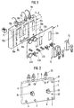
- the inventive Setting up a plate-shaped body 1 made of plastic or metal with a rectangular cross-section and a thickness d.
- the Base body 1 On one plate surface, which is defined as the front 2, the Base body 1 a plurality of groove-shaped elongated and each parallel to one of the outer edges of the base body 1 extending recesses or cutouts 10a, 10b, 10c ... on which individual channel sections of flow channels form for a liquid flowing in the base body 1.
- the recesses 10a, 10b, 10c, ... have a rectangular shape or circular cross-section.
- the basic body is made of gunmetal or glass fiber reinforced plastic, made of brass (MS), polypropylene random (PP-R) or VA educated. When using MS or gunmetal and highly concentrated The basic body is suitable for the medium refined or coated.
- the base body 1 also has in addition to the groove-shaped Recesses 10a, 10b ..., which the flow channels form, on its front 2 a number of others Recesses 12a, 12b, 12c with a rectangular cross section on, the edges of which are parallel to the outer edges of the base body 1 are aligned.
- the recesses 12a, 12b, 12c serve to accommodate appropriately dimensioned push elements or receiving bodies 13 for instruments.
- the base body instructs its rear surface 3 opposite the front side 2 a plurality of connections A, B, C, D, E, F, G, H on, through openings in defined positions in the back surface 3 are formed.
- the connections serve as liquid or transfers.
- connections 31, 32, 33, 34 at predetermined positions for measuring and Control devices provided.
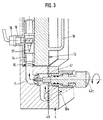
- a receiving body is in each case in the recesses 12a, 12b, 12c 13 with an outline corresponding to the recess for a functional element for steering, control, regulation or monitoring the liquid flow.
- the receiving body 13 a flow channel running vertically in the inserted position 14, which at its ends with predetermined Channel sections on the surface 2 of the base body 1 via flow channels provided in the interior of the base body 11 communicates.
- FIG. 3 shown receiving body 13 for connecting the in Fig. 1 shown recesses or channel sections 10e and 10d.
- the flow channel 14 of the receiving body 13 is at its connection point to the base body 1 via a Seal in the form of a rubber ring 15 against leakage Liquid sealed to the environment.
- the receiving body 13 has in its inserted position the front facing rear surface a tubular extension 16 on the through on the back surface 3 of the base body 1 provided opening extends through and over the opening in the rear surface 3 with the flow channel 14 in connection stands.
- the receiving body 13 has a turbine 17 in it
- Flow channel 14 is on and at the rear approach a sensor 18 is provided.
- the Receiving body on its opposite the approach 16 Side a handle 19 with which it is in the recess inserted and pulled out again can.
- the recesses 10a, 10b, 10c, ... are on the front of the base body via the receiving body 13, the flow channels 11 provided inside the base body and the connections provided on the back to one defined channel system connected.
- a front plate 4 is provided, which the same Outline of how the base body 1 has and that on the base body detachable but non-rotatable relative to this, for example fixed by screws.
- the front plate 4 covers the recesses 10a, 10b, 10c ... being between the front panel 4 and the edge the recesses 10a, 10b, 10c ... each have a seal 40 to prevent liquid from escaping from the channel sections 10a, 10b, 10c, ... is provided.
- the seal is designed for example in the form of rubber sealing rings.
- the front plate 4 also has a plurality of openings 41 at predetermined positions, in which functional elements 42a, 42b, 42c, ... for steering, control, regulation and monitoring of through the flow channels of the base body flowing water, such as control valves, Control valves, check valves, pressure gauges, pressure switches, Flow meters and conductivity meters as well Sample taps are attached.
- functional elements 42a, 42b, 42c, ... for steering, control, regulation and monitoring of through the flow channels of the base body flowing water, such as control valves, Control valves, check valves, pressure gauges, pressure switches, Flow meters and conductivity meters as well Sample taps are attached.
- Fig. 1 represents the functional element with the reference numeral 42a a manometer
- Functional element with the reference numeral 42b a sample tap
- the functional element with the reference symbol 42c is a valve represents.
- the front plate 4 has a plurality of openings 43a, 43b, 43c corresponding to the recesses 12a, 12b, 12c of the base body 1 through which the receiving body 13 even with the front panel 4 attached by pulling it out and Insert can be replaced.
- the base body 1 has between the Front 2 and rear 3 lying top 5 further openings, which with the channel system in the base body are connected and in the conductivity sensors, for example 51 are used or the one Have actuator 52, which the receiving body 13th fixed.
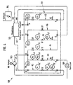
- a membrane technical water treatment plant according to the invention 100 is shown in FIG. 4.
- the water treatment plant has a device 101 for steering, Control, regulation and monitoring of liquid flows on, which will be referred to as control block 101.
- the water treatment system also has a membrane 102 with an input M1 and two outputs M2 and M3 for the Liquid on.
- To achieve one for the overflow the membrane 102 necessary fluid pressure is one High pressure pump 103 with an input P1 and an output P2 provided.
- Required electrical facilities for the system is provided in a separate electrical cabinet 104.
- To pre-filter the incoming raw water is a Fine filter 105 provided.
- the control block 101 has four inputs C, A, E and G as well four outputs D, B, F, H on.
- the entrance A stands with the Output B via one provided in the control block 101
- Flow channel K1 in connection the flow channel one after the other between input A and output B has the following instruments or elements: a sample tap 3A, a solenoid valve 2A, a pressure switch 5A Pressure gauge 4A and a conductivity probe 8A.
- the exit B is connected to the input P1 of the pump 103 and the output P2 of the pump 103 is connected to the input C.
- the input C in the control block 101 is over a flow channel K2 connected to the outlet D.
- Flow channels K2 are consecutive between the entrance C and the output D arranged the following instruments: a pressure switch 5C, a pressure manometer 4C, a setting valve 1C and another pressure manometer 4C '.
- the output D is connected to the input M1 of the membrane 102.
- the permeate discharge outlet M3 of the membrane 102 is connected to input G of control block 101.
- the input G is provided in the control block 101
- Flow channel K3 connected to the output H.
- In the channel K3 are successive between G and H following Instruments arranged: a sample tap 3G, a flow meter 7G, a check valve 6G and a conductivity probe 8G.
- Channel K3 is used for monitoring and derivation of the permeate emerging from the outlet M3 of the membrane as a cleaned product.
- the outlet M2 of the membrane 102 that discharges the concentrate is connected to input E of the control block.
- the entrance E of the control block is over one in the control block 101 provided flow channel K4 connected to the output B.
- the following are between input E and output B Instruments arranged one after the other: a setting valve 1E, a flow meter 7E and a check valve 6E.
- Channel K4 is used to return a part of the concentrate leaving the exit M2 of the membrane via the pump 103 into the membrane 102.
- the input E of the control block 101 is with the output F via a channel K5 provided in the control block connected.
- a channel K5 provided in the control block connected.
- the following instruments are provided in succession: a Sample valve 3F, a pressure manometer 4F, a setting valve 1F, a flow meter 7F, a check valve 6F and one Conductivity probe 8F.
- Channel K5 is used for drainage of a part of the membrane leaving the exit M2 Concentrate as residual water.
- the input E is via another, in the control block 101 formed channel K6 connected to the output F, a solenoid valve 2F being provided in the channel K6 is.
- Channel K6 is required if the membrane ends after production or flushed with raw water after a fault becomes.
- the control block 101 is like that in FIGS. 1 to 3 shown embodiment formed. That means, that all channels on the surface or within the body run.
- the connections of the control block are provided on the back of the body, while the Control, regulation and monitoring elements on the front are provided and thus clear and easily accessible are arranged for an operator.
- the operation the membrane water treatment plant will be in following described with reference to FIG. 4.
- the filtered through fine filter 105 flows Raw water above that on the back of control block 101 provided connection A in the main body of the control block and passes the instruments provided in channel K1, namely the sample tap 3A, the solenoid valve 2A, the Pressure gauge 4A and the pressure switch 5A.
- the raw water leaves the control block at exit B as mixed water in Direction of high pressure pump 103, the necessary operating pressure builds up.
- This mixed water occurs at port C on the back the control block back into the base body.
- Supervised and preset by pressure switch 5C, the pressure gauge 4C, the adjusting valve 1C, the other pressure gauge 4C 'and the conductivity probe 8A come under pressure set mixed water via outlet D on the back the control block into the membrane 102.
- the membrane separates the mixed water in two different qualities and quantities. A part flows as a product through the outlet M3 the membrane in the provided on the back of the control block Port G in the base body is over the Sample tap 3G, the flow meter 7G, the check valve 6G and the conductivity probe 8G checked and leaves the base at output H on the rear of the control block for further use.
- the second, leaving the membrane at the exit M2 as a concentrate Part flows into the base body at connection E. and is again divided into two different streams.
- the main flow is via channel K4, via the adjusting valve 1E, the flow meter 7E and the reset valve 6E the raw water to secure the discharge on the Membrane 102 supplied.
- This repatriation of part of the Concentrate is needed to keep the flow rate up keep the membrane constant so the membrane does not Filter effect shows. The yield can thus be increased to around 75% increase.
- the smaller part of the concentrate is channel K5 via the sample tap 3F, the pressure gauge 4F, the adjusting valve 1F, the flow meter 7F, the check valve 6F and the conductivity probe 8F via the output F on the Drained back of the control block to not the system to block. This residual water is fed into the sewer.
- the membrane 102 via the connection E, the output F and the channel K6 with the Solenoid valve 2F rinsed free with raw water.
- control device or the control block also for other membrane technical water treatment plants can be used, for example for nanofiltration systems, Ultrafiltration systems and microfiltration systems.
- the described is particularly suitable Control system for medium-sized plants with approx. 600 to 2000 l / h Product quantity but also for small plants with approx. 50 to 500 l / h product quantity.
Landscapes
- Water Supply & Treatment (AREA)
- Chemical & Material Sciences (AREA)
- Engineering & Computer Science (AREA)
- Organic Chemistry (AREA)
- Environmental & Geological Engineering (AREA)
- Hydrology & Water Resources (AREA)
- Life Sciences & Earth Sciences (AREA)
- Nanotechnology (AREA)
- Chemical Kinetics & Catalysis (AREA)
- Separation Using Semi-Permeable Membranes (AREA)
- Steering Control In Accordance With Driving Conditions (AREA)
- Control Of Non-Electrical Variables (AREA)
- Flow Control (AREA)
Abstract
Description
Die Erfindung betrifft eine Einrichtung zur Lenkung, Steuerung, Messung und Überwachung von Flüssigkeitsströmen, insbesondere für eine membrantechnische Wasseraufbereitungsanlage, und eine Wasseraufbereitungsanlage.The invention relates to a device for steering, control, Measurement and monitoring of liquid flows, especially for a membrane technical water treatment plant, and a water treatment plant.
In einer membrantechnischen Wasseraufbereitungsanlage, beispielsweise einer nach dem Prinzip der Umkehr-Osmose arbeitenden Wasseraufbereitungsanlage, wird Rohwasser mit Hochdruck über eine synthetische Membran geleitet. Die in dem Wasser vorhandenen Inhaltsstoffe werden von der Membran selektiv zurückgehalten, wodurch eine Auftrennung in reines Wasser (Permeat) und die zurückgehaltenen Inhaltsstoffe enthaltendes Wasser (Konzentrat) erfolgt. In a membrane water treatment plant, for example one working on the principle of reverse osmosis Water treatment plant, raw water becomes high pressure passed over a synthetic membrane. The one in the Ingredients present in water are removed from the membrane selectively retained, causing a separation into pure Water (permeate) and the retained ingredients containing water (concentrate).
Es sind membrantechnische Wasseraufbereitungsanlagen bekannt, in denen die Flüssigkeitsströme durch Rohre gelenkt werden, wobei die zur Steuerung, Regelung und Überwachung erforderlichen Funktionselemente, wie Regelventile, Steuerventile, Drucksensoren, Druckschalter, Strömungsmesser und ähnliches jeweils in das Rohrsystem über Schraubverbindungen fest eingebaut sind.Membrane water treatment plants are known in which the fluid flows are directed through pipes be used for control, regulation and monitoring required functional elements, such as control valves, control valves, Pressure sensors, pressure switches, flow meters and similar in each case in the pipe system via screw connections are permanently installed.
Dieser herkömmliche Aufbau weist den Nachteil auf, daß die Montagezeit für den Aufbau unverhältnismäßig groß ist und der Aufbau insgesamt sehr viel Platz einnimmt. Ferner ist das Auswechseln von einzelnen Funktionselementen oder das Einfügen zusätzlicher Funktionselemente kompliziert und unter Umständen nur mit einer Änderung des gesamten Aufbaus zu realisieren. This conventional structure has the disadvantage that the Assembly time for the construction is disproportionately large and the overall structure takes up a lot of space. Further is the replacement of individual functional elements or the Inserting additional functional elements complicated and under Under certain circumstances only with a change in the entire structure to realize.
Aus der EP-A-0 272 632 ist eine Einrichtung zur Steuerung, Regelung, Messung und Überwachung von Flüssigkeitsströmen für eine Wasseraufbereitungsanlage gemäß dem Oberbegriff des Anspruches 1 bekannt.EP-A-0 272 632 describes a device for controlling, regulating, Measurement and monitoring of liquid flows for one Water treatment plant according to the preamble of the claim 1 known.
Aus der EP-A-0 347 297 ist ein Steuerventil für ein Umkehrosmose-Wasserreinigungssystem bekannt.From EP-A-0 347 297 is a control valve for a reverse osmosis water purification system known.
Aufgabe der Erfindung ist es, eine Einrichtung zur Lenkung, Steuerung und Überwachung von Flüssigkeitsströmen, insbesondere für eine membrantechnische Wasseraufbereitungsanlage, eine Verwendung einer solchen Einrichtung und eine Wasseraufbereitungsanlage bereitzustellen, welche platzsparend und kompakt aufgebaut sind, eine geringe Montage- und Reparaturzeit erfordert und darüber hinaus bei vielseitigen Einsatzmöglichkeiten auch einfach zu bedienen sind.The object of the invention is to provide a device for steering, Control and monitoring of liquid flows, in particular for a membrane technical water treatment plant, one use such a facility and a water treatment plant to provide which is space-saving and compact are a short assembly and repair time required and also with a wide range of applications are easy to use.
Die Aufgabe wird gelöst durch die Einrichtung nach Patentanspruch
1, die Verwendung nach Patentanspruch 12 oder durch die
Wasseraufbereitungsanlage nach Patentanspruch 13.The object is achieved by the device according to claim
1, the use according to claim 12 or by the
Water treatment plant according to
Weiterbildungen der Erfindung sind in den Unteransprüchen angegeben.Developments of the invention are specified in the subclaims.
Weitere Merkmale und Zweckmäßigkeiten ergeben sich aus der Beschreibung von Ausführungsbeispielen der Erfindung in Zusammenhang mit den Figuren. Von den Figuren zeigen:
- Fig. 1
- eine perspektivische Darstellung der erfindungsgemäßen Einrichtung mit explosionsmäßig auseinandergezogenen Einzelteilen von der Vorderseite gesehen;
- Fig. 2
- eine perspektivische Darstellung der erfindungsgemäßen Einrichtung von der Rückseite gesehen;
- Fig. 3
- eine teilweise geschnittene Darstellung eines Ausschnittes der erfindungsgemäßen Vorrichtung und
- Fig. 4
- eine schematische Darstellung einer membrantechnischen Wasseraufbereitungsanlage mit einer schematischen Darstellung des Verlaufs der Strömungskanäle.
- Fig. 1
- a perspective view of the device according to the invention seen with exploded individual parts from the front;
- Fig. 2
- a perspective view of the device according to the invention seen from the rear;
- Fig. 3
- a partially sectioned illustration of a section of the device according to the invention and
- Fig. 4
- is a schematic representation of a membrane technology water treatment plant with a schematic representation of the course of the flow channels.
Wie aus den Figuren 1 bis 3 ersichtlich ist, weist die erfindungsgemäße
Einrichtung einen plattenförmigen Grundkörper
1 aus Kunststoff oder Metall mit rechteckigem Querschnitt
und einer Dicke d auf. An seiner einen Plattenoberfläche,
die als Vorderseite 2 definiert wird, weist der
Grundkörper 1 eine Mehrzahl von nutförmigen länglichen und
jeweils parallel zu einer der Außenkanten des Grundkörpers
1 verlaufende Ausnehmungen bzw. Ausfräsungen 10a, 10b, 10c
... auf, welche einzelne Kanalabschnitte von Strömungskanälen
für eine im Grundkörper 1 strömende Flüssigkeit bilden.
Die Ausnehmungen 10a, 10b, 10c,... weisen rechteckförmigen
oder kreisabschnittförmigen Querschnitt auf. Der Grundkörper
ist aus Rotguß oder glasfaserverstärktem Kunststoff,
aus Messing (MS), Polypropylen-Random (PP-R) oder VA
gebildet. Beim Einsatz von MS bzw. Rotguß und hochkonzentrierten
Wässern ist der Grundkörper mediumsgerecht
veredelt bzw. beschichtet.As can be seen from Figures 1 to 3, the inventive
Setting up a plate-shaped body
1 made of plastic or metal with a rectangular cross-section
and a thickness d. On one plate surface,
which is defined as the
Der Grundkörper 1 weist ferner zusätzlich zu den nutförmigen
Ausnehmungen 10a, 10b ..., welche die Strömungskanäle
bilden, an seiner Vorderseite 2 eine Anzahl von weiteren
Ausnehmungen 12a, 12b, 12c mit rechteckigem Querschnitt
auf, deren Kanten parallel zu den Außenkanten des Grundkörpers
1 ausgerichtet sind. Die Ausnehmungen 12a, 12b, 12c
dienen zur Aufnahme von passend dimensionierten Schubelementen
bzw. Aufnahmekörpern 13 für Instrumente.The base body 1 also has in addition to the groove-
Wie aus Fig. 2 ersichtlich ist, weist der Grundkörper an
seiner der Vorderseite 2 gegenüberliegenden Rückfläche 3
eine Mehrzahl von Anschlüssen A, B, C, D, E, F, G, H auf,
die durch Öffnungen an definierten Positionen in der Rückfläche
3 gebildet sind. Die Anschlüsse dienen als Flüssigkeitszu-
bzw. Abführungen.As can be seen from Fig. 2, the base body instructs
its
Ferner sind an der Rückfläche noch Anschlüsse 31, 32, 33,
34 an vorgegebenen Positionen für anzubringende Meß- und
Regelgeräte vorgesehen.Furthermore,
In den Ausnehmungen 12a, 12b, 12c ist jeweils ein Aufnahmekörper
13 mit einem der Ausnehmung entsprechendem Umriß
für ein Funktionselement zur Lenkung, Steuerung, Regelung
oder Überwachung des Flüssigkeitsstromes eingesetzt. Wie
aus Fig. 3 ersichtlich ist, weist der Aufnahmekörper 13
einen in eingesetzter Position vertikal verlaufenden Strömungskanal
14 auf, welcher an seinen Enden mit vorbestimmten
Kanalabschnitten an der Oberfläche 2 des Grundkörpers 1
über im Inneren des Grundkörpers vorgesehene Strömungskanäle
11 in Verbindung steht. Beispielsweise dient der in
Fig. 3 dargestellte Aufnahmekörper 13 zur Verbindung der in
Fig. 1 dargestellten Ausnehmungen bzw. Kanalabschnitte 10e
und 10d. Der Strömungskanal 14 des Aufnahmekörpers 13 ist
an seiner Verbindungsstelle zum Grundkörper 1 über eine
Dichtung in Form eines Gummirings 15 gegen Austreten von
Flüssigkeit in die Umgebung abgedichtet. Der Aufnahmekörper
13 weist an seiner in eingesetzter Position der Vorderseite
abgewandten Rückfläche einen rohrförmigen Ansatz 16 auf der
sich durch eine auf der Rückfläche 3 des Grundkörpers 1
vorgesehene Öffnung hindurcherstreckt und über den die Öffnung
in der Rückfläche 3 mit dem Strömungskanal 14 in Verbindung
steht. In dem in Fig. 3 gezeigten Ausführungsbeispiel
weist der Aufnahmekörper 13 eine Turbine 17 in seinem
Strömungskanal 14 auf und an dem rückwärtigen Ansatz ist
ein Sensor 18 vorgesehen. Je nach Bedarf können aber auch
Aufnahmekörper mit anderen Funktionselementen zur Steuerung,
Regelung und Überwachung des Flüssigkeitsstromes vorgesehen
sein, beispielsweise mit anderen Typen von Ventilen,
Turbinen oder Sensoren. Zweckmäßigerweise weist der
Aufnahmekörper an seiner dem Ansatz 16 gegenüberliegenden
Seite einen Haltegriff 19 auf mit der er in die Ausnehmung
eingeschoben und wieder aus dieser herausgezogen werden
kann.A receiving body is in each case in the
Somit sind die Ausnehmungen 10a, 10b, 10c, ... auf der Vorderseite
des Grundkörpers über die Aufnahmekörper 13, die
im Inneren des Grundkörpers vorgesehenen Strömungskanäle 11
und die auf der Rückseite vorgesehenen Anschlüsse zu einem
definierten Kanalsystem verbunden.Thus, the
Wie aus Fig. 2 ersichtlich ist, ist über der die Ausnehmungen
10a, 10b, 10c ... aufweisenden Vorderseite 2 des Grundkörpers
1 eine Frontplatte 4 vorgesehen, welche denselben
Umriß wie der Grundkörper 1 aufweist und die an dem Grundkörper
lösbar aber drehfest gegenüber diesem, beispielsweise
durch Schrauben, befestigt ist.As can be seen from Fig. 2, the recesses are above
10a, 10b, 10c
Die Frontplatte 4 überdeckt dabei die Ausnehmungen 10a,
10b, 10c ... wobei zwischen der Frontplatte 4 und dem Rand
der Ausnehmungen 10a, 10b, 10c ... jeweils eine Dichtung 40
zum Verhindern eines Flüssigkeitsaustrittes aus den Kanalabschnitten
10a, 10b, 10c, ... vorgesehen ist. Die Dichtung
ist beispielsweise in Form von Gummidichtringen ausgebildet. The
Die Frontplatte 4 weist ferner eine Mehrzahl von Öffnungen
41 an vorgegebenen Positionen auf, in welchen Funktionselemente
42a, 42b, 42c, ... zur Lenkung, Steuerung, Regelung
und Überwachung von durch die Strömungskanäle des Grundkörpers
fließenden Wasser, wie beispielsweise Steuerventile,
Regelventile, Rückschlagventile, Druckmanometer, Druckschalter,
Strömungsmesser und Leitfähigkeitsmesser sowie
Probehähne angebracht sind. In Fig. 1 stellt das Funktionselement
mit dem Bezugszeichen 42a ein Manometer, das
Funktionselement mit dem Bezugszeichen 42b einen Probehahn
und das Funktionselement mit dem Bezugszeichen 42c ein Ventil
dar.The
Ferner weist die Frontplatte 4 eine Mehrzahl von Öffnungen
43a, 43b, 43c in Entsprechung zu den Ausnehmungen 12a, 12b,
12c des Grundkörpers 1 auf, durch die die Aufnahmekörper 13
auch bei befestigter Frontplatte 4 durch Herausziehen und
Einschieben ausgewechselt werden können.Furthermore, the
Zusätzlich weist der Grundkörper 1 an seiner zwischen der
Vorderseite 2 und der Rückseite 3 liegenden Oberseite 5
weitere Öffnungen auf, welche mit dem Kanalsystem im Grundkörper
in Verbindung stehen und in die beispielsweise Leitfähigkeitsmeßsonden
51 eingesetzt sind oder die ein
Stellglied 52 aufweisen, welches den Aufnahmekörper 13
fixiert.In addition, the base body 1 has between the
Eine erfindungsgemäße membrantechnische Wasseraufbereitungsanlage
100 ist in Fig. 4 dargestellt. Die Wasseraufbereitungsanlage
weist eine Einrichtung 101 zur Lenkung,
Steuerung, Regelung und Überwachung der Flüssigkeitsströme
auf, die im weiteren als Steuerblock 101 bezeichnet wird.
Ferner weist die Wasseraufbereitungsanlage eine Membran 102
mit einem Eingang M1 und zwei Ausgängen M2 und M3 für die
Flüssigkeit auf. Zum Erreichen eines für die Überströmung
der Membran 102 notwendigen Flüssigkeitsdrucks ist eine
Hochdruck-Pumpe 103 mit einem Eingang P1 und einem Ausgang
P2 vorgesehen. Erforderlich elektrische Einrichtungen für
die Anlage sind in einem separaten E-Schrank 104 vorgesehen.
Zum Vorfiltern des eintretenden Rohwassers ist ein
Feinfilter 105 vorgesehen.A membrane technical water treatment plant according to the
Der Steuerblock 101 weist vier Eingänge C, A, E und G sowie
vier Ausgänge D, B, F, H auf. Der Eingang A steht mit dem
Ausgang B über einen in dem Steuerblock 101 vorgesehenen
Strömungskanal K1 in Verbindung, wobei der Strömungskanal
der Reihe nach zwischen dem Eingang A und dem Ausgang B
folgende Instrumente bzw. Elemente aufweist: einen Probehahn
3A, ein Magnetventil 2A, einen Druckschalter 5A, ein
Druckmanometer 4A und eine Leitfähigkeitssonde 8A. Der Ausgang
B ist mit dem Eingang P1 der Pumpe 103 verbunden und
der Ausgang P2 der Pumpe 103 ist mit dem Eingang C verbunden.
Ferner ist der Eingang C in dem Steuerblock 101 über
einen Strömungskanal K2 mit dem Ausgang D verbunden. In dem
Strömungskanal K2 sind aufeinanderfolgend zwischen dem Eingang
C und dem Ausgang D folgende Instrumente angeordnet:
ein Druckschalter 5C, ein Druckmanometer 4C, ein Einstellventil
1C und ein weiteres Druckmanometer 4C'.The
Der Ausgang D ist mit dem Eingang M1 der Membran 102 verbunden.
Der das Permeat ableitende Ausgang M3 der Membran
102 ist mit dem Eingang G des Steuerblocks 101 verbunden.
Der Eingang G ist über einen in dem Steuerblock 101 vorgesehenen
Strömungskanal K3 mit dem Ausgang H verbunden. In
dem Kanal K3 sind aufeinanderfolgend zwischen G und H folgende
Instrumente angeordnet: ein Probehahn 3G, Ein Strömungsmesser
7G, ein Rückschlagventil 6G und eine Leitfähigkeitssonde
8G. Der Kanal K3 dient zum Überwachen und Ableiten
des aus dem Ausgang M3 der Membran austretenden Permeats
als gereinigtes Produkt.The output D is connected to the input M1 of the
Der das Konzentrat ableitenden Ausgang M2 der Membran 102
ist mit dem Eingang E des Steuerblocks verbunden. Der Eingang
E des Steuerblocks ist über einen in dem Steuerblock
101 vorgesehenen Strömungskanal K4 mit dem Ausgang B verbunden.
Zwischen dem Eingang E und dem Ausgang B sind folgende
Instrumente aufeinanderfolgend angeordnet: ein Einstellventil
1E, ein Strömungsmesser 7E und ein Rückschlagventil
6E. Der Kanal K4 dient zum Rückführen eines Teiles
des den Ausgang M2 der Membran verlassenden Konzentrats
über die Pumpe 103 in die Membran 102.The outlet M2 of the
Ferner ist der Eingang E des Steuerblocks 101 mit dem Ausgang
F über einen in dem Steuerblock vorgesehenen Kanal K5
verbunden. Zwischen dem Eingang E und dem Ausgang F sind
folgende Instrumente aufeinanderfolgend vorgesehen: ein
Probehahn 3F, ein Druckmanometer 4F, ein Einstellventil 1F,
ein Strömungsmesser 7F, eine Rückschlagventil 6F und eine
Leitfähigkeitssonde 8F. Der Kanal K5 dient zum Ableiten
eines Teiles des die Membran am Ausgang M2 verlassenden
Konzentrats als Restwasser.Furthermore, the input E of the
Ferner ist der Eingang E über einen weiteren, in dem Steuerblock 101 gebildeten Kanal K6 mit dem Ausgang F verbunden, wobei in dem Kanal K6 ein Magnetventil 2F vorgesehen ist. Der Kanal K6 wird benötigt, wenn die Membran nach Produktionsende oder nach einer Störung mit Rohwasser freigespült wird.Furthermore, the input E is via another, in the control block 101 formed channel K6 connected to the output F, a solenoid valve 2F being provided in the channel K6 is. Channel K6 is required if the membrane ends after production or flushed with raw water after a fault becomes.
Der Steuerblock 101 ist wie in dem in den Figuren 1 bis 3
gezeigten Ausführungsbeispiel ausgebildet. Das bedeutet,
daß alle Kanäle an der Oberfläche oder innerhalb des Grundkörpers
verlaufen. Die Anschlüsse des Steuerblockes sind
auf der Rückseite des Grundkörpers vorgesehen, während die
Steuer-, Regel- und Überwachungselemente an der Vorderseite
vorgesehen sind und somit übersichtlich und leicht zugänglich
für eine Bedienungsperson angeordnet sind. Der Betrieb
der membrantechnischen Wasseraufbereitungsanlage wird im
folgenden anhand von Fig. 4 beschrieben.The
Im Betrieb strömt das über den Feinfilter 105 filtrierte
Rohwasser über den auf der Rückseite des Steuerblocks 101
vorgesehenen Anschluß A in den Grundkörper des Steuerblocks
ein und passiert die in dem Kanal K1 vorgesehenen Instrumente,
nämlich den Probehahn 3A, das Magnetventil 2A, das
Druckmanometer 4A und den Druckschalter 5A. Das Rohwasser
verläßt den Steuerblock bei Ausgang B als Mischwasser in
Richtung der Hochdruckpumpe 103, die den notwendigen Betriebsdruck
aufbaut.In operation, the filtered through
Dieses Mischwasser tritt bei Anschluß C auf der Rückseite
des Steuerblocks wieder in den Grundkörper ein. Überwacht
und voreingestellt durch Druckschalter 5C, das Druckmanometer
4C, das Einstellventil 1C, das weitere Druckmanometer
4C' und die Leitfähigkeitssonde 8A gelangt das auf Druck
eingestellt Mischwasser über den Ausgang D auf der Rückseite
des Steuerblocks in die Membran 102.This mixed water occurs at port C on the back
the control block back into the base body. Supervised
and preset by
Die Membran trennt das Mischwasser in zweierlei Qualitäten
und Mengen. Ein Teil strömt als Produkt über den Ausgang M3
der Membran in den auf der Rückseite des Steuerblocks vorgesehenen
Anschluß G in den Grundkörper ein, wird über den
Probehahn 3G, den Strömungsmesser 7G, das Rückschlagventil
6G und die Leitfähigkeitssonde 8G kontrolliert und verläßt
am Ausgang H auf der Rückseite des Steuerblocks den Grundkörper
zur weiteren Verwendung.The membrane separates the mixed water in two different qualities
and quantities. A part flows as a product through the outlet M3
the membrane in the provided on the back of the control block
Port G in the base body is over the
Der zweite, die Membran am Ausgang M2 als Konzentrat verlassende Teil strömt am Anschluß E in den Grundkörper ein und wird wiederum in zwei unterschiedliche Ströme aufgeteilt. The second, leaving the membrane at the exit M2 as a concentrate Part flows into the base body at connection E. and is again divided into two different streams.
Der Hauptstrom wird über den Kanal K4, über das Einstellventil
1E, den Strömungsmesser 7E und das Rückstellventil
6E dem Rohwasser zur Sicherung der Abströmmenge auf der
Membran 102 zugeführt. Diese Rückführung eines Teiles des
Konzentrates ist nötig, um die Abströmgeschwindigkeit auf
der Membran konstant zu halten, damit die Membran keine
Filterwirkung zeigt. Damit kann die Ausbeute auf etwa 75 %
erhöht werden.The main flow is via channel K4, via the adjusting
Der kleinere Teil des Konzentrates wird durch den Kanal K5
über den Probehahn 3F, das Druckmanometer 4F, das Einstellventil
1F, den Strömungsmesser 7F, das Rückschlagventil 6F
und die Leitfähigkeitssonde 8F über den Ausgang F auf der
Rückseite des Steuerblocks abgelassen, um das System nicht
zu verblocken. Dieses Restwasser wird dem Abwasserkanal zugeführt.The smaller part of the concentrate is channel K5
via the
Wenn die membrantechnische Anlage bei Produktionsende oder
bei einer Störung angehalten wird, wird die Membran 102
über den Anschluß E, den Ausgang F und den Kanal K6 mit dem
Magnetventil 2F mit Rohwasser freigespült.If the membrane technology plant at the end of production or
stopped in the event of a fault, the
Wie sich aus der obigen Beschreibung ergibt, liegt ein wesentlicher Vorteil der beschriebenen Anlage in ihrer kompakten Bauweise, die insbesondere auch durch das Vorsehen der Aufnahmekörper für Funktionseinheiten in Form der Schubelemente eine leichte Auswechselbarkeit der Meß-, Regeloder Steuerinstrumente erlaubt. Das Vorsehen der Regel- und Steuerelemente, die von einem Bediener einzustellen sind, auf der Frontseite in übersichtlicher Form erlaubt eine leichte Bedienung durch einen Anwender. Beim Design eines Kanalsystems können schon bestimmte zusätzliche Schleifen vorgesehen sein, die dann über den Einsatz von Ventilen für spezielle Anwendungen in Betrieb genommen werden können oder nicht. As can be seen from the above description, there is an essential one Advantage of the system described in its compact Construction, in particular by the provision the receiving body for functional units in the form of the push elements an easy interchangeability of the measuring, control or Tax instruments allowed. The provision of regular and Controls to be set by an operator on the front in a clear form allows one easy operation by a user. When designing a Channel systems can do certain additional loops be provided, which then on the use of valves for special applications can be put into operation or not.
Dadurch ist die oben beschriebene Steuervorrichtung bzw. der Steuerblock auch für andere membrantechnische Wasseraufbereitungsanlagen einsetzbar, beispielsweise für Nanofiltrationsanlagen, Ultrafiltrationsanlagen und Mikrofiltrationsanlagen. Besonders geeignet ist das beschriebene Steuersystem für mittlere Anlagen mit ca. 600 bis 2000 l/h Produktmenge aber auch für Kleinanlagen mit ca. 50 bis 500 l/h Produktmenge.As a result, the control device or the control block also for other membrane technical water treatment plants can be used, for example for nanofiltration systems, Ultrafiltration systems and microfiltration systems. The described is particularly suitable Control system for medium-sized plants with approx. 600 to 2000 l / h Product quantity but also for small plants with approx. 50 to 500 l / h product quantity.
Claims (13)
- Device for controlling, regulating, measuring and monitoring liquid flows for a water treatment plant, having a unit (1, 4) with, provided in the unit, cutouts (10a, 10b, 10c, ...) forming channel sections for a flowing liquid and having an inflow and outflow (A, B, C, D, E, F, G, H), connected to the channel sections, for the liquid, at least one functional element (42a, 42b, 42c, 18, 19) being provided to steer, control, regulate or monitor the liquid flowing in the channel sections, characterized in that the unit (1, 4) comprises a first plate-shaped body (1) having a surface (2) and a second plate-shaped body (4) connected to the first body in a manner fixed in rotation and sealingly shutting off the cutouts (10a, 10b, 10c, ...) from the environment, the cutouts (10a, 10b, 10c, ...) being provided on the surface (2) of the first plate-shaped body (1).
- Device according to Claim 1, characterized in that the first body additionally comprises cavities in the form of channels (11) extending in its interior.
- Device according to Claim 2, characterized in that the first body (1) comprises, on a side facing away from the surface, apertures (A, B, C, D, E, F, G, H) for the inflow and outflow which are in connection with the cutouts (10a, 10b, 10c, 10d, ...).
- Device according to Claim 3, characterized in that the cutouts (10a, 10b, 10c, ...) on the surface, the flow channels (11) in the interior and the apertures (A, B, C ...) form the channel system for the liquid.
- Device according to one of Claims 1 to 4, characterized in that the second body (4) comprises at least one aperture which is in connection with one of the cutouts (10a, 10b, 10c ...) on the surface of the first body and in which a first functional element (42a, 42b, 42c) for controlling, regulating or monitoring a flowing liquid is provided.
- Device according to one of Claims 1 to 5, characterized in that the first body is produced from a casting.
- Device according to one of Claims 1 to 6, characterized in that the first body comprises at least one further cutout (12a, 12b, 12c) on the surface in which a receiving body (13) containing a second functional element for controlling, regulating and/or monitoring the flowing liquid can be inserted.
- Device according to Claim 7, characterized in that the receiving body (13) can be inserted into the cutout and removed again therefrom via an aperture (43a, 43b, 43c) provided in the second body (4) and having a cross section corresponding to the cutout (12a, 12b, 12c).
- Device according to Claim 7 or 8, characterized in that a connection point between the receiving body and the first body (1) is sealed to prevent an escape of liquid.
- Device according to one of Claims 1 to 9, characterized in that the first body (1) is designed in the form of a plate having a defined thickness (d) and in that the second body (4) is likewise designed as a plate having a thickness which is less than the thickness of the first body.
- Device according to one of Claims 5 to 10, characterized in that the functional elements comprise control valves, pressure manometers, pressure switches, flow meters, control valves, nonreturn valves and/or conductivity probes.
- Use of a device according to one of Claims 1 to 10 as a control unit in a water treatment plant using membrane technology.
- Water treatment plant having a membrane (102) with an inlet (M1), a first outlet (M2) and a second outlet (M3), a pump (103) and a control device (101) with a first (A), a second (C), a third (G) and a fourth (E) inlet and with a first (B), a second (D), a third (H) and a fourth (F) outlet, the first inlet (A) being connected via a first channel (K1) to the first outlet (B), the second inlet (C) via a second channel (K2) to the second outlet (D), the third inlet (G) via a third channel (K3) to the third outlet (H) and the fourth inlet (E) via a fourth channel (K4) to the first outlet (B), and via a fifth channel (K5) to the fourth outlet (F), and the first outlet (D) being connected via the pump (103) to the second inlet (C), the second outlet (D) to the inlet (M1) of the membrane (102), and the first outlet (M2) of the membrane to the fourth inlet (E) and the second outlet (M3) of the membrane to the third inlet (G), the control device (101) being designed as a unit and at least one functional element (42a, 42b, 42c, 18, 19) being provided to steer, control, regulate or monitor the liquid flowing in the channels, the unit having a base body comprising the channels and a plate masking the channels.
Applications Claiming Priority (3)
| Application Number | Priority Date | Filing Date | Title |
|---|---|---|---|
| DE19704656 | 1997-02-07 | ||
| DE19704656A DE19704656A1 (en) | 1997-02-07 | 1997-02-07 | Device for steering, control, regulation, measurement and monitoring of liquid flows and water treatment system |
| PCT/EP1998/000372 WO1998034717A1 (en) | 1997-02-07 | 1998-01-23 | Device for controlling, guiding, adjusting, measuring and monitoring liquid flows, and water treatment facility |
Publications (2)
| Publication Number | Publication Date |
|---|---|
| EP0902722A1 EP0902722A1 (en) | 1999-03-24 |
| EP0902722B1 true EP0902722B1 (en) | 2001-08-16 |
Family
ID=7819598
Family Applications (1)
| Application Number | Title | Priority Date | Filing Date |
|---|---|---|---|
| EP98904129A Expired - Lifetime EP0902722B1 (en) | 1997-02-07 | 1998-01-23 | Device for controlling, guiding, adjusting, measuring and monitoring liquid flows, and water treatment facility |
Country Status (8)
| Country | Link |
|---|---|
| US (1) | US6136196A (en) |
| EP (1) | EP0902722B1 (en) |
| JP (1) | JP2000508586A (en) |
| AT (1) | ATE204203T1 (en) |
| DE (2) | DE19704656A1 (en) |
| DK (1) | DK0902722T3 (en) |
| ES (1) | ES2163252T3 (en) |
| WO (1) | WO1998034717A1 (en) |
Families Citing this family (8)
| Publication number | Priority date | Publication date | Assignee | Title |
|---|---|---|---|---|
| NL1012311C2 (en) * | 1999-06-11 | 2000-12-12 | Pantser Stichting | Valve housing for reverse osmosis unit used to purify water, has pressure gauge, conductivity meter and buffer tank combined into single unit |
| US6699684B2 (en) * | 2002-07-23 | 2004-03-02 | Nalco Company | Method of monitoring biofouling in membrane separation systems |
| US20050045532A1 (en) * | 2003-09-02 | 2005-03-03 | Kuo-Chi Yen | Deionized water filtration unit |
| EP1834927B8 (en) * | 2006-03-17 | 2019-06-26 | Aquis Wasser-Luft-Systeme GmbH, Lindau, Zweigniederlassung Rebstein | Apparatus for water treatment comprising a blending device |
| US8343338B2 (en) * | 2008-10-09 | 2013-01-01 | Watts Water Technologies, Inc. | Reverse osmosis water filtering system |
| USD754613S1 (en) * | 2014-07-24 | 2016-04-26 | Aquion, Inc. | Controller |
| US10780377B2 (en) | 2016-11-30 | 2020-09-22 | Watts Regulator Co. | Sanitizing filter system and method for a residential water filtering system |
| AU2018336080B2 (en) * | 2017-09-25 | 2023-11-02 | Meunier Technologies Inc. | Apparatus and method for dosage and administration of liquid chemicals |
Family Cites Families (11)
| Publication number | Priority date | Publication date | Assignee | Title |
|---|---|---|---|---|
| DE1062506B (en) * | 1956-04-09 | 1959-07-30 | William Carls | Connection socket for a large number of control valves for pressure-medium operated cylinders |
| DE2119224B2 (en) * | 1971-04-21 | 1977-09-29 | Robert Bosch Gmbh, 7000 Stuttgart | ASSEMBLY UNIT FOR CONSTRUCTION OF A BASE PLATE PROVIDED WITH PRESSURIZED CHANNELS |
| US4741823A (en) * | 1986-12-23 | 1988-05-03 | Osmonics, Inc. | Flow control manifold for cross-flow membrane system |
| US4770209A (en) * | 1987-07-23 | 1988-09-13 | Mac Valves, Inc. | Valve base with integral flow controls |
| US4876002A (en) * | 1988-06-13 | 1989-10-24 | Schlumberger Industries, Inc. | Reverse osmosis water purificaiton unit |
| US5045197A (en) * | 1990-08-03 | 1991-09-03 | Burrows Bruce D | Reverse osmosis purification system with unitary header manifold |
| US5122265A (en) * | 1991-07-10 | 1992-06-16 | Hoh Water Technology Corp. | Compact reverse osmosis system with cold water flush |
| US5290442A (en) * | 1991-09-24 | 1994-03-01 | Clack Corporation | Self-contained, purified drinking water refrigerator storage apparatus |
| DE4412247A1 (en) * | 1994-04-06 | 1995-10-12 | Mannesmann Ag | Directional valve in base plate design |
| US5662793A (en) * | 1996-01-05 | 1997-09-02 | Beall, Jr.; Richard W. | Valve assembly of a reverse osmosis water purification system |
| US5660720A (en) * | 1996-01-31 | 1997-08-26 | Walling; David F. | Connector system for use with reverse osmosis water purifier |
-
1997
- 1997-02-07 DE DE19704656A patent/DE19704656A1/en not_active Ceased
-
1998
- 1998-01-23 US US09/155,886 patent/US6136196A/en not_active Expired - Fee Related
- 1998-01-23 WO PCT/EP1998/000372 patent/WO1998034717A1/en not_active Ceased
- 1998-01-23 EP EP98904129A patent/EP0902722B1/en not_active Expired - Lifetime
- 1998-01-23 DK DK98904129T patent/DK0902722T3/en active
- 1998-01-23 ES ES98904129T patent/ES2163252T3/en not_active Expired - Lifetime
- 1998-01-23 AT AT98904129T patent/ATE204203T1/en not_active IP Right Cessation
- 1998-01-23 DE DE59801210T patent/DE59801210D1/en not_active Expired - Lifetime
- 1998-01-23 JP JP10533694A patent/JP2000508586A/en active Pending
Also Published As
| Publication number | Publication date |
|---|---|
| DK0902722T3 (en) | 2001-11-05 |
| WO1998034717A1 (en) | 1998-08-13 |
| DE59801210D1 (en) | 2001-09-20 |
| US6136196A (en) | 2000-10-24 |
| EP0902722A1 (en) | 1999-03-24 |
| ATE204203T1 (en) | 2001-09-15 |
| JP2000508586A (en) | 2000-07-11 |
| ES2163252T3 (en) | 2002-01-16 |
| DE19704656A1 (en) | 1998-08-13 |
Similar Documents
| Publication | Publication Date | Title |
|---|---|---|
| EP0947237B1 (en) | Apparatus for separating liquid media containing impurities | |
| DE3782926T2 (en) | FLOW CONTROL DISTRIBUTOR FOR DIAPHRAGM SYSTEM WITH CROSS-FLOW. | |
| EP2158958B1 (en) | Device and method for backwashing filter membrane modules | |
| DE2313983C2 (en) | Device for controlling and / or conditioning a fluid with at least one control or conditioning device | |
| EP2190561A2 (en) | Filter module and the stringing thereof to form a filter system | |
| DE102008001635A1 (en) | Blending valve and device for the treatment of fluids | |
| EP0902722B1 (en) | Device for controlling, guiding, adjusting, measuring and monitoring liquid flows, and water treatment facility | |
| EP1608902B1 (en) | Device for controlling the flow of liquid or gaseous media | |
| EP1046419A1 (en) | Filter apparatus for physical elimination of germs, suspended particles and solids from water | |
| EP1497591A1 (en) | Distribution valve comprising a flowmeter for installing in an inlet | |
| EP2180226A1 (en) | Modular fluid distribution system | |
| DE10302580B4 (en) | Water-cleaning device | |
| DE102009031044B4 (en) | Connecting a secondary line of a pure water main supply line to a dialysis machine or the like | |
| DE4015336A1 (en) | Device for purifying water by reverse osmosis - has control system to determine when filters need to be serviced and the reverse osmosis unit needs to be rinsed, thus improving reliability | |
| DE102020107587A1 (en) | Method for purifying a liquid and ultrafiltration device | |
| DE3807258A1 (en) | METHOD AND DEVICE FOR FILTERING LIQUID MEDIA | |
| DE29723865U1 (en) | Device for steering, control, regulation, measurement and monitoring of liquid flows for a water treatment plant and water treatment plant | |
| EP0862022A2 (en) | Water treatment apparatus comprising a filter | |
| EP3828142A1 (en) | Line arrangement for the pretreatment of drinking water and method for operating the line arrangement | |
| DE102018004890A1 (en) | Filter system for biopharmaceutical processes | |
| DE3710968A1 (en) | DEVICE FOR MEASURING THE VOLUME OR MASS CURRENT | |
| EP2241864A2 (en) | Device for measuring the flowrate of a fluid by means of a pressure difference sensor with corresponding connecting means for the sensor | |
| EP3170517A1 (en) | Sensor device and system comprising a sensor device | |
| DE19716752C1 (en) | Fluid filter assembly membrane stoppers | |
| EP2540674A1 (en) | Method and device for protecting the permeate side of membrane filters against re-contamination |
Legal Events
| Date | Code | Title | Description |
|---|---|---|---|
| PUAI | Public reference made under article 153(3) epc to a published international application that has entered the european phase |
Free format text: ORIGINAL CODE: 0009012 |
|
| 17P | Request for examination filed |
Effective date: 19980819 |
|
| AK | Designated contracting states |
Kind code of ref document: A1 Designated state(s): AT DE DK ES FR GB IT NL |
|
| 17Q | First examination report despatched |
Effective date: 19990702 |
|
| GRAG | Despatch of communication of intention to grant |
Free format text: ORIGINAL CODE: EPIDOS AGRA |
|
| RBV | Designated contracting states (corrected) |
Designated state(s): AT DE DK ES FR GB IT NL |
|
| GRAG | Despatch of communication of intention to grant |
Free format text: ORIGINAL CODE: EPIDOS AGRA |
|
| GRAH | Despatch of communication of intention to grant a patent |
Free format text: ORIGINAL CODE: EPIDOS IGRA |
|
| GRAH | Despatch of communication of intention to grant a patent |
Free format text: ORIGINAL CODE: EPIDOS IGRA |
|
| GRAA | (expected) grant |
Free format text: ORIGINAL CODE: 0009210 |
|
| AK | Designated contracting states |
Kind code of ref document: B1 Designated state(s): AT DE DK ES FR GB IT NL |
|
| REF | Corresponds to: |
Ref document number: 204203 Country of ref document: AT Date of ref document: 20010915 Kind code of ref document: T |
|
| GBT | Gb: translation of ep patent filed (gb section 77(6)(a)/1977) |
Effective date: 20010816 |
|
| REF | Corresponds to: |
Ref document number: 59801210 Country of ref document: DE Date of ref document: 20010920 |
|
| REG | Reference to a national code |
Ref country code: DK Ref legal event code: T3 |
|
| ET | Fr: translation filed | ||
| REG | Reference to a national code |
Ref country code: GB Ref legal event code: IF02 |
|
| REG | Reference to a national code |
Ref country code: ES Ref legal event code: FG2A Ref document number: 2163252 Country of ref document: ES Kind code of ref document: T3 |
|
| PLBE | No opposition filed within time limit |
Free format text: ORIGINAL CODE: 0009261 |
|
| STAA | Information on the status of an ep patent application or granted ep patent |
Free format text: STATUS: NO OPPOSITION FILED WITHIN TIME LIMIT |
|
| 26N | No opposition filed | ||
| PGFP | Annual fee paid to national office [announced via postgrant information from national office to epo] |
Ref country code: GB Payment date: 20050112 Year of fee payment: 8 |
|
| PGFP | Annual fee paid to national office [announced via postgrant information from national office to epo] |
Ref country code: NL Payment date: 20050118 Year of fee payment: 8 |
|
| PGFP | Annual fee paid to national office [announced via postgrant information from national office to epo] |
Ref country code: DK Payment date: 20050121 Year of fee payment: 8 |
|
| PGFP | Annual fee paid to national office [announced via postgrant information from national office to epo] |
Ref country code: ES Payment date: 20050124 Year of fee payment: 8 |
|
| PG25 | Lapsed in a contracting state [announced via postgrant information from national office to epo] |
Ref country code: GB Free format text: LAPSE BECAUSE OF NON-PAYMENT OF DUE FEES Effective date: 20060123 |
|
| PG25 | Lapsed in a contracting state [announced via postgrant information from national office to epo] |
Ref country code: ES Free format text: LAPSE BECAUSE OF NON-PAYMENT OF DUE FEES Effective date: 20060124 |
|
| PG25 | Lapsed in a contracting state [announced via postgrant information from national office to epo] |
Ref country code: DK Free format text: LAPSE BECAUSE OF NON-PAYMENT OF DUE FEES Effective date: 20060131 |
|
| PG25 | Lapsed in a contracting state [announced via postgrant information from national office to epo] |
Ref country code: NL Free format text: LAPSE BECAUSE OF NON-PAYMENT OF DUE FEES Effective date: 20060801 |
|
| REG | Reference to a national code |
Ref country code: DK Ref legal event code: EBP |
|
| GBPC | Gb: european patent ceased through non-payment of renewal fee |
Effective date: 20060123 |
|
| NLV4 | Nl: lapsed or anulled due to non-payment of the annual fee |
Effective date: 20060801 |
|
| REG | Reference to a national code |
Ref country code: ES Ref legal event code: FD2A Effective date: 20060124 |
|
| PGFP | Annual fee paid to national office [announced via postgrant information from national office to epo] |
Ref country code: IT Payment date: 20070504 Year of fee payment: 10 |
|
| PGFP | Annual fee paid to national office [announced via postgrant information from national office to epo] |
Ref country code: FR Payment date: 20070118 Year of fee payment: 10 |
|
| REG | Reference to a national code |
Ref country code: FR Ref legal event code: ST Effective date: 20081029 |
|
| PG25 | Lapsed in a contracting state [announced via postgrant information from national office to epo] |
Ref country code: FR Free format text: LAPSE BECAUSE OF NON-PAYMENT OF DUE FEES Effective date: 20080131 |
|
| PGFP | Annual fee paid to national office [announced via postgrant information from national office to epo] |
Ref country code: AT Payment date: 20090122 Year of fee payment: 12 |
|
| PG25 | Lapsed in a contracting state [announced via postgrant information from national office to epo] |
Ref country code: IT Free format text: LAPSE BECAUSE OF NON-PAYMENT OF DUE FEES Effective date: 20080123 |
|
| PG25 | Lapsed in a contracting state [announced via postgrant information from national office to epo] |
Ref country code: AT Free format text: LAPSE BECAUSE OF NON-PAYMENT OF DUE FEES Effective date: 20100123 |
|
| PGFP | Annual fee paid to national office [announced via postgrant information from national office to epo] |
Ref country code: DE Payment date: 20140130 Year of fee payment: 17 |
|
| REG | Reference to a national code |
Ref country code: DE Ref legal event code: R082 Ref document number: 59801210 Country of ref document: DE Representative=s name: PATENTANWAELTE CHARRIER RAPP & LIEBAU, DE |
|
| REG | Reference to a national code |
Ref country code: DE Ref legal event code: R119 Ref document number: 59801210 Country of ref document: DE |
|
| PG25 | Lapsed in a contracting state [announced via postgrant information from national office to epo] |
Ref country code: DE Free format text: LAPSE BECAUSE OF NON-PAYMENT OF DUE FEES Effective date: 20150801 |