EP0902628B1 - Dispositif d'augmentation de la traction - Google Patents
Dispositif d'augmentation de la traction Download PDFInfo
- Publication number
- EP0902628B1 EP0902628B1 EP96930515A EP96930515A EP0902628B1 EP 0902628 B1 EP0902628 B1 EP 0902628B1 EP 96930515 A EP96930515 A EP 96930515A EP 96930515 A EP96930515 A EP 96930515A EP 0902628 B1 EP0902628 B1 EP 0902628B1
- Authority
- EP
- European Patent Office
- Prior art keywords
- boss
- sock
- strands
- traction
- network
- Prior art date
- Legal status (The legal status is an assumption and is not a legal conclusion. Google has not performed a legal analysis and makes no representation as to the accuracy of the status listed.)
- Expired - Lifetime
Links
- 230000003416 augmentation Effects 0.000 title claims description 24
- 230000002452 interceptive effect Effects 0.000 claims abstract description 42
- 239000000463 material Substances 0.000 claims abstract description 35
- 230000001681 protective effect Effects 0.000 claims abstract description 4
- 230000015572 biosynthetic process Effects 0.000 claims description 40
- 238000005755 formation reaction Methods 0.000 claims description 40
- 230000006835 compression Effects 0.000 claims description 18
- 238000007906 compression Methods 0.000 claims description 18
- 230000002093 peripheral effect Effects 0.000 claims description 18
- 230000003190 augmentative effect Effects 0.000 claims description 6
- 229920001971 elastomer Polymers 0.000 abstract description 26
- 239000000806 elastomer Substances 0.000 abstract description 11
- 239000005060 rubber Substances 0.000 description 15
- 238000000034 method Methods 0.000 description 5
- 230000000694 effects Effects 0.000 description 2
- 229910000975 Carbon steel Inorganic materials 0.000 description 1
- 239000010962 carbon steel Substances 0.000 description 1
- 239000002131 composite material Substances 0.000 description 1
- 229910003460 diamond Inorganic materials 0.000 description 1
- 239000010432 diamond Substances 0.000 description 1
- 238000006073 displacement reaction Methods 0.000 description 1
- 230000005923 long-lasting effect Effects 0.000 description 1
Images



Classifications
-
- B—PERFORMING OPERATIONS; TRANSPORTING
- B60—VEHICLES IN GENERAL
- B60C—VEHICLE TYRES; TYRE INFLATION; TYRE CHANGING; CONNECTING VALVES TO INFLATABLE ELASTIC BODIES IN GENERAL; DEVICES OR ARRANGEMENTS RELATED TO TYRES
- B60C27/00—Non-skid devices temporarily attachable to resilient tyres or resiliently-tyred wheels
- B60C27/06—Non-skid devices temporarily attachable to resilient tyres or resiliently-tyred wheels extending over the complete circumference of the tread, e.g. made of chains or cables
- B60C27/08—Non-skid devices temporarily attachable to resilient tyres or resiliently-tyred wheels extending over the complete circumference of the tread, e.g. made of chains or cables involving lugs or rings taking up wear, e.g. chain links, chain connectors
-
- A—HUMAN NECESSITIES
- A43—FOOTWEAR
- A43C—FASTENINGS OR ATTACHMENTS OF FOOTWEAR; LACES IN GENERAL
- A43C15/00—Non-skid devices or attachments
-
- A—HUMAN NECESSITIES
- A43—FOOTWEAR
- A43C—FASTENINGS OR ATTACHMENTS OF FOOTWEAR; LACES IN GENERAL
- A43C15/00—Non-skid devices or attachments
- A43C15/10—Non-skid attachments made of wire, chain, or other meshed material
-
- B—PERFORMING OPERATIONS; TRANSPORTING
- B60—VEHICLES IN GENERAL
- B60C—VEHICLE TYRES; TYRE INFLATION; TYRE CHANGING; CONNECTING VALVES TO INFLATABLE ELASTIC BODIES IN GENERAL; DEVICES OR ARRANGEMENTS RELATED TO TYRES
- B60C27/00—Non-skid devices temporarily attachable to resilient tyres or resiliently-tyred wheels
- B60C27/06—Non-skid devices temporarily attachable to resilient tyres or resiliently-tyred wheels extending over the complete circumference of the tread, e.g. made of chains or cables
- B60C27/16—Non-skid devices temporarily attachable to resilient tyres or resiliently-tyred wheels extending over the complete circumference of the tread, e.g. made of chains or cables formed of close material, e.g. leather or synthetic mats
-
- Y—GENERAL TAGGING OF NEW TECHNOLOGICAL DEVELOPMENTS; GENERAL TAGGING OF CROSS-SECTIONAL TECHNOLOGIES SPANNING OVER SEVERAL SECTIONS OF THE IPC; TECHNICAL SUBJECTS COVERED BY FORMER USPC CROSS-REFERENCE ART COLLECTIONS [XRACs] AND DIGESTS
- Y10—TECHNICAL SUBJECTS COVERED BY FORMER USPC
- Y10T—TECHNICAL SUBJECTS COVERED BY FORMER US CLASSIFICATION
- Y10T152/00—Resilient tires and wheels
- Y10T152/10—Tires, resilient
- Y10T152/10279—Cushion
Definitions
- My invention relates to a traction augmentation device for mounting about a movable boss to augment the traction in the footprint of engagement between the boss and an interactive surface thereopposite when the interactive surface drives or is driven by the boss in the movement thereof.
- the boss may be a generally square or round plate-shaped boss such as a brake pedal in the cab of a vehicle, a generally elongated or oblong plate-shaped boss such as the sole of a shoe, a generally cylindrical wheel-shaped boss such as the ground engaging wheel of a vehicle, or any other structure of similar nature which is operatively engaged with an interactive surface thereopposite, such as a ground surface thereopposite.
- the structure e.g., the boss
- the boss is operatively circumposed relatively radially outwardly about an axis of a carrier on which the boss is operatively supported, such as the arm of a brake pedal, the top of a shoe, or the axle of a wheel, and is connected to one end of the carrier so as to have relatively axially inwardly and axially outwardly oriented sides thereon, relative to the carrier.
- the boss has a central portion thereof which is intrapositioned across the end of the carrier so as to have a face on the axially outwardly oriented side thereof, and an outer peripheral portion thereof which is circumposed about the central portion thereof and has a generally annular surface on the axially inwardly oriented side thereof.
- the boss has an outer periphery circumposed about the flange portion thereof which is interposed between the axially inwardly oriented annular surface of the flange portion and the face of the boss.
- the boss will engage the interactive surface at the outer periphery thereof, such as in the case of the wheel of a vehicle, or it will engage the interactive surface at the face thereof, such as in the case of a shoe sole or a brake pedal. Furthermore, the boss and the interactive surface will engage with one another over a so-called “footprint” of engagement therebetween, and accordingly, the inventive traction augmentation device is commonly adapted so that when mounted on the boss, it will operatively interpose traction elements between the boss and the interactive surface over the area of the footprint therebetween.
- the traction augmentation art is crowded with a wide variety of devices for the purpose. And many of the devices have seen commercial use. Many have also functioned well for the purpose. But all have suffered from the fact that mounting them on the boss has been a cumbersome process, usually involving a plurality of steps, including a step in which two or more components of the device are fastened together to releasably secure the device about the boss. In the so-called ''tire chain art'' in particular, this has always been a troublesome problem inasmuch as each tire is commonly engaged with a ground surface thereunder, and to mount the device, it is often necessary either to first lift the tire away from that surface.
- a jack under the vehicle or to first interengage the device between the tire and the surface, by driving the vehicle over it, and then to reach around the outer periphery of the tire to the posterior side thereof, to fasten or otherwise secure the device about the tire before the vehicle can be driven away on that tire.
- a further adjustment must be made in the device after the vehicle has traveled a predetermined distance, to assure that the device is tightly engaged about the tire and coaxially aligned with the axle of the wheel. Further adjustments may also be needed at a later time to assure that the device remains tightly engaged about the tire, and is still coaxially aligned with the axle of the wheel.
- What is needed too is a device of this nature which is both self-tightening and self-aligning once it is mounted on a boss, such as through self-adjustment thereon when the boss is moved in engagement with the interactive surface.
- the device should be something which is engageable about the boss without an undue amount of strength being needed to engage it on the boss; and also something which should be long lasting and durable in use after it is mounted on the boss.
- it should also be quiet and smooth running when in use on a boss, and as quick and simple to remove as it was to mount on the boss. It should also be highly compactible when removed from the boss and placed in storage.
- One object of my invention is to provide a traction augmentation device which meets these requirements, and which in particular, is readily mountable from a position opposite the face of the boss without fasteners, and both self-tightening and self-aligning on the boss when the boss is moved in relation to an interactive surface thereopposite. In this way, the user need not do any fastening, tightening. or aligning of the device before he or she can initiate movement of the boss.
- Another object is to provide a device of this nature which can be mounted on the boss in the same fashion as a pair of rubbers is mounted on a pair of shoes to protect them against mud and snow when walking thereon.
- each rubber is commonly mounted on one of the shoes by first gripping one section of the rim extending about the top opening of the rubber and hooking it either about the toe or heel of the shoe, and then stretching the remainder of the rubber away from that point until the whole of the rubber opposes the face of the sole of the shoe, and can be slipped axially upwardly about the body of the shoe and then released to snap engage on the shoe and position the traction augmenting portion of the rubber, i.e.. the bottom thereof. opposite the face of the sole of the shoe.
- my traction augmentation device comprises a cowling of resiliently flexible material which is so limp in the normally relaxed state thereof as to be essentially formless, but which when activated for mounting on a boss, can be formed into an elasticized sock for tight fitting engagement about the boss at the outer periphery thereof.
- the sock has an axis for general alignment with the axis of the carrier on which the boss is operatively supported, operatively forward and rearward ends that are spaced apart from one another along the axis of the sock, and an annular rim portion of resiliently flexible material that is circumposed about the axis of the sock at the operatively forward end thereof for engagement with the outer periphery of the boss.
- the sock also has a continuously uninterrupted loop of resiliently flexible material that is circumposed about the axis of the sock at the operatively forward end thereof. for engagement with the axially inwardly oriented annular surface of the flange portion; and a posterior portion of resiliently flexible material that is circumposed about the axis of the sock at the operatively rearward end thereof, for engagement with the face of the boss.
- the loop defines an end opening through which the sock can be sleeved about the boss at the outer periphery thereof, but when they are in the normally relaxed state thereof, the loop and the posterior portion of the sock have a diameter at the rim portion thereof, that is so much smaller than the outer periphery of the boss, that the sock can only be sleeved about the outer periphery of the boss by temporarily stretching the loop, rim and posterior portions of the sock in directions transverse the axis thereof, as the sock is passed axially inwardly about the boss and then released to tightly engage about the boss, at the outer periphery thereof when the hoop tension in the loop, rim and posterior portions of the sock causes the sock to resume a partially relaxed condition on the boss.
- one of the rim and posterior portions of the sock has relatively inner and outer peripheral sides thereon for opposing the boss and the interactive surface, respectively, in the footprint of engagement therebetween; and the one portion comprises a network of elongated strands of resiliently flexible material which is intrapositioned between the sides of the one portion to lend elasticity to the one portion over an area thereof corresponding to the footprint of engagement between the boss and the interactive surface.
- the one portion of the sock also has an exoskeleton of elongated coil-shaped traction generating members thereon, which are sleeved about strands of the resiliently flexible material and have hard durable traction elements on the inner and outer peripheral sides of the one portion, to carapace the network against the abrasive action of the footprint, and at the same time, form a gallery of elongated protective cavities for the strands therewithin, the longitudinal axes of which substantially coincide with the longitudinal axes of the strands, so that the network can flex resiliently within the exoskeleton during the step of sleeving the sock about the boss, and during any subsequent movement of the sock in relation to the boss and the interactive surface at the footprint of engagement therebetween.
- the sock can be virtually snap-engaged on the boss from a position opposite the face thereof, and once engaged on the boss, will not only operatively interpose traction elements between the boss and the interactive thereopposite, but will also self-tighten and self-align on the boss like a rubber on a shoe, when the boss is moved in relation to the interactive surface at the footprint of engagement therebetween.
- the sock may be mounted on the boss like a rubber on a shoe, by gripping one of the angularly successive sections of the loop and the rim portion of the sock that are circumposed about the axis thereof; hooking that one angularly successive section about one of the angularly successive sections of the boss that are circumposed about the outer periphery thereof, so as to engage the one section of the loop with the adjacent portion of the axially inwardly oriented annular surface of the boss; and then stretching the remaining angularly successive sections in the loop and the rim portion of the sock in conjunction with one another, as a resiliently flexible lip of the resiliently flexible material, in the direction relatively away from the respective one angularly successive sections in the rim portion of the sock and the outer periphery of the boss, and relatively toward the remaining angularly successive sections in the outer periphery of the boss, generally transverse the axis of the sock, to stretch the posterior portion of the sock into
- exoskeletons that can be supported on the one portion of the sock to carapace the network against the abrasive action of the footprint and form a gallery of elongated cavities within which the network can flex resiliently during the sleeving of the sock about the boss and any subsequent movement of the sock in relation to the boss and the interactive surface at the footprint of engagement therebetween.
- certain exoskeletons also lend themselves better to the sock first assuming and then maintaining coaxial alignment with the axis of the carrier as the boss moves in relation to the interactive surface at the footprint of engagement therebetween.
- the network of elongated strands is loosely sleeved within the gallery of cavities to flex lengthwise and transverse the respective longitudinal axes thereof when the one portion of the sock flexes in the area of the network but the exoskeleton cannot flex in response thereto
- the exoskeleton is resiliently compressible transverse the inner and outer peripheral sides of the one portion of the sock, to absorb compression forces acting between the boss and the interactive surface crosswise the footprint of engagement therebetween.
- the exoskeleton is also sufficiently resistant to the forces that the network of strands remains substantially loosely sleeved within the gallery of cavities to flex lengthwise and transverse the longitudinal axes thereof when the one portion of the sock flexes in the area of the network but the exoskeleton cannot flex in response thereto.
- the exoskeleton is responsive to the compression forces to accordion along the longitudinal axes of the cavities at the same time as the exoskeleton compresses transverse the sides of the one portion of the sock.
- the traction elements of the exoskeleton are arranged in spaced succession to one another along the longitudinal axes of the cavities, but are interconnected with one another to transfer the compression forces across the spaces therebetween in accordion fashion when the exoskeleton undergoes compression.
- the traction elements comprise collars of hard durable but resiliently flexible traction material, which are arranged in spaced tandem array to one another to form elongated cavities therewithin, and are interconnected with one another to form continuous strings thereof in which the respective collars reciprocate or accordion to and fro along the longitudinal axes of the cavities in response to compression forces thereacross.
- the exoskeleton comprises a multiplicity of elongated coils of hard durable traction material which are loosely helically wound about strands of the network so that the longitudinal axes of the coils substantially coincide with the longitudinal axes of the strands and the cylindrical cavities formed within the bores of the respective coils, form the gallery of elongated cavities within the exoskeleton.
- the successive part cylindrical turns in the respective coils form series of part annular traction elements that extend in parallel to one another about the respective strands, and collectively, form a protective but resiliently flexible carapace at the inner and outer peripheral sides of the one portion of the sock.
- the successive part cylindrical turns in the respective coils also form loose-fitting sleeves within which the respective strands of the network can shift to and fro along the axes thereof, and the oblique connections between the part cylindrical turns of the respective coils enable the coils themselves to accordion to and fro along the axes thereof, and particularly when the coils are subjected to compression forces in the area of the footprint.
- This in turn enables the coils to absorb the forces, while at the same time protecting the network against the abrasive action of the footprint; and given a sufficient crush strength in the material of the respective coils, the compression forces will not deny the network the ability to shift within the exoskeleton.
- three or more mutually adjacent strands are interconnected with one another to form a juncture thereamong, a pair of the mutually adjacent strands have coils loosely helically wound thereabout, and the ends of the coils disposed adjacent the juncture, are interconnected with one another across the juncture to tether the coils to the network.
- the latter mentioned coils are formed by a single elongated coil having the respective end portions thereof loosely helically wound about the respective strands in the pair thereof, and an oblique connection therein intermediate the mutually adjacent endmost turns in the respective end portions of the coil, is wound about the juncture to tether the end portions of the coil to the network.
- the ends of the coils remote from the juncture terminate short of the ends of the strands corresponding thereto in the pair of strands.
- the coils are wound in opposite helical directions about the pair of mutually adjacent strands, in the directions along the respective longitudinal axes thereof relatively toward the juncture.
- three or more strands are interconnected with one another in V-shaped formations having their apices at the juncture thereamong.
- the V-shaped formations are disposed opposite one another with a single apex therebetween to form an X-shaped sub-pattern of strands having elongated coils loosely helically wound thereabout to form a traction pad within the network at the inner and outer peripheral sides of the one portion of the sock.
- a multiplicity of the V-shaped formations is symmetrically angularly oriented about a single apex thereamong, to form a star-shaped sub-pattern of strands, the coils about which once again form a traction pad on the one portion of the sock at the inner and outer peripheral sides thereof.
- four strands are interconnected with one another in V-shaped formations that are oppositely disposed to one another with the ends of the respective strands therein remote from the respective apices thereof, interconnected with one another to form a diamond shaped sub-pattern of strands having coils wound thereabout to form a traction pad within the network at the sides of the one portion.
- the boss is a plate-shaped boss, the face of which is operatively engaged with an interactive surface thereopposite to drive or be driven by the interactive surface in the movement of the boss.
- the posterior portion of the sock is commonly intrapositioned across the operatively rearward end of the sock, comprises the network of strands, and has an exoskeleton of the traction elements supported thereon, so that when the sock is sleeved about the boss, the sock forms a muzzle about the boss for augmenting the traction between the face of the boss and an interactive surface thereopposite, at the footprint of engagement therebetween.
- the rim portion of the sock often comprises a series of resiliently flexible fingers which are generally symmetrically angularly spaced about the axis of the sock to interconnect the network of strands to the loop and engage about the outer periphery of the boss when the sock is sleeved thereabout so that the loop and the posterior portion of the sock engage the axially inwardly oriented annular surface of the flange portion and the face of the sock, respectively, in the partially relaxed condition of the sock.
- the boss is a wheel-shaped boss, the outer periphery of which is operatively engaged with an interactive surface thereopposite to drive or be driven by the interactive surface in the movement of the boss
- the rim portion of the sock commonly comprises the network of strands and has an exoskeleton of the traction elements supported thereon
- the posterior portion of the sock is circumposed about the axis of the sock at the operatively rearward end thereof adjacent the rim portion of the sock, so that when the sock is sleeved about the boss, the sock forms an open ended girdle about the boss for augmenting the traction between the outer periphery of the boss and an interactive surface thereopposite, at the footprint of engagement therebetween.
- the posterior portion of the sock often takes the form of a second continuously uninterrupted loop of resiliently flexible material that engages the face of the boss in an annulus substantially axially opposed to the first mentioned loop of the sock, so that the sock is generally circumferentially balanced about the operatively forward and rearward ends thereof when the sock is sleeved about the boss with the first and second mentioned loops thereof engaged with the axially inwardly oriented annular surface of the flange portion and the face of the sock, respectively, in the partially relaxed condition of the sock.
- the boss is a plate-shaped boss which is transversely elongated in the direction of movement thereof, and the strands in the network are interconnected with one another in V-shaped formations having apices at the junctures therebetween, the formations are commonly oriented in the network so that the apices thereof point in a direction parallel to the lengthwise dimension of the boss, when the sock is sleeved thereabout.
- the boss is a wheel-shaped boss. and the strands in the network are interconnected with one another in V-shaped formations having apices at the junctures therebetween, the formations may be oriented in the network so that the apices thereof point in a direction crosswise the axis of the carrier and circumferentially of the boss, or they may be oriented in the network so that the apices thereof point in a direction parallel to the axis of the carrier, when the sock is sleeved about the boss.
- pairs of strands in the respective V-shaped formations mentioned above have elongated coils loosely helically wound thereabout.
- the coils are preferably wound in opposite helical directions to one another, in the directions relatively toward the apices of the respective formations, so that the traction is generated in the direction of movement of the boss.
- the sole 4 of the shoe 6 constitutes a plate-shaped boss which is circumposed relatively radially outwardly about the generally upright axis 8 of the shoe top 10 from which the sole of the shoe is supported.
- the sole is also oblong in the dimensions thereof crosswise of the axis, and is connected to the bottom of the shoe top 10 so as to have relatively axially upwardly and axially downwardly oriented sides thereon.
- the sole has a central portion 12 thereof which is intrapositioned across the bottom of the shoe top so as to have an axially downwardly oriented face 14 on the axially downwardly oriented side thereof; and in addition, an outer peripheral flange portion 2 at the welt thereof, which is circumposed about the central portion 12 thereof and has a generally upwardly oriented annular surface 16 on the axially upwardly oriented side of the sole.
- the sole also has an outer periphery 18 circumposed about the flange portion or welt 2 thereof, which is interposed between the upwardly oriented annular surface 16 of the flange portion 2 and the face 14 of the sole.
- the coil equipped muzzle-forming version of my device seen in Figures 1-3 comprises a cowling 20 of elastomer material which is so limp in the normally relaxed state thereof as to be essentially formless. Such would be the case, for example, were the cowling seen in Figure 1 lifted in one hand from the supporting surface (not shown) for the same. However, when my device is activated for mounting on the sole 4 of a shoe 6, and the cowling 20 is lifted with two hands, it can be formed into an elasticized sock 22 for tight fitting engagement about the sole of the shoe at the outer periphery 18 thereof. See Figures 2 and 3.
- the sock 22 has an axis 24 for general alignment with the axis 8 of the shoe top 10, operatively forward and rearward ends, i.e.. upper and lower ends. that are spaced apart from one another along the axis of the sock and an annular rim portion 26 of the elastomer material that will be described more fully hereinafter and is circumposed about the axis 24 of the sock at the operatively forward or upper end thereof for engagement with the outer periphery 18 of the sole.
- the sock 22 also has a continuously uninterrupted loop 28 of the elastomer material that is circumposed about the axis of the sock at the operatively forward or upper end thereof, for engagement with the axially upwardly oriented annular surface 16 on the flange portion or welt 2 of the sole. And lastly, the sock has a posterior portion 30 of the elastomer material that will also be described more fully hereinafter and is intrapositioned across the operatively rearward or lower end of the sock, for engagement with the face 14 of the sole.
- the loop 28 defines an end opening through which the sock can be sleeved about the sole 4 at the outer periphery 18 thereof, but when they are in the normally relaxed state thereof, the loop 28 and the posterior portion 30 of the sock have a diameter at the rim portion 26 thereof, that is so much smaller than the outer periphery 18 of the sole, that the sock 22 can only be sleeved about the outer periphery of the sole by temporarily stretching the loop, the rim and the posterior portions of the sock in directions transverse the axis 24 thereof, as the sock is passed axially upwardly about the sole and then released to tightly engage about the sole at the outer periphery thereof when the hoop tension in the loop, rim and posterior portions of the sock causes the sock to resume a partially relaxed condition on the sole.
- the shoe is intended for walking on an interactive surface thereopposite (not shown), i.e., a walking surface; and that being the case, the posterior portion 30 of the sock has relatively inner and outer peripheral sides thereon for opposing the sole 4 of the shoe and the walking surface, respectively, in the footprint of engagement therebetween.
- the posterior portion comprises a network of elongated strands 32 of the elastomer material, which is intrapositioned between the sides of the posterior portion 30 to lend elasticity to that portion over an area thereof corresponding to the footprint of engagement between the sole and the walking surface.
- the posterior portion also has an exoskeleton supported thereon comprised of a multiplicity of elongated resiliently flexible coils 34 of carbon steel or other hard durable traction material which are loosely helically wound about strands 32 of the network so that the longitudinal axes of the coils substantially coincide with the longitudinal axes of the strands.
- the coils are resiliently flexibly arrayed about the strands 32 at the inner and outer peripheral sides of the posterior portion, to carapace the network against the abrasive action of the footprint, and at the same time, to form a gallery of elongated cavities 36 ( Figures 8 and 10) within which the strands 32 can flex, i.e., the cylindrical cavities 36 formed by the bores of the respective coils 34. Since the longitudinal axes of the cavities substantially coincide with the longitudinal axes of the strands.
- the network can flex resiliently within the exoskeleton formed by the coils not only during the step of sleeving the sock about the sole, but also during any subsequent movement of the sock in relation to the sole and the walking surface, at the footprint of engagement therebetween, when the exoskeleton may be momentarily clamped between the two.
- the exoskeleton is also resiliently compressible transverse the inner and outer peripheral sides of the posterior portion, to absorb any compression forces acting between the sole and the walking surface crosswise the footprint of engagement therebetween. See Figures 9 and 10 wherein when momentarily clamped between the sole and the walking surface, the part cylindrical turns 38 ( Figures 8 and 10) of the coils have taken on an elliptical cross section about the strands corresponding thereto.
- the exoskeleton should be sufficiency resistant to the compression forces that the network of strands remains substantially loosely sleeved within the gallery of cavities 36 to flex lengthwise and transverse the longitudinal axes thereof when the posterior portion 30 of the sock 22 flexes in the area of the footprint and the exoskeleton cannot flex in response thereto.
- the exoskeleton absorbs the compression in large part by the fact that the successive turns 38 of the coils are responsive to the compression forces to accordion along the longitudinal axes of the cavities at the same time as the exoskeleton undergoes compression transverse the sides of the posterior portion of the sock. That is, the part cylindrical turns of the coils are arranged in spaced succession to one another along the axes of the cavities, but are interconnected with one another by oblique connections 40 therebetween to transfer the compression forces across the spaces therebetween in accordion fashion when the exoskeleton undergoes compression.
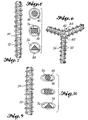
- Figures 7-10 also illustrate the fact that the strands 32 of elastomer material may have any one of various cross sections, such as the cylindrical, polygonal, and triangular cross sections illustrated in Figures 8 and 10.
- ends 42 ( Figure 6) of the coils disposed adjacent the junctures 44 among three or more mutually adjacent strands 32, are interconnected with one another across the junctures, as seen in Figures 1,3 and 6, See Figure 6 in particular, wherein the ends 42 of the coils are intertwined with one another to tether each of them to the juncture 44.
- the strands in the network of Figures 1-3 are crisscrossed with one another in a pattern comprised of X-shaped sub-patterns 46 which are arrayed in tandem with one another along the lengthwise dimension of the posterior portion, to correspond with the direction of translatory motion of the shoe when walking on a surface thereopposite.
- the sub-patterns Given the exoskeleton of coils around the respective strands of the sub-patterns, the sub-patterns form traction pads on the face of the sole to aid in the translatory motion of the shoe on the surface.
- the fingers 48 at the outlying ends of the strands midway the sides of the pattern are interconnected with one another in V-shaped formations, to interconnect the pads with the sides of the loop 28, and the fingers 50 at the opposing end portions of the pattern are I-shaped only, to interconnect the remaining strands of the pads with the respective end portions of the loop 28 thereadjacent.
- the respective fingers 48 and 50 wrap about the periphery 18 of the sole and grip the same as the sock takes on the form of a muzzle for the sole. As such, the fingers serve as the rim portion of the sock.
- the muzzle-forming version seen in Figures 1-3 is operative for the purposes of my invention, but has several drawbacks which are eliminated by the other versions of it to be described shortly.
- the loop 28 is preferably monolithic. rather than in several sections joined at welds therebetween, as seen at 52 in Figure 1.
- the loop 28 is preferably circular, rather than oblong with V-shaped fore and aft portions, as seen in Figure 1. In this way, the loop will be prone to relax more evenly about the welt under the hoop tension therein, when the sock is sleeved about a sole.
- the pattern of the network is preferably devoid of any additional strand, such as that seen at 54 in Figure 1, running lengthwise the pattern of the network and interconnecting it with the toe and heel of the loop.
- This additional strand 54 has a tendency to restrict the stretchability of the sock transverse the axis 24 thereof, when the sock is sleeved about the sole in the mounting of it on the sole.
- the ends of the coils remote from the sub-patterns, that is. those approaching the fingers of the sock are terminated short of the fingers, rather than wound about the fingers and connected with the loop.
- the coils are also interconnected with the junctures in a manner to enable them to range more freely from the junctures, in the accordion-like movement of the turns therewithin, even though they remain tethered to the junctures, as shall be explained more fully hereinafter.
- the coils in each V-shaped formation of the respective sub-patterns are preferably wound in opposite helical directions from one another about the strands thereof, in the directions relatively toward the junctures of the sub-patterns, as shall also be explained more fully hereinafter.
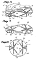
- Figures 4 and 5 illustrate a technique by which the sock may be sleeved about the sole 4 of a shoe, much as a rubber is mounted on a shoe.
- the angularly successive section of the loop 28 at the toe of the sock is gripped in one hand and hooked about the angularly successive section of the toe of the welt 2, so as to engage the section of the loop with the adjacent portion of the axially upwardly oriented annular surface 16 on the welt.
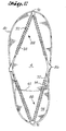
- Figure 11 shows a cowling 60 from which one of the more preferred muzzle-forming socks of my invention can be formed for sleeving about the sole of a shoe.
- the loop 62 is circular, monolithic, and encompasses a network in which the strands 32 are interconnected with one another to form star-shaped sub-patterns 64 that can be arrayed in tandem with one another lengthwise the sole of the shoe.
- the strands 32 making up the sidewise V-shaped formations 66 of the sub-patterns are interconnected with the loop 62, moreover, by pairs of V-shaped fingers 68 at those ends of the formations remote from the junctures 70 of the sub-patterns; whereas the V-shaped formations 72 of the sub-patterns at the toe and heel of the sock are interconnected with the loop by I-shaped fingers 74 at those ends of the formations remote from the junctures.
- the toe and heel of the sock engage the outer periphery 18 of the sole at either side of the toe and heel thereof, whereas the sides of the sock have more heavily reinforced fingers 68 thereon to counter any side slippage in the sock at the footprint of engagement between the sole and the walking surface therebelow.
- the coils 34 wound about the sub-patterns 64 are tethered only to the junctures 70 thereof, and as seen in Figure 14, are formed in each V-shaped formation by a single coil 76 having the respective end portions thereof loosely helically wound about the respective strands 32 in the formation, as represented by the arrows 78, and an oblique connection 40 ( Figures 8 and 10) therein intermediate the mutually adjacent endmost turns in the respective end portions of the coil, wound about the adjacent juncture 70 to tether the end portions to the network.
- the ends of the coil remote from the juncture 70 terminate short of the ends of the strands corresponding thereto in the formation, so that the fingers 68 and 74 therebeyond are uncoiled as they wrap about the outer periphery of the sole to form the rim portion of the sock.
- the endmost portions of the coil in each V-shaped formation are wound in opposite helical directions about the pair of strands, in the directions relatively toward the juncture 70 at the apex of the respective formation. In this way, any lateral and/or endwise displacement forces, i.e., side slippage, arising in the area of the footprint between the sole and the surface therebelow, are effectively neutralized as the forces confront the oppositely wound turns of the formations.
- Figures 15 - 17 illustrate another departure from Figures 1-3.
- the loop 80 has an effective diameter approximating that of the periphery of the posterior portion 82 of the sock 84, so that the loop 80 effectively registers with the periphery of the posterior portion, and the fingers 86 upstand between the two, to form a somewhat slipper-shaped sock, even when the sock is in the relatively limp unactivated cowling stage of its existence.
- the network of strands 32 is also in the form of a diamond-shaped pattern, the mutually opposing V-shaped formation 88 of which have their apices at the toe and heal of the sock, and the coils 34 in the exoskeleton of which are tethered only to the junctures 90 at those apices.
- the sock 84 is more stretchable in the lengthwise direction thereof, to enable it to be mounted on soles 4 of differing lengths.
- the sock 84 in Figures 15-17 also takes into account the fact that the instep 92 formed by the raised heel 94 of a shoe, provides a recess in which the network of strands 32 is somewhat protected from the abrasive action of the footprint, even when the coils 34 are retracted from the midsection of the sock, as shown in Figure 17.
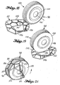
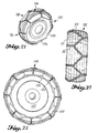
- Figures 18-23 show a coil equipped girdle-forming version of my device, and a sequence of steps by which the sock 96 of the device can be sleeved about the outer periphery or tire 98 of a ground engaging wheel 100, even while the wheel remains in engagement with the ground.
- the wheel comprises a "wheel-shaped" boss driven at its hub or “carrier” 130 (Figure 18) for rotation about an axis 132 ( Figure 18).
- the sock 96 comprises a loop 102, a rim portion 104, and a posterior portion 106, but in this instance, the rim portion 104 ( Figure 21) comprises the network 134 ( Figure 18) of strands 32 and has an exoskeleton of coils 34 supported thereon, whereas the posterior portion 106 of the sock is circumposed about the axis of the sock at the operatively rearward end thereof, adjacent the rim portion 104 of the sock.
- the sock 96 forms an open ended girdle for augmenting the traction between the tire and a ground surface (not marked as such) therebelow, at the footprint of engagement between the two.
- the posterior portion 106 of the sock takes the form of a second continuously uninterrupted outside loop of the elastomer material, and this outside loop 106 engages the face, i.e., the axially outwardly oriented sidewall 108 of the tire of the wheel, in an annulus substantially opposed to the first mentioned inside loop 102 of the sock, so that the sock 96 is generally circumferentially balanced about the operatively forward and rearward ends thereof when the sock is sleeved about the wheel with the inside and outside loops 102 and 106 thereof engaged with the axially inwardly oriented sidewall 110 ( Figure 32) of the tire, and the axially outwardly oriented sidewall 108 of the tire, respectively, in the partially relaxed condition of the sock.
- the first step is to form the cowling 112 of the sock into a pile on the ground in which the bottoms of the loops 102 and 106 are disposed at the bottom of the pile, and the bottom of the inside loop 102 is disposed so that it will be at the inside of the tire 98 when the tire is driven over the pile, as in Figure 19, to make a footprint of engagement between the tire and the surface at a point within the pile.
- the bottom of the outside loop 106 is laid outside of the footprint, and the remainder of the outside loop and the rim portion 104 are folded relatively away from the site of the bottom of the inside loop 102 and in the direction of the site of the bottom of the outside loop 106, so that the remainder lies crosswise the footprint, but outside of the footprint itself in the direction of travel of the wheel. See Figure 19 once again.
- FIG. 24 Several patterns are preferred for the network of strands 32 in the rim portion 104 of the sock.
- those seen in Figures 24 - 26 provide other options in which the V-shaped formations 116 of the respective sub-patterns of the network, have coils 34 thereon made up from a single coil 76 ( Figure 14), the end portions of which provide the coils for the respective strands of the sub-patterns, and an intermediate oblique connection 40 ( Figures 8 and 10) of which provides a tether for the end portions at the apex or juncture 118 of each formation.
- the apices 118 of the respective V-shaped formations point in a direction crosswise the axis 120 of the sock and circumferentially thereof.
- they point in a direction parallel to the axis.
- they point again crosswise of the axis, but at oblique angles thereto, first in one direction of the axis and then in the other, and in Y-shaped sub-patterns, rather than the X-shaped sub-patterns of Figures 23 and 24.
Landscapes
- Engineering & Computer Science (AREA)
- Mechanical Engineering (AREA)
- Orthopedics, Nursing, And Contraception (AREA)
- Footwear And Its Accessory, Manufacturing Method And Apparatuses (AREA)
- Professional, Industrial, Or Sporting Protective Garments (AREA)
- Organic Low-Molecular-Weight Compounds And Preparation Thereof (AREA)
- Pulleys (AREA)
- Lubricants (AREA)
- Friction Gearing (AREA)
- Manufacture Of Iron (AREA)
- Devices For Conveying Motion By Means Of Endless Flexible Members (AREA)
Claims (17)
- Dispositif d'augmentation de la traction destiné à être installé autour d'une bosse mobile en forme de plaque ou en forme de roue pour augmenter la traction dans l'empreinte d'engagement entre la bosse et une surface interactive opposée à celle-ci lorsque la surface interactive entraíne ou est entraínée par la bosse dans le mouvement de celle-ci, la bosse étant fonctionnellement posée tout autour relativement radialement vers l'extérieur autour d'un axe (8, 132) d'un support (10, 130) sur lequel la bosse est fonctionnellement supportée, et reliée à une extrémité du support (10, 130) de manière à avoir des côtés orientés relativement axialement vers l'intérieur et axialement vers l'extérieur sur celle-ci, relativement au support, et la bosse présentant une portion qui s'étend transversalement sur l'extrémité du support de manière à avoir une face (14, 108) sur son côté orienté axialement vers l'extérieur, une portion de bride périphérique extérieure (2) ayant un côté orienté axialement vers l'intérieur (16, 110) ainsi qu'une périphérie extérieure (18, 98) qui est interposée entre la surface annulaire orientée axialement vers l'intérieur (16, 110) de la portion de bride (2) et la face (14, 108) de la bosse,
le dispositif d'augmentation de la traction comprenant:caractérisé par la combinaison de:un recouvrement (20, 60, 112) en matériau élastique flexible qui, lorsqu'il est activé pour l'installation sur la bosse, peut être réalisé en une chaussette élastique (22, 84, 96) pour une prise à ajustement serré autour de la bosse à sa périphérie externe (18, 98),la chaussette (22, 84, 96) ayant un axe (24, 120) pour un alignement général avec l'axe (8, 132) du support, des extrémités fonctionnellement avant et arrière qui sont espacées l'une de l'autre le long de l'axe (24, 120) de la chaussette, une portion de bord annulaire (26, 104) en matériau élastique flexible qui est posé tout autour de l'axe (24, 120) de la chaussette (20, 84, 96) pour une mise en prise avec la périphérie externe (18, 98) de la bosse, une boucle continuellement ininterrompue (28, 62, 80, 102) en matériau élastique flexible qui est posé autour de l'axe (24, 120) de la chaussette à son extrémité fonctionnellement avant pour une mise en prise avec la surface annulaire orientée axialement vers l'intérieur (16, 110) de la portion de bride (2) et une portion postérieure (30, 82, 106) en matériau élastique flexible qui est posée tout autour de l'axe (24, 120) de la chaussette (20, 84, 96) à son extrémité fonctionnellement arrière pour une mise en prise avec la face (18, 108) de la bosse,la boucle (28, 62, 80, 102) définissant une ouverture d'extrémité à travers laquelle la chaussette (22, 84, 96) peut être enfilée autour de la bosse autour de sa périphérie externe (18, 98), mais lorsqu'elle est à l'état normalement relâché, la boucle (28, 62, 80, 102) et la portion postérieure (30, 82, 106) de la chaussette (22, 84, 96) ont un diamètre à leur portion de bord (26, 104) qui est tellement plus petit que la périphérie extérieure (18, 98) de la bosse que la chaussette (22, 84, 96) peut seulement être enfilée autour de la périphérie externe (18, 98) de la bosse en étirant temporairement la boucle (28, 62, 80, 102), le bord (26, 104) et les portions postérieures (30, 82, 106) de la chaussette (22, 84, 96) dans des directions transversales à l'axe de celle-ci, lorsqu'on fait passer la chaussette (22, 84, 96) axialement vers l'intérieur autour de la bosse et qu'on la relâche ensuite pour s'engager étroitement autour de la bosse à sa périphérie externe (18, 98) lorsque la tension périphérique dans la boucle (28, 62, 80, 102), le bord (26, 104) et les portions postérieures (30, 82, 106) de la chaussette (22, 84, 96) amène la chaussette (22, 84, 96) à reprendre un état partiellement relâché sur la bosse,la portion de bord (104) de la chaussette (96), dans le cas d'une bosse en forme de roue, ou la portion postérieure (30, 82) de la chaussette (22, 84), dans le cas d'une bosse en forme de plaque, ayant des côtés périphériques relativement intérieur et extérieur sur celle-ci pour s'opposer à la bosse et à la surface interactive, respectivement, dans l'empreinte d'engagement entre celles-ci, et comprenant plusieurs torons oblongs (32) en matériau élastique flexible qui ont des portions d'extrémité disposées de manière opposée et qui sont interconnectées entre elles à des jonctions (44, 70, 90) entre des portions d'extrémité adjacentes de torons adjacents (32) pour former un réseau (46, 64, 88, 134) de matériau qui est positionné entre les côtés de la portion précitée pour donner de l'élasticité à la portion précitée sur une zone de celle-ci correspondant à l'empreinte d'engagement entre la bosse et la surface interactive,le réseau (46, 64, 88, 134) présentant un exo-squelette d'éléments oblongs (34) générateurs de traction, en forme de bobine, enfilés autour desdits torons (32) en matériau élastiquement flexible pour former une galerie de cavités de protection oblongue (36) pour les torons à l'intérieur,les éléments générateurs de traction respectifs (34) sont généralement co-extensifs avec les torons respectifs (32) correspondant à ceux-ci dans la zone d'une portion correspondant à l'empreinte d'engagement, et comportant des portions d'extrémité opposées sur les côtés périphériques interne et externe respectifs de la portion précitée de la chaussette (22, 84, 96) pour former une carapace autour du réseau (46, 64, 88, 134) contre une action abrasive de l'empreinte à la fois de la bosse et de la surface interactive opposée à celle-ci, etchacun des éléments générateurs de traction respectifs (34) étant élastiquement flexible et ayant une portion d'extrémité reliée au réseau (46, 64, 88, 134) à une jonction adjacente (44, 70, 90) à l'intérieur,les éléments générateurs de traction (34) étant aussi lâchement en prise autour des torons respectifs (32) en matériau élastiquement flexible correspondant à ceux-ci que le réseau (46, 64, 88, 134) peut flêchir élastiquement dans le exo-squelette pendant l'étape d'enfilage de la chaussette (22, 84, 96) autour de la bosse, et pendant tout mouvement ultérieur de la chaussette (22, 84, 96) relativement à la bosse et à la surface interractive à l'empreinte d'engagement entre celles-ci. - Dispositif d'augmentation de traction selon la revendication 1, caractérisé en outre en ce que le exo-squelette est compressible élastiquement transversalement aux côtés périphériques interne et externe de la portion précitée de la chaussette (22, 84, 96) pour absorber toutes les forces de compression agissant entre la bosse et la surface interactive transversales à l'empreinte d'engagement entre celles-ci, mais le exo-sqelette est également suffisamment résistant à des forces pour que le réseau de torons (32) reste sensiblement lâchement enfilé dans les éléments générateurs de traction (34) correspondant à ceux-ci pour flêchir dans le sens de la longueur et transversalement aux axes longitudinaux de ceux-ci lorsque la portion précitée de la chaussette (22, 84, 96) fléchit dans la zone du réseau (46, 64, 88, 134) et que le exo-squelette ne peut pas fléchir en réponse à cela.
- Dispositif d'augmentation de traction selon la revendication 1, caractérisé en outre en ce que l'exo-squelette comprend une multiplicité de bobines oblongues élastiquement flexibles (38) en un matériau de traction dur et durable qui sont lâchement enroulés hélicoïdalement autour de torons (32) du réseau (46, 64, 88, 134) de telle sorte que les axes longitudinaux des bobines (38) coïncident sensiblement avec les axes longitudinaux des torons (32).
- Dispositif d'augmentation de traction selon la revendication 3, caractérisé en outre en ce que trois torons mutuellement adjacents ou plus (32) sont interconnectés entre eux pour former une jonction (44, 70, 90) parmi ceux-ci, une paire de torons mutuellement adjacents (32) ayant des bobines (38) enroulées lâchement hélicoïdalement autour de ceux-ci, et les extrémités des bobines (38) disposées d'une manière adjacente à la jonction (44, 70, 90) étant interconnectées entre elles à la jonction (44, 70, 90) pour attacher les bobines (38) au réseau (46, 64, 88, 134).
- Dispositif d'augmentation de traction selon la revendication 4, où l'élément de traction (34) présente des extrémités éloignées de la jonction (44, 70, 90), se terminant peu avant les extrémités du toron (32) reçu dans celui-ci.
- Dispositif d'augmentation de traction selon la revendication 4, caractérisé en outre en ce que les bobines (38) sont enroulées dans des directions hélicoïdales opposées autour d'une paire de torons mutuellement adjacents (32), dans les directions le long de leurs axes longitudinaux respectifs relativement vers la jonction (44, 70, 90).
- Dispositif d'augmentation de traction selon la revendication 4, caractérisé en outre en ce que trois torons ou plus (32) sont interconnectés selon des formations en V, avec leurs sommets à la jonction (44, 70, 90) de celles-ci.
- Dispositif d'augmentation de traction selon la revendication 7, caractérisé en outre en ce que les formations en V sont disposées les unes en face des autres avec un seul sommet entre celles-ci pour former un sous-motif en forme de X de torons (32) ayant des bobines oblongues (38) enroulées lâchement hélicoïdalement autour de ceux-ci pour former un coussinet de traction dans le réseau (46, 64, 88, 134) aux côtés périphériques interne et externe de la portion précitée de la chaussette (22, 84, 96).
- Dispositif d'augmentation de traction selon la revendication 7, caractérisé en outre en ce que de multiples formations en V sont orientées symétriquement d'une manière angulaire autour d'un seul sommet de celles-ci pour former un sous-motif de torons en forme d'étoile (32) ayant des bobines oblongues (38) enroulées lâchement hélicoïdalement autour de ceux-ci pour former un coussinet de traction dans le réseau (46, 64, 88, 134) aux côtés périphériques interne et externe de la portion précitée de la chaussette (22, 84, 96).
- Dispositif d'augmentation de traction selon la revendication 3, caractérisé en outre par quatre torons (32) interconnectés les uns avec les autres selon des formations en V qui sont disposées d'une manière opposée les unes aux autres, les extrémités des torons respectifs (32) dans celles-ci étant éloignées des sommets respectifs de celles-ci, interconnectées les unes avec les autres pour former un sous-motif en forme losange de torons (32) ayant des bobines oblongues (38) enroulées lâchement hélicoïdalement autour de ceux-ci, pour former un coussinet de traction dans le réseau (46, 64, 88, 134) aux côtés périphériques interne et externe de la portion précitée de la chaussette (22, 84, 96).
- Dispositif d'augmentation de traction selon la revendication 1, caractérisé en outre, dans le cas où la bosse est une bosse en forme de plaque, dont la face est fonctionnellement en prise avec une surface interactive opposée à celle-ci pour entraíner ou être entraínée par la surface interactive lors du mouvement de la bosse, en ce que la portion postérieure (30, 82) de la chaussette (22, 84) est positionnée sur l'extrémité fonctionnellement arrière de la chaussette (22, 84), comprend le réseau (46, 64, 88) de torons (32) et comporte un exo-squelette d'éléments générateurs de traction (34) supportés sur celui-ci de telle sorte que lorsque la chaussette (22, 84) est enfilée autour de la bosse, la chaussette (22, 84) forme un museau autour de la bosse pour augmenter la traction entre la face (18) de la bosse et une surface interactive opposée à celle-ci, à l'empreinte d'engagement entre celles-ci.
- Dispositif d'augmentation de traction selon la revendication 11, caractérisé en outre, en ce que dans le cas où la bosse est une bosse en forme de plaque, la portion de bord (26) de la chaussette (22, 84) comprend une série de doigts élastiquement flexibles (68, 86) qui sont espacés généralement d'une manière symétrique angulairement autour de l'axe de la chaussette (22, 84) pour interconnecter le réseau (46, 64, 88) de torons (32) à la boucle (28, 62, 80) et pour s'engager autour de la périphérie externe (18) de la bosse lorsque la chaussette (22, 84) est enfilée autour de celle-ci, de telle sorte que la boucle (28, 62, 80) et la portion postérieure (30, 82) de la chaussette (22, 84) viennent en prise avec la surface annulaire orientée axialement vers l'intérieur de la portion de bride (2) et la face de la chaussette (22, 84) respectivement, à l'état partiellement relâché de la chaussette (22, 84).
- Dispositif d'augmentation de traction selon la revendication 1, caractérisé en outre, dans le cas où la bosse est une bosse en forme de roue, que la périphérie externe (98) de celle-ci est fonctionnellement mise en prise avec une surface interactive opposée à celle-ci pour entraíner ou être entraínée par la surface interactive dans le mouvement de la bosse, en ce que la portion de bord (104) de la chaussette (96) comprend le réseau (134) de torons (32) et comporte un exo-squelette des éléments générateurs de traction (34) supportés sur celui-ci, et la portion postérieure (106) de la chaussette (96) est posée autour de l'axe de la chaussette (96) à son extrémité fonctionnellement arrière adjacente à la portion de bord (104) de la chaussette (96) de telle sorte que lorsque la chaussette (96) est enfilée autour de la bosse, la chaussette (96) forme une ceinture à extrémité ouverte autour de la bosse pour augmenter la traction entre la périphérie (98) de la bosse et une surface interactive opposée à celle-ci, à l'empreinte d'engagement entre celles-ci.
- Dispositif d'augmentation de traction selon la revendication 13, caractérisé en outre en ce que la portion postérieure (106) de la chaussette (96) prend la forme d'une seconde boucle continuellement ininterrompue (106) en matériau élastiquement flexible qui vient en prise avec la face de la bosse selon un anneau opposé sensiblement axialement à la première boucle mentionnée (102) de la chaussette (96) de sorte que la chaussette (96) est généralement circonférentiellement équilibrée autour de ses extrémités relativement avant et arrière lorsque la chaussette (96) est enfilée autour de la bosse et que les première et seconde boucles mentionnées (102, 106) de celles-ci sont en prise avec la surface annulaire orientée axialement vers l'intérieur de la portion de bride et la face de la bosse, respectivement, à l'état partiellement détendu de la chaussette.
- Dispositif d'augmentation de traction selon la revendication 1, caractérisé en outre en ce que dans le cas où la bosse est une bosse en forme de plaque, la bosse est allongée transversalement dans sa direction de mouvement, et les torons (32) dans le réseau (46, 64, 88) sont interconnectés les uns aux autres selon des formations en V ayant des sommets aux jonctions (44, 70, 90) entre celles-ci, et les formations sont orientées dans le réseau (46, 64, 88) de telle sorte que leurs sommets pointent dans une direction parallèle à la direction en longueur de la bosse lorsque la chaussette (22, 84, 96) est enfilée autour de celle-ci.
- Dispositif d'augmentation de traction selon la revendication 1, caractérisé en outre en ce que dans le cas où la bosse est une bosse en forme de roue, les torons (32) dans le réseau sont interconnectés les uns aux autres selon des formations en V avec des sommets aux jonctions entre celles-ci, et les formations sont orientées dans le réseau (134) de telle sorte que leurs sommets pointent dans une direction transversale à l'axe (132) du support (130) et circonférentiellement de la bosse.
- Dispositif d'augmentation de traction selon la revendication 1, caractérisé en outre en ce que dans le cas où la bosse est une bosse en forme de roue, les torons (32) du réseau (134) sont interconnectés entre eux selon des formations en V avec des sommets à leurs jonctions, et les formations sont orientées dans le réseau de telle sorte que leurs sommets pointent dans une direction parallèle à l'axe (132) du support (130) lorsque la chaussette (96) est enfilée autour de la bosse.
Applications Claiming Priority (3)
| Application Number | Priority Date | Filing Date | Title |
|---|---|---|---|
| US231095P | 1995-08-14 | 1995-08-14 | |
| US602310 | 1995-08-14 | ||
| PCT/US1996/013107 WO1997006707A1 (fr) | 1995-08-14 | 1996-08-12 | Dispositif d'augmentation de la traction |
Publications (3)
| Publication Number | Publication Date |
|---|---|
| EP0902628A4 EP0902628A4 (fr) | 1999-03-24 |
| EP0902628A1 EP0902628A1 (fr) | 1999-03-24 |
| EP0902628B1 true EP0902628B1 (fr) | 2005-01-19 |
Family
ID=21700187
Family Applications (1)
| Application Number | Title | Priority Date | Filing Date |
|---|---|---|---|
| EP96930515A Expired - Lifetime EP0902628B1 (fr) | 1995-08-14 | 1996-08-12 | Dispositif d'augmentation de la traction |
Country Status (7)
| Country | Link |
|---|---|
| US (1) | US5909945A (fr) |
| EP (1) | EP0902628B1 (fr) |
| AT (1) | ATE287224T1 (fr) |
| DE (1) | DE69634210T2 (fr) |
| DK (1) | DK0902628T3 (fr) |
| ES (1) | ES2236749T3 (fr) |
| WO (1) | WO1997006707A1 (fr) |
Families Citing this family (27)
| Publication number | Priority date | Publication date | Assignee | Title |
|---|---|---|---|---|
| US6810606B1 (en) * | 1988-07-15 | 2004-11-02 | Anatomic Research, Inc. | Shoe sole structures incorporating a contoured side |
| DE20304647U1 (de) * | 2003-03-21 | 2003-05-22 | Ottinger, Regina, 78224 Singen | Gleitschutzvorrichtung zum Aufziehen auf einen Schuh |
| DE202005021967U1 (de) * | 2004-02-18 | 2011-11-09 | Sure Foot Corp. | Rutschfester Überschuh |
| US20050269878A1 (en) * | 2004-03-19 | 2005-12-08 | James Lefgren | Carbide studs for stability and motive traction |
| US20100293818A1 (en) * | 2004-03-19 | 2010-11-25 | James Lefgren | Carbide Studs for Stability and Motive Traction of Footwear |
| US20060096130A1 (en) * | 2004-11-09 | 2006-05-11 | May Frederick R | Slip resistant ski boot protection apparatus |
| US20090307931A1 (en) * | 2008-06-17 | 2009-12-17 | Frederick Robert May | Slip resistant ski boot protection apparatus |
| US20120266491A1 (en) * | 2004-11-09 | 2012-10-25 | Frederick Robert May | Slip resistant ski boot protection apparatus |
| KR200381767Y1 (ko) * | 2005-01-19 | 2005-04-18 | 최진홍 | 스파이크가 설치된 체인형 아이젠 |
| USD599986S1 (en) | 2006-02-16 | 2009-09-15 | The Original Australian, Llc | Shoe sole |
| WO2009097642A1 (fr) * | 2008-02-07 | 2009-08-13 | Davidda Pty Ltd | Chaussette |
| WO2010016854A1 (fr) * | 2008-08-07 | 2010-02-11 | Kako International, Inc. | Dispositif de traction personnel |
| US8256140B2 (en) | 2009-01-21 | 2012-09-04 | Kako International Inc. | Personal traction device |
| FR2952279B1 (fr) * | 2009-11-06 | 2011-11-25 | Joubert Productions | Chausson antiderapant |
| USD655903S1 (en) * | 2010-02-11 | 2012-03-20 | Hillsound Equipment Inc. | Crampons |
| USD755493S1 (en) * | 2010-07-28 | 2016-05-10 | Grivel S.R.L. | Mountain sport equipment |
| WO2013056440A1 (fr) * | 2011-10-20 | 2013-04-25 | Esd Technology Consulting & Licensing Co., Ltd | Ensemble chaussure à décharge électrostatique et accessoire associé de mise à la terre d'une chaussure à décharge électrostatique |
| USD694503S1 (en) * | 2012-04-23 | 2013-12-03 | Kyoung Su Lee | Crampons |
| US8991069B2 (en) * | 2012-05-18 | 2015-03-31 | Implus Footcare, Llc | Traction device for footwear |
| GB2513601A (en) * | 2013-04-30 | 2014-11-05 | Steven Alexander Pearce | Traction augmentation devices for shoes, hoofs and wheels |
| US9872537B2 (en) * | 2014-04-08 | 2018-01-23 | Nike, Inc. | Components for articles of footwear including lightweight, selectively supported textile components |
| US9861162B2 (en) | 2014-04-08 | 2018-01-09 | Nike, Inc. | Components for articles of footwear including lightweight, selectively supported textile components |
| USD748903S1 (en) * | 2014-11-13 | 2016-02-09 | Jung Hee Lee | Crampon |
| WO2018037378A2 (fr) * | 2016-08-26 | 2018-03-01 | Snowline Co., Ltd. | Crampons dotés de clous |
| CN114983087B (zh) * | 2017-02-14 | 2025-12-30 | 爱鞋仕有限公司 | 生产足矫正鞋垫的方法、系统以及矫正鞋垫或鞋内底 |
| US10271609B2 (en) * | 2017-04-04 | 2019-04-30 | Step In LLC | Step-on shoe cover and method of use thereof |
| CH720399B1 (de) * | 2022-12-23 | 2025-12-15 | X Tech Swiss Gmbh | Schuh |
Family Cites Families (14)
| Publication number | Priority date | Publication date | Assignee | Title |
|---|---|---|---|---|
| US1350484A (en) * | 1917-05-26 | 1920-08-24 | Non Skid Company | Antiskidding device for tires |
| US1932576A (en) * | 1932-04-18 | 1933-10-31 | Columbian Rope Co | Antiskid device |
| US1982510A (en) * | 1933-07-01 | 1934-11-27 | Jefferson D Frazey | Wader pad |
| US2252027A (en) * | 1940-07-09 | 1941-08-12 | Jr Clement Pasquarella | Clamp for nonskid devices |
| CH329245A (it) * | 1954-03-06 | 1958-04-15 | Pesce Ditta Michele | Dispositivo antisdrucciolevole per pneumatici |
| US3431961A (en) * | 1966-06-02 | 1969-03-11 | Rolf Pfoertner | Elastomeric traction link element |
| US3359659A (en) * | 1967-02-24 | 1967-12-26 | Bonova Ets | Detachable antislipping device for shoes |
| DE1912788A1 (de) * | 1969-03-13 | 1970-09-24 | Werner Gerbecks | Rutschsicherheitsnetze mit Spikes an Stelle von Schneeketten |
| US3616552A (en) * | 1969-09-08 | 1971-11-02 | Alvin R Kniffin | Antiskid footwear |
| CA1138315A (fr) * | 1979-06-07 | 1982-12-28 | Hyok S. Lew | Chaine a neige en boucle fermee |
| JP2509197B2 (ja) * | 1986-11-21 | 1996-06-19 | オ−ツタイヤ株式会社 | タイヤ用滑止具およびその製造方法 |
| JPS63215407A (ja) * | 1987-03-03 | 1988-09-07 | Makoto Goto | タイヤ用滑り止め具の滑り止め体及びその製造方法 |
| JP2913073B2 (ja) * | 1991-05-23 | 1999-06-28 | 株式会社アールディメタル | タイヤ周面に当接配置する滑り止めスプリングコイル |
| US5315768A (en) * | 1993-05-17 | 1994-05-31 | Pacheco Durate S | Shoe traction attachment |
-
1996
- 1996-08-12 EP EP96930515A patent/EP0902628B1/fr not_active Expired - Lifetime
- 1996-08-12 ES ES96930515T patent/ES2236749T3/es not_active Expired - Lifetime
- 1996-08-12 WO PCT/US1996/013107 patent/WO1997006707A1/fr not_active Ceased
- 1996-08-12 AT AT96930515T patent/ATE287224T1/de active
- 1996-08-12 DK DK96930515T patent/DK0902628T3/da active
- 1996-08-12 DE DE69634210T patent/DE69634210T2/de not_active Expired - Lifetime
- 1996-08-12 US US09/011,643 patent/US5909945A/en not_active Expired - Lifetime
Also Published As
| Publication number | Publication date |
|---|---|
| DE69634210D1 (de) | 2005-02-24 |
| EP0902628A4 (fr) | 1999-03-24 |
| DE69634210T2 (de) | 2006-01-05 |
| DK0902628T3 (da) | 2005-05-30 |
| ATE287224T1 (de) | 2005-02-15 |
| WO1997006707A1 (fr) | 1997-02-27 |
| US5909945A (en) | 1999-06-08 |
| EP0902628A1 (fr) | 1999-03-24 |
| ES2236749T3 (es) | 2005-07-16 |
Similar Documents
| Publication | Publication Date | Title |
|---|---|---|
| US5909945A (en) | Traction augmentation device | |
| EP1621370B2 (fr) | Dispositif antidérapant textile pour pneumatiques | |
| CA2218203A1 (fr) | Armature de pneu a attaches multiples | |
| CA2386731A1 (fr) | Chenille elastique sans fin | |
| US5961754A (en) | Slider stopper having suction cups | |
| CA2540145C (fr) | Support de sante a double tension | |
| JP2726082B2 (ja) | タイヤ滑り止め装置 | |
| JPH0211407A (ja) | タイヤの滑り止め具に用いられる弾性部材およびその使用方法 | |
| JP3253643U (ja) | スタッド付き布製タイヤチェーン | |
| JPH04843B2 (fr) | ||
| JPH0257411A (ja) | 自動車用タイヤ滑り止めの締結装置 | |
| JPS62194913A (ja) | タイヤの滑止具 | |
| JP3003907U (ja) | 履物に締結する滑り止めバンド | |
| JPH0380642B2 (fr) | ||
| JPH0439765Y2 (fr) | ||
| KR200315444Y1 (ko) | 이륜자동차용 벨트형 미끄럼방지 장치 | |
| JPS63141811A (ja) | タイヤの滑り止め装置 | |
| JPH1095212A (ja) | 複輪用タイヤチェーン | |
| US3006397A (en) | Traction harness | |
| JPH0439766Y2 (fr) | ||
| JPH01122705A (ja) | 偏平ラジアルタイヤ | |
| JPH0615507U (ja) | 靴装着用防滑具 | |
| JPH03125613A (ja) | 非金属製タイヤチェーンおよびその製造方法 | |
| JPH0446964Y2 (fr) | ||
| JP2004299458A (ja) | バンド引き締め具及びタイヤ用滑止具 |
Legal Events
| Date | Code | Title | Description |
|---|---|---|---|
| PUAI | Public reference made under article 153(3) epc to a published international application that has entered the european phase |
Free format text: ORIGINAL CODE: 0009012 |
|
| 17P | Request for examination filed |
Effective date: 19980615 |
|
| A4 | Supplementary search report drawn up and despatched |
Effective date: 19981105 |
|
| AK | Designated contracting states |
Kind code of ref document: A4 Designated state(s): AT BE CH DE DK ES FI FR GB GR IE IT LI LU MC NL PT SE Kind code of ref document: A1 Designated state(s): AT BE CH DE DK ES FI FR GB GR IE IT LI LU MC NL PT SE |
|
| 17Q | First examination report despatched |
Effective date: 20000901 |
|
| GRAP | Despatch of communication of intention to grant a patent |
Free format text: ORIGINAL CODE: EPIDOSNIGR1 |
|
| GRAS | Grant fee paid |
Free format text: ORIGINAL CODE: EPIDOSNIGR3 |
|
| RAP1 | Party data changed (applicant data changed or rights of an application transferred) |
Owner name: YAKTRAX, INC. |
|
| RIN1 | Information on inventor provided before grant (corrected) |
Inventor name: NOY, THOMAS ELLISTON |
|
| GRAA | (expected) grant |
Free format text: ORIGINAL CODE: 0009210 |
|
| AK | Designated contracting states |
Kind code of ref document: B1 Designated state(s): AT BE CH DE DK ES FI FR GB GR IE IT LI LU MC NL PT SE |
|
| REG | Reference to a national code |
Ref country code: GB Ref legal event code: FG4D |
|
| REG | Reference to a national code |
Ref country code: CH Ref legal event code: EP |
|
| REG | Reference to a national code |
Ref country code: IE Ref legal event code: FG4D |
|
| REF | Corresponds to: |
Ref document number: 69634210 Country of ref document: DE Date of ref document: 20050224 Kind code of ref document: P |
|
| PG25 | Lapsed in a contracting state [announced via postgrant information from national office to epo] |
Ref country code: GR Free format text: LAPSE BECAUSE OF FAILURE TO SUBMIT A TRANSLATION OF THE DESCRIPTION OR TO PAY THE FEE WITHIN THE PRESCRIBED TIME-LIMIT Effective date: 20050419 |
|
| REG | Reference to a national code |
Ref country code: SE Ref legal event code: TRGR |
|
| REG | Reference to a national code |
Ref country code: CH Ref legal event code: NV Representative=s name: NOVAGRAAF INTERNATIONAL SA |
|
| REG | Reference to a national code |
Ref country code: DK Ref legal event code: T3 |
|
| REG | Reference to a national code |
Ref country code: ES Ref legal event code: FG2A Ref document number: 2236749 Country of ref document: ES Kind code of ref document: T3 |
|
| PG25 | Lapsed in a contracting state [announced via postgrant information from national office to epo] |
Ref country code: LU Free format text: LAPSE BECAUSE OF NON-PAYMENT OF DUE FEES Effective date: 20050812 Ref country code: IE Free format text: LAPSE BECAUSE OF NON-PAYMENT OF DUE FEES Effective date: 20050812 |
|
| PG25 | Lapsed in a contracting state [announced via postgrant information from national office to epo] |
Ref country code: MC Free format text: LAPSE BECAUSE OF NON-PAYMENT OF DUE FEES Effective date: 20050831 |
|
| PLBE | No opposition filed within time limit |
Free format text: ORIGINAL CODE: 0009261 |
|
| STAA | Information on the status of an ep patent application or granted ep patent |
Free format text: STATUS: NO OPPOSITION FILED WITHIN TIME LIMIT |
|
| ET | Fr: translation filed | ||
| 26N | No opposition filed |
Effective date: 20051020 |
|
| REG | Reference to a national code |
Ref country code: IE Ref legal event code: MM4A |
|
| PG25 | Lapsed in a contracting state [announced via postgrant information from national office to epo] |
Ref country code: PT Free format text: LAPSE BECAUSE OF NON-PAYMENT OF DUE FEES Effective date: 20050619 |
|
| REG | Reference to a national code |
Ref country code: CH Ref legal event code: PFA Owner name: YAKTRAX, INC. Free format text: YAKTRAX, INC.#629 WARREN AVENUE#BREMERTON, WASHINGTON 98337 (US) -TRANSFER TO- YAKTRAX, INC.#629 WARREN AVENUE#BREMERTON, WASHINGTON 98337 (US) |
|
| REG | Reference to a national code |
Ref country code: DE Ref legal event code: R082 Ref document number: 69634210 Country of ref document: DE Representative=s name: WEICKMANN & WEICKMANN PATENTANWAELTE - RECHTSA, DE Ref country code: DE Ref legal event code: R082 Ref document number: 69634210 Country of ref document: DE Representative=s name: PATENTANWAELTE WEICKMANN & WEICKMANN, DE |
|
| REG | Reference to a national code |
Ref country code: FR Ref legal event code: PLFP Year of fee payment: 20 |
|
| PGFP | Annual fee paid to national office [announced via postgrant information from national office to epo] |
Ref country code: NL Payment date: 20150809 Year of fee payment: 20 |
|
| PGFP | Annual fee paid to national office [announced via postgrant information from national office to epo] |
Ref country code: GB Payment date: 20150812 Year of fee payment: 20 Ref country code: DK Payment date: 20150811 Year of fee payment: 20 Ref country code: CH Payment date: 20150811 Year of fee payment: 20 Ref country code: DE Payment date: 20150804 Year of fee payment: 20 Ref country code: FI Payment date: 20150810 Year of fee payment: 20 Ref country code: ES Payment date: 20150713 Year of fee payment: 20 |
|
| PGFP | Annual fee paid to national office [announced via postgrant information from national office to epo] |
Ref country code: AT Payment date: 20150727 Year of fee payment: 20 Ref country code: FR Payment date: 20150629 Year of fee payment: 20 Ref country code: SE Payment date: 20150811 Year of fee payment: 20 |
|
| PGFP | Annual fee paid to national office [announced via postgrant information from national office to epo] |
Ref country code: IT Payment date: 20150827 Year of fee payment: 20 |
|
| PGFP | Annual fee paid to national office [announced via postgrant information from national office to epo] |
Ref country code: BE Payment date: 20150811 Year of fee payment: 20 |
|
| REG | Reference to a national code |
Ref country code: DE Ref legal event code: R071 Ref document number: 69634210 Country of ref document: DE |
|
| REG | Reference to a national code |
Ref country code: CH Ref legal event code: PL Ref country code: DK Ref legal event code: EUP Effective date: 20160812 |
|
| REG | Reference to a national code |
Ref country code: NL Ref legal event code: MK Effective date: 20160811 |
|
| REG | Reference to a national code |
Ref country code: GB Ref legal event code: PE20 Expiry date: 20160811 |
|
| REG | Reference to a national code |
Ref country code: SE Ref legal event code: EUG |
|
| REG | Reference to a national code |
Ref country code: AT Ref legal event code: MK07 Ref document number: 287224 Country of ref document: AT Kind code of ref document: T Effective date: 20160812 |
|
| PG25 | Lapsed in a contracting state [announced via postgrant information from national office to epo] |
Ref country code: GB Free format text: LAPSE BECAUSE OF EXPIRATION OF PROTECTION Effective date: 20160811 |
|
| REG | Reference to a national code |
Ref country code: ES Ref legal event code: FD2A Effective date: 20161125 |
|
| PG25 | Lapsed in a contracting state [announced via postgrant information from national office to epo] |
Ref country code: ES Free format text: LAPSE BECAUSE OF EXPIRATION OF PROTECTION Effective date: 20160813 |