EP0902601A2 - Ecouteur auriculaire - Google Patents
Ecouteur auriculaire Download PDFInfo
- Publication number
- EP0902601A2 EP0902601A2 EP98114378A EP98114378A EP0902601A2 EP 0902601 A2 EP0902601 A2 EP 0902601A2 EP 98114378 A EP98114378 A EP 98114378A EP 98114378 A EP98114378 A EP 98114378A EP 0902601 A2 EP0902601 A2 EP 0902601A2
- Authority
- EP
- European Patent Office
- Prior art keywords
- contacts
- earpiece
- housing
- coil
- highlighting
- Prior art date
- Legal status (The legal status is an assumption and is not a legal conclusion. Google has not performed a legal analysis and makes no representation as to the accuracy of the status listed.)
- Withdrawn
Links
Images

Classifications
-
- H—ELECTRICITY
- H04—ELECTRIC COMMUNICATION TECHNIQUE
- H04R—LOUDSPEAKERS, MICROPHONES, GRAMOPHONE PICK-UPS OR LIKE ACOUSTIC ELECTROMECHANICAL TRANSDUCERS; ELECTRIC HEARING AIDS; PUBLIC ADDRESS SYSTEMS
- H04R11/00—Transducers of moving-armature or moving-core type
- H04R11/06—Telephone receivers
-
- H—ELECTRICITY
- H04—ELECTRIC COMMUNICATION TECHNIQUE
- H04M—TELEPHONIC COMMUNICATION
- H04M1/00—Substation equipment, e.g. for use by subscribers
- H04M1/02—Constructional features of telephone sets
- H04M1/03—Constructional features of telephone transmitters or receivers, e.g. telephone hand-sets
-
- H—ELECTRICITY
- H01—ELECTRIC ELEMENTS
- H01R—ELECTRICALLY-CONDUCTIVE CONNECTIONS; STRUCTURAL ASSOCIATIONS OF A PLURALITY OF MUTUALLY-INSULATED ELECTRICAL CONNECTING ELEMENTS; COUPLING DEVICES; CURRENT COLLECTORS
- H01R13/00—Details of coupling devices of the kinds covered by groups H01R12/70 or H01R24/00 - H01R33/00
- H01R13/02—Contact members
- H01R13/22—Contacts for co-operating by abutting
- H01R13/24—Contacts for co-operating by abutting resilient; resiliently-mounted
Definitions
- the invention relates to an earpiece according to the genus Main claim.
- Earphones have been used for telephone devices, for example known for a long time. It is in the earpiece of the Handset of a telephone device for a hearing capsule acoustic reproduction from the telecommunications network received data.
- the earpiece according to the invention with the features of The main claim has the advantage that the Simply insert the earpiece into the earpiece Handset can be inserted. Another Operation for contacting the earpiece with Mating contacts, preferably a circuit board in the Handset, for example a soldering process is not required. In this way, the assembly of the earpiece greatly simplified into the earpiece of the handset and requires less time and costs.
- the housing is centered arranged preferably circular cylindrical highlighting and that the contacts at least partially around Highlighting are curved. That way is an extreme compact and space-saving design of the earpiece.
- the second bend in each case a highlighted contact area for contacting the Has counter contacts. Contacting the Counter contacts is thus highlighted by the Contact area additionally supported, so that contact loss is avoided.
- FIG. 1 shows a view of a Earphone according to the invention from above
- Figure 2 is a view the earphone according to the invention from below
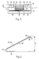
- FIG Cross section through the earpiece according to the invention and
- FIG. 4 a cross section through a resilient contact.
- FIG. 1 denotes an earpiece like this for example, in a corresponding recording Earpiece of a handset of a telephone terminal is housed.
- the earphone 1 includes an im Hollow circular or cylindrical inside Housing 5, which is also a centrally located inside hollow circular or cylindrical highlighting 60 has a smaller radius of the base.
- the Highlighting 60 is from one to the other by highlighting 60 graded surface of the housing 5 and for example by an adhesive connection to this attached insulating body 70 to about one Quarter circle length enclosed.
- About halfway between the The housing 5 has one at both ends of the insulating body 70 starting at the highlight 60, radially to the outer Edge of the magnet 5 extending slot-shaped gap 10 on, which is open at the outer edge of the housing 5.
- two feed lines 95 are arranged, which are separated by one in Figure 1 insulating compound, not shown, from each other are electrically isolated.
- One of the two feed lines 95 is with a contact surface 35 of a first contact 25 connected and the other of the two leads 95 with a contact surface 35 of a second contact 30 connected.
- the two contact surfaces 35 are involved each on one made of printed circuit board material, made of plastic or the like formed insulating surface 40 attached between the highlight 60 and the outer edge of the Housing 5 on the graded by the highlight 60 Surface of the housing 5 on both sides of the gap 10 arranged and for example by an adhesive connection the magnet 5 are connected.
- the insulating surfaces 40 are sufficient each from the edge of the air gap 10 to the beginning of Insulating body 70.
- the two feed lines 95 are used to supply one AC voltage to an inside of the housing 5 according to the figure 3 arranged coil 15 and are accordingly with this Coil 15 connected.
- Inside the housing 5 is on the circular disk-shaped top surface 100 of the highlight 60 cylindrical permanent magnet 105 attached to the Interior of the housing 5 concentric with the circular Diameter of the housing 5 and with a smaller diameter than the highlight 60 protrudes.
- the coil is there at least partially around the permanent magnet 105 wrapped around, not by a in Figure 3 Insulating layer shown from the permanent magnet 105 are electrically isolated.
- the distance between that Permanent magnet 105 and the limit of the housing 5 is chosen so large that a touch of the Permanent magnet 105 wound coil 15 with the Housing limitation is excluded. This can be additional by a likewise not shown in Figure 3, in Inside the boundary of the housing 5 covered Insulation layer can also be ensured.
- For Clarification of the wrapping of the permanent magnet 105 through the coil 15 is for the coil 15 in Figure 3, the a section A-A according to Figure 1, of this Sectional representation has been deviated.
- With metallic Execution of the housing 5 is a non-ferrous metal not used to the magnetic field of the permanent magnet 105 to influence.
- the coil 15 is at the highlight 60 opposite bottom of the housing 5 with a membrane 20th connected.
- the membrane 20 is vibratable in a receptacle 90 on the underside of the housing 5 arranged metal plate 80, as can also be seen in FIG. 3 is, stored, and is used for sound generation by vom Telecommunications network transmitted signals.
- metal plate 80 can also be a plastic or plastic plate otherwise suitable material can be used.
- To the Insulating surfaces 40 facing ends of the insulating body 70 each has the highlight 60 approximately in the middle partially enclosing indentation 75 in Shape of a slit.
- the ring segment has each about the length of a quarter circle.
- the ring segment shaped Indentations 75 of the insulating body 70 serve the purpose Establishing the first and second contacts 25, 30.
- the Insulating body 70 insulates contacts 25, 30 electrically from the metallic housing, if any are the contacting surfaces 35 of the two contacts 25, 30 each connected to a holding part 50, which also bent in a ring and in the respective indentation 75 led almost to the end of the respective indentation 75 is.
- the holding part 50 has a highlighted one Contact surface 65 for contacting mating contacts for example one arranged in the handset PCB on.
- the contact surface 35 is a first resilient bend 45 and the rectilinear in cross section Holding part 50 with a second bend 55 for contacting connected to the counter contacts.
- the second points Bend 55 in each case the highlighted contact surface 65 improved contact with the counter contacts.
- the height H of the contact 25, 30 according to FIG. 4 is greater as the height h of the highlight 60 of the housing 5 according to Figure 3, wherein the contact 25, 30 in Figure 4 is not is drawn to scale. In this way they protrude Contacts 25, 30 in the unactuated state via the Insulating body 70 and the highlighting 60 of the housing 5 out.
- FIG. 2 shows the highlighting 60 of the housing 5 opposite bottom of the earphone 1 shown. It is formed by the metal plate 80, in the four Sound exit holes 85 are attached. The four Sound exit holes 85 are located approximately in the middle region of the metal plate 80, one of the Sound exit holes 85 approximately in the center of the metal plate 80 is arranged. The sound exit holes 85 serve the spread of the sounds produced by the membrane 20.
- FIG. 1 shows a section line A-A shown perpendicular to the gap 10 through the center the earphone 1 runs.
- This Section line A-A shows a cross section through the earpiece 1, see above the representation according to FIG. 3 is obtained.
- FIG. 3 shows recognize that the height of the insulating body 70 is approximately the Height h corresponds to the highlight 60 of the housing 5.
- Figure 3 shows the contacts 25, 30 in the unactuated state.
- the end of contacts 25, 30 with the highlighted Contact surface 65 projects over the insulating body 70 and the highlight 60 of the magnet 5 also.
- Section line A-A runs through the center of the earphone 1, 3 is the centrally located sound exit hole 85 of the metal plate 80 shown, which together with the other sound exit holes 85 the sound exit of the by the tones generated in the receptacle 90 stored membrane 20 enables.
- the earpiece according to the invention can be easily in the intended recording of the earpiece of the Handset of the telephone device are inserted. Then the circuit board with the mating contacts in the handset is inserted, the contacts 25, 30 actuated by the counter contacts and up to the top Boundary surface of the earphone 1 or the highlight 60 and the insulating body 70 is depressed. The pressure force is therefore by the height h of the highlight 60 or the Insulating body 70 defined. The contacts 25, 30 can only up to the upper limit of the insulating body 70 or Highlight 60 to be depressed. The spring force for Contact is made by the first resilient bend 45 causes.
- the magnetic field for exciting the coil 15 can also by other measures familiar to a person skilled in the art, for example realized by an electromagnet or the like become.
Landscapes
- Physics & Mathematics (AREA)
- Engineering & Computer Science (AREA)
- Signal Processing (AREA)
- Electromagnetism (AREA)
- Acoustics & Sound (AREA)
- Headphones And Earphones (AREA)
- Telephone Set Structure (AREA)
Applications Claiming Priority (2)
| Application Number | Priority Date | Filing Date | Title |
|---|---|---|---|
| DE1997139637 DE19739637C1 (de) | 1997-09-10 | 1997-09-10 | Hörkapsel |
| DE19739637 | 1997-09-10 |
Publications (2)
| Publication Number | Publication Date |
|---|---|
| EP0902601A2 true EP0902601A2 (fr) | 1999-03-17 |
| EP0902601A3 EP0902601A3 (fr) | 2006-05-03 |
Family
ID=7841812
Family Applications (1)
| Application Number | Title | Priority Date | Filing Date |
|---|---|---|---|
| EP98114378A Withdrawn EP0902601A3 (fr) | 1997-09-10 | 1998-07-31 | Ecouteur auriculaire |
Country Status (2)
| Country | Link |
|---|---|
| EP (1) | EP0902601A3 (fr) |
| DE (1) | DE19739637C1 (fr) |
Families Citing this family (1)
| Publication number | Priority date | Publication date | Assignee | Title |
|---|---|---|---|---|
| DE10063482B4 (de) * | 2000-12-06 | 2007-03-15 | Phoenix Contact Gmbh & Co. Kg | Elektrische Klemme und Baueinheit aus einem elektronischen Gerät und einer in einem ortsfesten Gehäuse angeordneten elektrischen Klemme |
Family Cites Families (3)
| Publication number | Priority date | Publication date | Assignee | Title |
|---|---|---|---|---|
| US3515168A (en) * | 1968-05-31 | 1970-06-02 | Wayne Manufacturing Co | Street cleaner suction seal |
| US4507800A (en) * | 1982-01-06 | 1985-03-26 | Analog & Digital Systems, Inc. | Enclosed magnet loudspeaker |
| DE3510346A1 (de) * | 1985-03-22 | 1986-10-02 | Fernsprech- und Signalbau KG Schüler & Vershoven, 4300 Essen | Dynamischer, akustischer wandler |
-
1997
- 1997-09-10 DE DE1997139637 patent/DE19739637C1/de not_active Expired - Fee Related
-
1998
- 1998-07-31 EP EP98114378A patent/EP0902601A3/fr not_active Withdrawn
Also Published As
| Publication number | Publication date |
|---|---|
| EP0902601A3 (fr) | 2006-05-03 |
| DE19739637C1 (de) | 1999-02-04 |
Similar Documents
| Publication | Publication Date | Title |
|---|---|---|
| DE69934119T2 (de) | Schall-/ schwingungsgenerator | |
| DE10117860B4 (de) | Vibrationsmotor in Flachbauweise | |
| DE69502505T2 (de) | Elektrodynamischer übertrager | |
| DE60221857T2 (de) | Akustischen Miniwandler | |
| DE102004046959A1 (de) | Oberflächenmontierbarer Linearvibrator | |
| DE10226589A1 (de) | Vibrationsmotor | |
| DE60002649T2 (de) | Lautsprecher für mobile Telefon | |
| DE60025590T2 (de) | Anordnung mit einem elektroakustischen wandler dessen anschlusskontakte sich in der richtung der wandlerachse erstrecken und mit einer gedruckten leiterplatte mit passenden steckkontakten | |
| DE2909477C2 (de) | Anordnung zum Umwandeln akustischer Schwingungen in elektrische Schwingungen und umgekehrt, mit mindestens einem Kondensatorelektretelement, das an eine elektronische Schaltungsanordnung angeschlossen ist | |
| EP4054208A1 (fr) | Appareil auditif, antenne pour un appareil auditif et procédé de fabrication d'un appareil auditif | |
| WO2006027268A1 (fr) | Composant support, dispositif bobine de choc antiparasites et leur procede de production | |
| DE3230060C2 (de) | Piezoelektrischer Summer | |
| DE19739637C1 (de) | Hörkapsel | |
| EP0755165A1 (fr) | Connexion d'un transducteur électro-acoustique à l'intérieur d'un combiné téléphonique | |
| EP0989773A2 (fr) | Dispositif de transducteur du son | |
| DE3736896A1 (de) | Elektroakustischer wandler | |
| AT410742B (de) | Kontaktierung für elektrostatische mikrofonwandler | |
| EP2911312B1 (fr) | Antenne dotée de dispositif de protection et procédé de fabrication | |
| DE60106182T2 (de) | Elektro-akustischer Wandler | |
| AT411558B (de) | Elektroakustischer wandler | |
| DE7804970U1 (de) | Fernsprechhandapparat | |
| DE69815808T2 (de) | Elektroakustischer wandler mit federkontakten mit mindestens einer biegung | |
| EP0609744A1 (fr) | Combiné pour appareil téléphonique à cordon | |
| DE202014000874U1 (de) | Elektronische Baugruppe für ein am Körper zu tragendes Audiogerät | |
| DE19928241B4 (de) | Lautsprecher |
Legal Events
| Date | Code | Title | Description |
|---|---|---|---|
| PUAI | Public reference made under article 153(3) epc to a published international application that has entered the european phase |
Free format text: ORIGINAL CODE: 0009012 |
|
| AK | Designated contracting states |
Kind code of ref document: A2 Designated state(s): AT BE CH CY DE DK ES FI FR GB GR IE IT LI LU MC NL PT SE |
|
| AX | Request for extension of the european patent |
Free format text: AL;LT;LV;MK;RO;SI |
|
| RAP1 | Party data changed (applicant data changed or rights of an application transferred) |
Owner name: SIEMENS AKTIENGESELLSCHAFT |
|
| PUAL | Search report despatched |
Free format text: ORIGINAL CODE: 0009013 |
|
| AK | Designated contracting states |
Kind code of ref document: A3 Designated state(s): AT BE CH CY DE DK ES FI FR GB GR IE IT LI LU MC NL PT SE |
|
| AX | Request for extension of the european patent |
Extension state: AL LT LV MK RO SI |
|
| AKX | Designation fees paid | ||
| STAA | Information on the status of an ep patent application or granted ep patent |
Free format text: STATUS: THE APPLICATION IS DEEMED TO BE WITHDRAWN |
|
| 18D | Application deemed to be withdrawn |
Effective date: 20061104 |
|
| REG | Reference to a national code |
Ref country code: DE Ref legal event code: 8566 |