EP0902518A2 - Energieverteilungssystem in Schiffen - Google Patents
Energieverteilungssystem in Schiffen Download PDFInfo
- Publication number
- EP0902518A2 EP0902518A2 EP98107378A EP98107378A EP0902518A2 EP 0902518 A2 EP0902518 A2 EP 0902518A2 EP 98107378 A EP98107378 A EP 98107378A EP 98107378 A EP98107378 A EP 98107378A EP 0902518 A2 EP0902518 A2 EP 0902518A2
- Authority
- EP
- European Patent Office
- Prior art keywords
- energy
- bus
- power
- ship
- distribution system
- Prior art date
- Legal status (The legal status is an assumption and is not a legal conclusion. Google has not performed a legal analysis and makes no representation as to the accuracy of the status listed.)
- Granted
Links
Images


Classifications
-
- H—ELECTRICITY
- H02—GENERATION; CONVERSION OR DISTRIBUTION OF ELECTRIC POWER
- H02J—ELECTRIC POWER NETWORKS; CIRCUIT ARRANGEMENTS OR SYSTEMS FOR SUPPLYING OR DISTRIBUTING ELECTRIC POWER; SYSTEMS FOR STORING ELECTRIC ENERGY
- H02J4/00—Circuit arrangements for mains or distribution networks not specified as AC or DC; Circuit arrangements for mains or distribution networks combining AC and DC sections or sub-networks
-
- B—PERFORMING OPERATIONS; TRANSPORTING
- B63—SHIPS OR OTHER WATERBORNE VESSELS; RELATED EQUIPMENT
- B63J—AUXILIARIES ON VESSELS
- B63J3/00—Driving of auxiliaries
-
- H—ELECTRICITY
- H02—GENERATION; CONVERSION OR DISTRIBUTION OF ELECTRIC POWER
- H02J—ELECTRIC POWER NETWORKS; CIRCUIT ARRANGEMENTS OR SYSTEMS FOR SUPPLYING OR DISTRIBUTING ELECTRIC POWER; SYSTEMS FOR STORING ELECTRIC ENERGY
- H02J2105/00—Networks for supplying or distributing electric power characterised by their spatial reach or by the load
- H02J2105/30—Networks for supplying or distributing electric power characterised by their spatial reach or by the load the load networks being external to vehicles, i.e. exchanging power with vehicles
- H02J2105/31—Networks for supplying or distributing electric power characterised by their spatial reach or by the load the load networks being external to vehicles, i.e. exchanging power with vehicles for ships or vessels
Definitions
- the invention relates to an energy distribution system in Ships to supply energy to ship zones distributed energy consumers from onboard Energy sources in the preamble of claim 1 defined genus.
- Energy supply e.g. Passenger ships or Navy ships
- Energy supply will have two main switchboards Distribution switches for a redundant energy supply used by important consumer groups.
- This major consumer groups will have two radially designed energy distributions, their associated central control panels in different Ship zones arranged and fed by the energy sources are.
- the invention has for its object an improved Power distribution system in ships of the type mentioned To create a way that is flexible in planning and project planning, easily expandable and suitable for retrofitting Change of power outlets in the individual Ship zones as well as inexpensive to install.
- the task is in an energy distribution system Ships the specified in the preamble of claim 1 Genus according to the invention by the features in Characteristic part of claim 1 solved.
- the power distribution system according to the invention in ships has the advantage that due to the cross-ship zone and continuously through the ship zones or departments installed energy bus the distribution of source energy directly and without the interposition of distribution switches he follows.
- the energy supply to the energy bus takes place via Supply switch directly from the energy sources, namely in those ship zones or departments in which these Energy sources are arranged, the energy dissipation from Power bus takes place in the individual switch Ship zones or departments in which the energy is needed.
- each ship zone or department the energy is transported via power cables to the Consumers or consumer groups and / or via Power cables to subdistribution boards that over Distribution switches and power cables to consumers supply, and / or via sub-buses that instead of or in addition to the sub-distribution panels be used and also via feeder switches Consumers or consumer groups directly through Supply power cables with energy. So that is done overall a decentralized, secure, departmental self-sufficient Supply directly with source energy in the individual Ship zones is always available.
- the inventive concept is suitable for the novel Power distribution system for pre-equipping Ship sectors and is flexible in planning and Project planning as it progresses with the construction progressively growing and within the shipping sectors only standardized individual components are used, so that e.g.
- a second power bus is provided in the same way runs through all ship zones and in the individual Ship zones are provided with outgoing switches.
- the Energy sources are divided between the two energy buses.
- the energy bus or are the energy buses as metal, preferably sheet-encapsulated busbars executed and on the busbars connecting elements for the Outgoing switch provided.
- every power bus receives a higher level of mechanical protection compared to long-distance power cables and a highly effective EMC shielding, which ensures the reliability of the Energy bus is increased considerably.
- At least one of the emergency care of the Energy distribution system serving energy source a so-called Emergency generator
- a so-called Emergency generator by means of an emergency feed switch on the Power bus can be switched on, at the latest when it is switched on the emergency power source not all Emergency service consumers separated from the power bus are.
- the separation takes place via the black-out of the Power distribution network by means of in the outgoers the main and secondary consumers more integrated Undervoltage release.
- the energy bus results in cost savings compared to the conventional installation of two separate power distribution systems for emergency and Main business and in addition a higher and more secure Availability of main and emergency energy in all Departments or zones of the ship.
- By automatic Shutdown of all non-emergency care Energy bus consumers will overload the less powerful emergency power generator avoided.
- the power bus voltage transformers for operating Secondary voltage networks in the individual ship zones connected.
- the energy bus across the ship zones above the Bulkheads relocated the ship zones from each other separate waterproof. This has the advantage that e.g. at flooded departments of the ship's energy distribution of the ship runs in the safe ship area and the Emergency operation can be maintained. The through that penetrating water endangered parts of the energy bus are separated by tabs or switches.
- the ring bus is advantageously used in walk-in, armored boxes laid out as with ships military deployment profile on the two Longitudinal sides of the ship can be found above the bulkheads.
- This ring bus configuration and the extensive Laying in the secure box girder will Power supply in the primary voltage range with high Security, availability and stability guaranteed.
- the required energy supply with Secondary voltage is distributed across the voltage transformers arranged in respective ship zones, the Depending on the application, simple or redundant become.
- a two-stage control and monitoring of the Power bus provided a central remote control and monitoring and decentralized local controls and - surveillance in the individual ship zones.
- the central remote control and monitoring becomes more central Position, e.g. in a power generation station or in a machine control station, installed, and for Transmission of control and monitoring signals a fast data bus, e.g. ASI, used.
- the Local control and monitoring is carried out manually on the Installation location of the switching devices by manual Actuation options on the switching devices and by visual monitoring of the switching device with corresponding means, such as switch position indicators, Indicator lights, measuring instruments and the like, at the installation site of the Switching device.
- the decentralized on-site control and monitoring provides the relapse function for the central Remote control and monitoring.
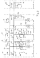
- FIG. 1 The one shown in Figure 1 in the block diagram Power distribution system in a ship is used for Energy supply from energy consumers 10 out on-board energy sources 11, 12, here from generators G are represented, but also transformers or Can be a converter.
- the total of energy consumers 10 is in different ways on several ship zones 15 distributed to 19, which also ship departments or Ship sectors are called. Are in the embodiment four different with energy consumers 10 equipped ship zones 15 to 19 shown. Your However, the number is arbitrary and depends on the size of the ship and the needs of the division into Energy supply zones.
- the main component of the energy distribution system is a from the energy sources 11, 12 powered energy bus 20, the is installed across all shipping zones, i.e. all Ship zones 15 to 19 runs through.
- the two Energy sources 11, 12 are each via a feed switch 22 coupled to the power bus 20, directly in the ship zone 16 in which they are arranged.
- Out spatial reasons takes place in the embodiment of Fig.1 the coupling of the energy sources 11, 12 to the energy bus 20 not directly, but via a bus branch 23, the is inseparably connected to the power bus 20.
- the Energy consumption from the energy bus 20 takes place in the individual Ship zones 15 to 19 for those available there Energy consumer 10 by means of outgoing switch 25, the the one that runs through the respective ship zones 15 to 19 Sections of the power bus 20 are connected.
- the outgoing switches 25 are on the output side via load cables 26 either directly with a consumer 10 (ship zones 15, 16) or via a load cable 26 with a Sub-distribution board 27 connected (ship zone 17).
- the sub-distribution panel 27 in turn has one Row of distribution switches 28 on the output side via load cable 26 with one consumer 10 each are connected (ship zone 17).
- Sub-distribution panel 27 can also be a sub-power bus 29 be laid in the ship zone, as shown in Fig.1 for the ship zone 18 is shown. At this The lower energy bus 29 is then the consumer 10 in the Ship zone 18 via load cable 26 and outgoing switch 25 connected.
- Ship zones 17 and 18 additional outgoing switch 30 connected to the power bus 20, through which the Energy supply in an emergency.
- the consumer 10 is connected to two load cables 26 and two outgoing switches 25 are placed on the power bus 20, like this for a consumer 10 in ship zone 17 and is shown in ship zone 19.
- the power bus 20 - and also the bus branch 23 - by means of a metal encapsulated, e.g. sheet encapsulated track realized as it is commercially available.
- This metal encapsulated track carries a variety of Connection elements for connecting the outgoing switch 25 in the individual ship zones 15 to 19.
- the shown in Figure 2 in the block diagram Power distribution system offers through a second Power bus 21 a redundant power supply for the Ship zones 15 to 19.
- the second energy bus 21 is identical to the energy bus 20 described above trained and also across ship zones installed throughout.
- Existing energy sources 11 to 14, in the embodiment of Figure 2 again Generators G symbolize are on the two Power buses 20, 21 split, with a split into an equal ratio is preferred.
- the Energy sources 11 to 14 can have one each Feed switch 22 directly to the power bus 20 and Energy bus 21 be coupled, but also - like this one in 2 is shown - via the feed switch 22 Bus branches 23, 24 are connected by the Power bus 20 or 21 in ship zones 16 and 18 branch off.
- the two energy buses 20, 21 run parallel, for example one on the starboard side and the other port side, by the appropriate Ship zones 15 to 19.
- the two energy buses 20, 21 are at any point with one another Coupling switch 31 connected so that if the Energy supply for an energy bus 20 or 21 the Power supply via the other power bus 21 or 20 can be effected.
- a redundant Power supply for particularly important electricity consumers 10 in each of these ship zones 16 to 19 two load cables 26, each with two outgoing switches 25, of the two parallel outgoing switches 25 each one on the power bus 20 and the other on the power bus 21 is connected.
- a redundant connection of a Consumer 10 via load cable 26 and outgoing switch 25 also from bus branches 23 and 24.
- Fig. 3 the described is schematically 1 in its integration represented in a ship 32.
- the ship 32 is in the individual ship departments or ship zones 16 to 19 and 33 divided into the underwater part of the hull 34 separated from each other by bulkheads or bulkheads 35 are so that if there is an underwater leak in a ship zone 16 no water in the other ship zones 15, 33 and 17 to 19 can penetrate, as shown in Fig. 3 by a Water level 36 in the ship zone 16 is illustrated.
- a Water level 36 in the ship zone 16 is illustrated.
- the Energy bus 20 across ship zones according to FIG. 1 (and with redundant power supply according to FIG Power bus 21) is laid above the bulkheads 35, so that in emergency mode, i.e. with flooded ship zone 16, in which the energy sources 11, 12 and 37 are installed, the ship's energy distribution in safe Ship areas runs.
- the by the penetrating Parts of the power bus 20 that are at risk of water can pass through Separating tabs 38, 39 or disconnecting switches are separated, as in Fig. 3 for the
- the emergency energy source 41 for the emergency power supply of the ship 32 is one Emergency energy source 41 in one above the ship's deck horizontal ship department 42 installed.
- This Emergency energy source 41 in the form of an emergency power generator G. via an emergency feed switch 43 to the power bus 20 or can be connected to a bus branch 44 thereof. So that is done the emergency supply of the other ship zones 15, 33 and 17 to 19 via the energy bus 20.
- emergency operation when powered the energy bus 20 only through the emergency energy source 41, all main and secondary consumers 10 over the Blackout of the energy distribution network through in the Outgoing switches 25 integrated undervoltage releases automatically disconnected from the network and only the Emergency consumers 45 are on the emergency exit switches 30 and 46 connected to the power bus 20. Through the automatic shutdown of energy consumers 20 in Emergency operation will overload the underperforming Emergency power generator G of emergency energy source 41 prevented.
- the emergency exit switch 46 can be easily in one retrofitting under voltage directly in the Course of the energy bus 20 in each affected Ship department or zone can be installed as 3 for the flooded ship zone 16 is shown.
- Fig. 3 for the shipping zone 17 and 18 is a conversion of the primary voltage system of the Power bus 20 in a secondary voltage system for certain energy consumers are decentralized in the shipping zones made, why between a lower power bus 29 or a load cable voltage converter 47 via outgoing switch 25 are connected to the power bus 20.
- the Voltage converters 47 are in the exemplary embodiment in FIG. 3 designed as transformers, but transformers can also be used.
- the advantages of such a decentralized Conversion of the primary voltage to the secondary voltage lies in cost savings compared to installing two separate, cross-ship department Power distribution systems for the primary and Secondary voltage.
- the voltage converter 47 (transformers or converter) can also be designed smaller and become cheaper.
- the control and monitoring of the energy distribution in the Ship 32 takes place in two stages with one at a central point installed central remote control and monitoring 50 and with on-site controls and monitoring in the Ship zones 16 to 19 and 33.
- Fig. 3 is the central location of the shipping department 42, the the emergency power generator and one Machine control station represents.
- Remote control and monitoring 50 is visually supported by Mimic diagrams of the power bus 20.
- the control commands are displayed directly on screen 54 using the associated softkeys entered.
- the transfer of control and monitoring signals to the switching devices, such as Outgoing switch 25, isolating switch 38, 39, emergency feed switch 30 takes place via an industrial, fast data bus 51, e.g. ASI.
- a central computer too the higher-level protection functions and the automatic ones Control functions for energy sources 11, 12 and 37 performed.
- the required data exchange with the electronic components for the generator sets of the Energy sources 11, 12, 37 take place via a separate one Data bus 52.
- the central computer is with a Internet bus interface equipped, all in the Computer existing data and signals to a higher-level Control system 53 can be transmitted.
- the decentralized on-site controls and monitoring are carried out manually directly at the installation site of the Switching devices through manual actuation options on the switching devices and by visual monitoring with appropriately provided means, such as Switch position indicators, indicator lights, measuring instruments or the like directly at the installation location of the switching devices.
- FIG. 4 shows a section of an energy distribution system for redundant power supply, where how 2, the Energy supply on two ship zones 16 and 18 is divided and two in each ship zone 16 and 18 Energy sources 11, 12 and 13, 14 are installed, respectively via supply switch 22 on a respective bus branch 23 or 24 are coupled.
- this is Power distribution system modified in that the two energy buses 20, 21 across ship zones according to Fig. 2 by means of two tie switches 56, 57 to one Ringbus 55 are united by the additional tie switch 58 and 59 into live bus sections 201, 202, 211 and 212 can be divided.
- Each bus section 201, 202, 211 and 212 is from one of the energy sources 11 to 14 fed by the bus branches 23, 24 via disconnectors 60 with one of the bus sections 201 and 202 or 211 and 212 are connected.
- the Ringbus 55 largely within two box girders 61, 62 of the ship 32, as with ships military deployment profile on the two Longitudinal sides of the ship above the watertight bulkhead 35 are to be found.
- These box girders 61. 62 are walkable and armored and particularly safe due to their design with regard to external mechanical influences in the Combat mission of the ship classified.
- the clutch switch 56 to 59 and the disconnector 60 are also in the two box girders 61, 62 housed.
- energy supply in the individual Ship zones are carried out redundantly via the outgoing switch 25, as shown in Fig. 3, directly to the Ringbus 55 connected and thus also within the Box beams 61, 62 are placed.
- This Ring bus configuration ensures energy supply with high security, availability and stability.
- the energy supply also takes place in this ring bus 55 the ship zones with secondary voltage via decentralized, in voltage converters 47 arranged in the respective ship zones as in Fig. 3.
Landscapes
- Engineering & Computer Science (AREA)
- Power Engineering (AREA)
- Supply And Distribution Of Alternating Current (AREA)
- Remote Monitoring And Control Of Power-Distribution Networks (AREA)
- Physical Or Chemical Processes And Apparatus (AREA)
Abstract
Description
- Fig.1
- ein Blockschaltbild eines Energieverteilungssystems in einem Schiff,
- Fig.2
- ein Blockschaltbild eines gleichen Energieverteilungssystems wie in Fig.1 mit redundant ausgeführter Stromversorgung,
- Fig.3
- die Einbindung eines Energieverteilungssystems in ein Schiff, schematisch dargestellt,
- Fig.4
- die Anordnung eines modifizierten Energieverteilungssystem in einem Schiff für militärische Zwecke, ausschnittsweise und schematisch dargestellt.
Claims (23)
- Energieverteilungssystem in Schiffen zur Energieversorgung von auf Schiffszonen (15 bis 19) verteilten Energieverbrauchern (10) aus bordeigenen Energiequellen (11, 12; 11 bis 14), bei dem die Energieverbraucher (10) innerhalb einer jeden Schiffszone (11 bis 19) über Leistungsschalter und Lastkabel (26) versorgt werden, dadurch gekennzeichnet, daß mindestens ein von den Energiequellen (11, 12) gespeister Energiebus (20) mehrere, vorzugsweise alle, Schiffszonen (15 bis 19) durchzieht und daß innerhalb einer Schiffszone (15 bis 19) an dem Energiebus (20) Abgangsschalter (25) angeschlossen sind, mittels derer Verbindungen direkt zu Energieverbrauchern (10) und/oder zu mindestens einer Unterverteiler-Schalttafel (27) und/oder mindestens einem Unterenergiebus (29) herstellbar sind.
- Energieverteilungsystem nach Anspruch 1, dadurch gekennzeichnet, daß die mindestens eine Unterverteiler-Schalttafel (27) über ein Lastkabel (26) an einem Abgangsschalter (25) angeschlossen ist und daß die Unterverteiler-Schalttafel (27) eine Mehrzahl von Verteilerschaltern (28) aufweist, an deren Ausgängen jeweils ein zu einem Energieverbraucher (10) führendes Lastkabel (26) angeschlossen ist.
- Energieverteilungssystem nach Anspruch 1 oder 2, dadurch gekennzeichnet, daß an den Unterenergiebussen (29) weitere Abgangsschalter (25) angeschlossen sind, die ausgangsseitig über je ein Lastkabel (26) mit einem Energieverbraucher (10) verbunden sind.
- Energieverteilungssystem nach einem der Ansprüche 1 bis 3, dadurch gekennzeichnet, daß mindestens ein dem Energiebus (20) zugeordneter Abgangsschalter (30) für eine Notvorsorgung vorgehalten ist.
- Energieverteilungssystem nach einem der Ansprüche 1 bis 4, dadurch gekennzeichnet, daß ausgewählte Energieverbraucher (10) und/oder Unterverteiler-Schalttafeln (27) und/oder Unterenergiebusse (29) innerhalb der Schiffzone (15 bis 19) über jeweils zwei Abgangsschalter (25) an den Energiebus (20; 21) anschließbar sind.
- Energieverteilungssystem nach einem der Ansprüche 1 bis 4, dadurch gekennzeichnet, daß zwei gleichartige Energiebusse (21) vorgesehen sind und die Energiequellen (11 bis 14) auf beide Energiebusse (20, 21) aufgeteilt sind.
- Energieverteilungssystem nach Anspruch 6, dadurch gekennzeichnet, daß die beiden Energiebusse (20, 21) durch mindestens einen Kupplungsschalter (31) miteinander verbunden sind.
- Energieverteilungssystem nach Anspruch 6 oder 7, dadurch gekennzeichnet, daß, ausgewählte Energieverbraucher (10) und/oder Unterverteiler-Schalttafeln (27) und/oder Unterenergiebusse (29) innerhalb einer Schiffszone (16, 17, 19) über je einen Abgangsschalter (25) mit dem einen Energiebus (20) und mit dem anderen Energiebus (21) verbunden sind.
- Energieverteilungssystem nach einem der Ansprüche 1 bis 8, dadurch gekennzeichnet, daß jede Energiequelle (11, 12; 11 bis 14) mittels eines Speiseschalters (22) auf den Energiebus (20; 20, 21) aufschaltbar ist.
- Energieversorgungssystem nach Anspruch 9, dadurch gekennzeichnet, daß in den die Energiequellen (11, 12; 11 bis 14) enthaltenden Schiffszonen (16; 16, 18) der Energiebus (20; 20, 21) mindestens einen Busabzweig (23; 23, 24) aufweist, an dem die Speiseschalter (22) angeschlossen sind.
- Energieverteilungssysteme nach einem der Ansprüche 1 bis 10, dadurch gekennzeichnet, daß der Energiebus (20; 20, 21) und die Busabzweige (23; 23, 24) als metallgekapselte Stromschienen ausgeführt sind und an den Stromschienen Anschlußelemente für die Abgangsschalter (25) vorgesehen sind.
- Energieverteilungssytem nach einem der Ansprüche 1 bis 11, dadurch gekennzeichnet, daß mindestens eine ausschließlich zur Notversorgung dienende Energiequelle (41) mittels eines Notspeiseschalters (43) auf den Energiebus (20) aufschaltbar ist.
- Energieverteilungssystem nach Anspruch 12, dadurch gekennzeichnet, daß spätestens mit Ausschalten der Notversorgungs-Energiequelle (41) alle nicht der Notversorgung dienenden Verbraucher (10) vom Energiebus (20) getrennt sind.
- Energieverteilungssysteme nach Anspruch 13, dadurch gekennzeichnet, daß die Trennung durch eine in den Abgangsschaltern (25) integrierte Unterspannungsauslösung bewirkbar ist.
- Energieverteilungssysteme nach einem der Ansprüche 1 bis 14, dadurch gekennzeichnet, daß an den Energiebus (20) anzuschließende Abgangsschalter (30, 46) für die Notversorgung unter Spannung nachrüstbar sind.
- Energieverteilungssystem nach einem der Ansprüche 1 bis 15, dadurch gekennzeichnet, daß Spannungswandler (47) zum Betreiben von Sekundärspannungsnetzen in den Schiffszonen (17, 18) an den Energiebus (20) angeschlossen sind.
- Energieverteilungssystem nach einem der Ansprüche 1 bis 16, dadurch gekennzeichnet, daß der mindestens eine schiffszonenübergreifende Energiebus (20) oberhalb von die Schiffszonen (15 bis 19, 33) trennenden Schotts (35) verlegt ist.
- Energieverteilungssystem nach einem der Ansprüche 4 bis 17, dadurch gekennzeichnet, daß die beiden Energiebusse (20, 21) mittels zweier Kuppelschalter (56, 57) zu einem Ringbus (55) vereinigt sind.
- Energieverteilungssystem nach Anspruch 18, dadurch gekennzeichnet, daß weitere Kuppelschalter (58, 59) den Ringbus (55) in Busabschnitte (201, 202, 211, 212) unterteilen, an denen jeweils mindestens eine Energiequelle (11 bis 14) angeschlossen ist.
- Energieverteilersystem nach Anspruch 18 oder 19, dadurch gekennzeichnet, daß der Ringbus (55) in begehbaren, gepanzerten Kästen (61, 62) verlegt ist, die an den beiden Schiffslängsseiten oberhalb der Schotts (35) verlaufen.
- Energieverteilungssystem nach Anspruch 20, dadurch gekennzeichnet, daß die Abgangsschalter (25) für die Stromversorgung der Schiffszonen (12 bis 19, 33) und die Trennschalter (60) für die zu den Energiequellen (11 bis 14) führenden Busabzweige (23, 24) in den Kästen (61, 62) plaziert sind.
- Energieverteilungssystem nach einem der Ansprüche 1 bis 21, gekennzeichnet durch eine zweistufige Steuerung und Überwachung des Energiebusses (20), die eine zentrale Fernsteuerung und -überwachung (50) und dezentrale Vorortsteuerungen und -überwachungen in den Schiffszonen (11 bis 19, 33) umfaßt.
- Energieverteilungssystem nach Anspruch 22, dadurch gekennzeichnet, daß die zentrale Fernsteuerung und - überwachung (50) an zentraler Stelle (42), z.B. in einer Energieerzeugungsstation oder Maschinenkontrollstation, installiert ist und daß zur Übertragung der Steuerungs- und Überwachungsignale ein schneller Datenbus (52) vorhanden ist.
Applications Claiming Priority (2)
| Application Number | Priority Date | Filing Date | Title |
|---|---|---|---|
| DE19740466 | 1997-09-15 | ||
| DE19740466A DE19740466A1 (de) | 1997-09-15 | 1997-09-15 | Energieverteilungssystem in Schiffen |
Publications (3)
| Publication Number | Publication Date |
|---|---|
| EP0902518A2 true EP0902518A2 (de) | 1999-03-17 |
| EP0902518A3 EP0902518A3 (de) | 2000-02-23 |
| EP0902518B1 EP0902518B1 (de) | 2005-07-20 |
Family
ID=7842363
Family Applications (1)
| Application Number | Title | Priority Date | Filing Date |
|---|---|---|---|
| EP98107378A Revoked EP0902518B1 (de) | 1997-09-15 | 1998-04-23 | Energieverteilungssystem in Schiffen |
Country Status (4)
| Country | Link |
|---|---|
| EP (1) | EP0902518B1 (de) |
| DE (2) | DE19740466A1 (de) |
| ES (1) | ES2246519T3 (de) |
| NO (1) | NO320717B1 (de) |
Cited By (5)
| Publication number | Priority date | Publication date | Assignee | Title |
|---|---|---|---|---|
| US6900400B2 (en) | 2002-07-03 | 2005-05-31 | Aqua Signal Aktiengesellschaft Spezialleuchtenfabrik | Apparatus having an enclosure, at least one circuit breaker and at least one plug receptacle |
| WO2005049418A3 (de) * | 2003-11-19 | 2006-09-14 | Siemens Ag | Energieerzeugungs-, verteilungs- und bordstromversorgungssystem für emissionsarme überwasser-marine (navy)-schiffe unterschiedlicher klassen und grössen |
| EP1498997A3 (de) * | 2003-07-14 | 2011-10-05 | Siemens Aktiengesellschaft | Schiffs-Energieversorgungs-und-verteilungsanlage |
| CN105000160A (zh) * | 2015-08-12 | 2015-10-28 | 上海船舶研究设计院 | 一种船舶艏部设备供电系统 |
| DE102018216766A1 (de) * | 2018-09-28 | 2020-04-02 | Siemens Aktiengesellschaft | Energieversorgungssystem für eine wassergebundene Einrichtung |
Family Cites Families (4)
| Publication number | Priority date | Publication date | Assignee | Title |
|---|---|---|---|---|
| US4732103A (en) * | 1985-10-25 | 1988-03-22 | Martech International, Inc. | Method of converting an ocean cargo barge into an offshore manned service barge |
| DE3836418A1 (de) * | 1988-10-26 | 1990-05-03 | Telefunken Systemtechnik | Energieversorgungsanlage fuer dieselmotorschiffe mit festpropeller |
| DE4032735A1 (de) * | 1990-10-15 | 1992-04-16 | Renk Tacke Gmbh | Stromerzeugungsanlage an bord von schiffen |
| US5199912A (en) * | 1991-08-15 | 1993-04-06 | Newport News Shipbuilding And Dry Dock Company | Electric power system for marine vehicles |
-
1997
- 1997-09-15 DE DE19740466A patent/DE19740466A1/de not_active Withdrawn
-
1998
- 1998-04-23 DE DE59812934T patent/DE59812934D1/de not_active Revoked
- 1998-04-23 ES ES98107378T patent/ES2246519T3/es not_active Expired - Lifetime
- 1998-04-23 EP EP98107378A patent/EP0902518B1/de not_active Revoked
- 1998-05-07 NO NO19982077A patent/NO320717B1/no not_active Application Discontinuation
Cited By (7)
| Publication number | Priority date | Publication date | Assignee | Title |
|---|---|---|---|---|
| US6900400B2 (en) | 2002-07-03 | 2005-05-31 | Aqua Signal Aktiengesellschaft Spezialleuchtenfabrik | Apparatus having an enclosure, at least one circuit breaker and at least one plug receptacle |
| EP1498997A3 (de) * | 2003-07-14 | 2011-10-05 | Siemens Aktiengesellschaft | Schiffs-Energieversorgungs-und-verteilungsanlage |
| WO2005049418A3 (de) * | 2003-11-19 | 2006-09-14 | Siemens Ag | Energieerzeugungs-, verteilungs- und bordstromversorgungssystem für emissionsarme überwasser-marine (navy)-schiffe unterschiedlicher klassen und grössen |
| US7544108B2 (en) | 2003-11-19 | 2009-06-09 | Siemens Aktiengesellschaft | Power generation, distribution, and on-board power supply system for low-emissive surface marine (navy) ships of different classes and sizes |
| CN105000160A (zh) * | 2015-08-12 | 2015-10-28 | 上海船舶研究设计院 | 一种船舶艏部设备供电系统 |
| CN105000160B (zh) * | 2015-08-12 | 2017-04-26 | 上海船舶研究设计院 | 一种船舶艏部设备供电系统 |
| DE102018216766A1 (de) * | 2018-09-28 | 2020-04-02 | Siemens Aktiengesellschaft | Energieversorgungssystem für eine wassergebundene Einrichtung |
Also Published As
| Publication number | Publication date |
|---|---|
| NO320717B1 (no) | 2006-01-23 |
| ES2246519T3 (es) | 2006-02-16 |
| DE19740466A1 (de) | 1999-03-18 |
| NO982077D0 (no) | 1998-05-07 |
| NO982077L (no) | 1999-03-16 |
| EP0902518A3 (de) | 2000-02-23 |
| EP0902518B1 (de) | 2005-07-20 |
| DE59812934D1 (de) | 2005-08-25 |
Similar Documents
| Publication | Publication Date | Title |
|---|---|---|
| DE10353967A1 (de) | Energieerzeugungs-, Verteilungs- und Bordstromversorgungssystem für emissionsarme Überwasser-Marine(Navy)-Schiffe unterschiedlicher Klassen und Größen | |
| DE102015108372B4 (de) | Elektrische versorgungseinrichtung und damit ausgestattetes bordnetz eines fahrzeugs | |
| DE102008022077A1 (de) | Schaltung zur Speisung einer Antriebsmaschine mit mehreren Wicklungssystemen | |
| EP1529328B1 (de) | Elektrisches netz für unter- und überwasserfahrzeuge, z.b. marineschiffe, sowie für offshoreanlagen | |
| DE102015118106B4 (de) | Verteilungssystem für elektrische Energie mit lokalisierten Verteilungs-Umwandlungseinheiten | |
| EP0902518B1 (de) | Energieverteilungssystem in Schiffen | |
| EP2478420B1 (de) | Schaltungsanordnung mit einem umrichterteil umfassend eine zentrale steuereinheit | |
| DE69839168T2 (de) | Anlage zur elektrischen Kraftübertragung | |
| EP1711397B1 (de) | U-boot-brennstoffzelleneinrichtung, insbesondere für ein nachrüstbares bootsegment eines u-boots | |
| DE102017011373A1 (de) | Mess- und Steuerelektronik für Niederspannungsschaltanlagen | |
| EP1463219B1 (de) | Schiff mit einem Lichtwellenleiternetzwerk | |
| DE1538782A1 (de) | Gleichstrom-Kraftanlage | |
| RU2024151C1 (ru) | Судовая электроэнергетическая система | |
| WO1999003181A1 (de) | Bedarfsorientierte mittelspannungs-schaltanlage | |
| DE102017205535A1 (de) | Schnittstellenarchitektur, Kabinenmonument und Verfahren zur Anbindung eines Kabinenmonuments in einem Flugzeug | |
| DE3826821A1 (de) | Schaltungsanordnung zur busueberwachung | |
| DE102016226078A1 (de) | Schaltung zur Speisung einer Antriebsmaschine und Verfahren zum Betrieb eines Bordnetzes | |
| EP0031400A2 (de) | Energieversorgungsanlage, insbesondere in einem Nutzfahrzeug | |
| EP1867017B1 (de) | Elektrische schaltanlage | |
| DE3935157C2 (de) | Rechnergesteuerte Leittechnik für Schaltanlagen mit zwei Sammelschienensystemen | |
| EP3186869B1 (de) | Umrichteranordnung mit einer mehrzahl von umrichtern für einen windpark | |
| DE3011644C2 (de) | Signalanlage | |
| DE656375C (de) | Anordnung zum selbsttaetigen Abschalten von Gleichstromhochspannungsleitungen | |
| DE69231696T2 (de) | Elektrische verteilungsvorrichtung | |
| EP2628225A2 (de) | Ortsnetzstation |
Legal Events
| Date | Code | Title | Description |
|---|---|---|---|
| PUAI | Public reference made under article 153(3) epc to a published international application that has entered the european phase |
Free format text: ORIGINAL CODE: 0009012 |
|
| AK | Designated contracting states |
Kind code of ref document: A2 Designated state(s): DE ES FI IT NL |
|
| AX | Request for extension of the european patent |
Free format text: AL;LT;LV;MK;RO;SI |
|
| PUAL | Search report despatched |
Free format text: ORIGINAL CODE: 0009013 |
|
| AK | Designated contracting states |
Kind code of ref document: A3 Designated state(s): AT BE CH CY DE DK ES FI FR GB GR IE IT LI LU MC NL PT SE |
|
| AX | Request for extension of the european patent |
Free format text: AL;LT;LV;MK;RO;SI |
|
| AKX | Designation fees paid | ||
| RBV | Designated contracting states (corrected) |
Designated state(s): DE ES FI IT NL |
|
| RAP1 | Party data changed (applicant data changed or rights of an application transferred) |
Owner name: STN ATLAS MARINE ELECTRONICS GMBH |
|
| 17P | Request for examination filed |
Effective date: 20001027 |
|
| 17Q | First examination report despatched |
Effective date: 20030918 |
|
| RAP1 | Party data changed (applicant data changed or rights of an application transferred) |
Owner name: STN ATLAS MARINE ELECTRONICS GMBH |
|
| RAP1 | Party data changed (applicant data changed or rights of an application transferred) |
Owner name: SAM ELECTRONICS GMBH |
|
| GRAP | Despatch of communication of intention to grant a patent |
Free format text: ORIGINAL CODE: EPIDOSNIGR1 |
|
| GRAS | Grant fee paid |
Free format text: ORIGINAL CODE: EPIDOSNIGR3 |
|
| GRAA | (expected) grant |
Free format text: ORIGINAL CODE: 0009210 |
|
| AK | Designated contracting states |
Kind code of ref document: B1 Designated state(s): DE ES FI IT NL |
|
| REF | Corresponds to: |
Ref document number: 59812934 Country of ref document: DE Date of ref document: 20050825 Kind code of ref document: P |
|
| REG | Reference to a national code |
Ref country code: ES Ref legal event code: FG2A Ref document number: 2246519 Country of ref document: ES Kind code of ref document: T3 |
|
| PGFP | Annual fee paid to national office [announced via postgrant information from national office to epo] |
Ref country code: ES Payment date: 20060403 Year of fee payment: 9 |
|
| PGFP | Annual fee paid to national office [announced via postgrant information from national office to epo] |
Ref country code: DE Payment date: 20060404 Year of fee payment: 9 |
|
| PGFP | Annual fee paid to national office [announced via postgrant information from national office to epo] |
Ref country code: FI Payment date: 20060419 Year of fee payment: 9 |
|
| PGFP | Annual fee paid to national office [announced via postgrant information from national office to epo] |
Ref country code: NL Payment date: 20060427 Year of fee payment: 9 |
|
| PGFP | Annual fee paid to national office [announced via postgrant information from national office to epo] |
Ref country code: IT Payment date: 20060430 Year of fee payment: 9 |
|
| PLBI | Opposition filed |
Free format text: ORIGINAL CODE: 0009260 |
|
| PLAX | Notice of opposition and request to file observation + time limit sent |
Free format text: ORIGINAL CODE: EPIDOSNOBS2 |
|
| 26 | Opposition filed |
Opponent name: SCHNEIDER ELECTRIC GMBH Effective date: 20060420 Opponent name: SIEMENS AG Effective date: 20060420 |
|
| NLR1 | Nl: opposition has been filed with the epo |
Opponent name: SCHNEIDER ELECTRIC GMBH Opponent name: SIEMENS AG |
|
| PLBP | Opposition withdrawn |
Free format text: ORIGINAL CODE: 0009264 |
|
| RDAF | Communication despatched that patent is revoked |
Free format text: ORIGINAL CODE: EPIDOSNREV1 |
|
| RDAG | Patent revoked |
Free format text: ORIGINAL CODE: 0009271 |
|
| STAA | Information on the status of an ep patent application or granted ep patent |
Free format text: STATUS: PATENT REVOKED |
|
| 27W | Patent revoked |
Effective date: 20070112 |
|
| NLR2 | Nl: decision of opposition |
Effective date: 20070112 |
|
| PLAB | Opposition data, opponent's data or that of the opponent's representative modified |
Free format text: ORIGINAL CODE: 0009299OPPO |