EP0902439B1 - Cuve sous pression d'un réacteur avec un dispositif de surveillance de fuites - Google Patents
Cuve sous pression d'un réacteur avec un dispositif de surveillance de fuites Download PDFInfo
- Publication number
- EP0902439B1 EP0902439B1 EP98116429A EP98116429A EP0902439B1 EP 0902439 B1 EP0902439 B1 EP 0902439B1 EP 98116429 A EP98116429 A EP 98116429A EP 98116429 A EP98116429 A EP 98116429A EP 0902439 B1 EP0902439 B1 EP 0902439B1
- Authority
- EP
- European Patent Office
- Prior art keywords
- pressure vessel
- relief valve
- leakage monitoring
- pressure
- reactor pressure
- Prior art date
- Legal status (The legal status is an assumption and is not a legal conclusion. Google has not performed a legal analysis and makes no representation as to the accuracy of the status listed.)
- Expired - Lifetime
Links
Images
Classifications
-
- G—PHYSICS
- G21—NUCLEAR PHYSICS; NUCLEAR ENGINEERING
- G21C—NUCLEAR REACTORS
- G21C17/00—Monitoring; Testing ; Maintaining
- G21C17/002—Detection of leaks
-
- G—PHYSICS
- G21—NUCLEAR PHYSICS; NUCLEAR ENGINEERING
- G21C—NUCLEAR REACTORS
- G21C13/00—Pressure vessels; Containment vessels; Containment in general
- G21C13/02—Details
- G21C13/06—Sealing-plugs
- G21C13/073—Closures for reactor-vessels, e.g. rotatable
- G21C13/0735—Seals for closures or for rotatable closures
-
- Y—GENERAL TAGGING OF NEW TECHNOLOGICAL DEVELOPMENTS; GENERAL TAGGING OF CROSS-SECTIONAL TECHNOLOGIES SPANNING OVER SEVERAL SECTIONS OF THE IPC; TECHNICAL SUBJECTS COVERED BY FORMER USPC CROSS-REFERENCE ART COLLECTIONS [XRACs] AND DIGESTS
- Y02—TECHNOLOGIES OR APPLICATIONS FOR MITIGATION OR ADAPTATION AGAINST CLIMATE CHANGE
- Y02E—REDUCTION OF GREENHOUSE GAS [GHG] EMISSIONS, RELATED TO ENERGY GENERATION, TRANSMISSION OR DISTRIBUTION
- Y02E30/00—Energy generation of nuclear origin
- Y02E30/30—Nuclear fission reactors
Definitions
- the pressure vessel of a nuclear reactor containing the reactor core generally consists of at least one essentially cylindrical bottom and a lid.
- the lid On the contact surface of the lid on the lower part is the lid opposite the lower part sealed by a gasket that the high temperature and high pressure inside the closed Nuclear reactor pressure vessel during reactor operation withstand.
- the seal consists of two sealing elements, the course of sealing surfaces on the contact surface follow between cover and base. Because of the essentially The sealing elements are cylindrical in shape of the lower part approximately ring-shaped. One of the sealing elements has a smaller diameter than the other Sealing element on and is usually concentric to that another sealing element arranged. From the sealing elements and from the sealing surfaces of the lid and the lower part an intermediate space is enclosed in the form of an annular space, if the lid is over the sealing elements the lower part rests.
- Such a leakage monitoring device is e.g. out "Patent Abstracts of Japan", P-1215, June 14, 1991, Vol. 15, No. 234 under JP 3-71095 (A).
- the cover is removed from the lower part and often the entire reactor pit in which the Nuclear reactor pressure vessel is located, with water from the primary circuit flooded. This often leads to an undesired one Primary water penetration into the leakage monitoring line. It is known to penetrate primary water to counteract that during the Work a stopper or a closure into the opening in the sealing surface on the lower part of the Reactor pressure vessel is inserted. But this only works insufficient, as there are always times, albeit very often short, during which the opening is unlocked.
- the invention has for its object a Reactor pressure vessel with a leakage monitoring device specify the disadvantages described are avoided and in particular wetting the detector unit with primary water and an entry of primary water into the Leakage monitoring line during the Work more extensively, reliably and ergonomically prevented than this with the known leakage monitoring devices combined with the previously common Procedure is the case.
- the advantage is that wetting the Detector unit with primary water completely and reliably is avoided. It is also particularly advantageous that the usual insertion of plugs into the opening is unnecessary. The plugging and unplugging was done so far e.g. using complex and remote-controlled Operating tools performed, it too Damage to the sealing surfaces could occur. This cumbersome operations are with a leakage monitoring device no longer necessary according to the invention.
- the reactor pressure vessel designed according to the invention leads also to minimize the radioactive dose for the Operating personnel because the pressure relief valve unlike the So far only usual plugs once and not for all Maintenance or service work must be carried out again. By eliminating work steps, one becomes Reduction of revision time and thus a possibly immense cost savings achieved for the nuclear power plant in question.
- pressure relief valve used for the description generally stands for a closure device, which at Reaching a one-sided trigger pressure, or especially when a trigger pressure difference between bilateral connections of the closure device, opens. Opening can be automatic as well as externally controlled respectively.
- the pressure relief valve can e.g. a pressure relief valve his.
- the pressure relief valve is preferably essentially at the opening arranged. This advantageously does not only prevents wetting of the detector unit with primary water, rather, the entry of primary water already avoided from the opening.
- the leakage monitoring line can use it over its entire length of primary water be kept free.
- the Release pressure of the pressure relief valve when it is exceeded the pressure relief valve in the gap opens, slightly higher as a predetermined maximum pressure, the maintenance and / or Service work on the opening is expected.
- the design is, among other things, the knowledge based on the fact that the function of a leakage monitoring device still ensured for a nuclear reactor pressure vessel is, if only such leaks are recognized that lead to a pressure in the space above a certain one Limit pressure. Another finding exists in that the pressure generated during maintenance and / or service work expected at the opening, below this Limit pressure. This limit pressure is called the trigger pressure of the pressure relief valve selected.
- the intended pressure relief valve can therefore prevent the entry of primary water into the Connection between the opening and the detector unit installed be without the function of the detector unit during to influence the ongoing reactor operation.
- the installation the pressure relief valve can also be retrofitted into an already existing leakage monitoring device.
- the release pressure of the pressure relief valve is approx. 2 bar.
- the pressure relief valve can e.g. in the lower part of the nuclear reactor pressure vessel be welded in. Such an arrangement offers the advantage of special stability and ease of maintenance.
- the pressure relief valve can be flush with the sealing surface complete the lower part so that the pressure relief valve is completely sunk in the lower part, and the i.a. flat sealing surface not interrupted by protruding parts is.
- This is an unrestricted advantage Cleaning of the sealing surfaces possible.
- the sealing surface can then during the maintenance and / or Service work in a simple way with a sealing surface protection be provided.
- the output signal of the detector unit is preferably at built-in pressure relief valve recorded.
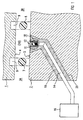
- Figure 1 shows a cross section through part of the wall of a Cover 1 and a lower part 2 of a nuclear reactor pressure vessel, whose interior 3B is on the right in FIG. 1 and whose environment (outside space) 3A is on the left in FIG. 1.
- the lid 1 is drawn in a state in which he - for example during a maintenance and / or Service work or during a revision - from the lower part 2 is lifted off.
- the cover 1 there are two grooves 9 Inclusion of the sealing elements 7, 8 introduced, by means of which the sealing elements 7, 8 during reactor operation, i.e. with cover 1 in place.
- the Sealing elements 7, 8 are drawn in the removed state. They lie on the sealing surface during reactor operation 5 of the lower part 2.
- annular space 10 When lying on the lower part 2 cover 1 is between the sealing surfaces 4, 5 and the sealing elements 7, 8 annular space 10, i.e. an annular space 10 is formed.
- the annular space 10 is only indicated in FIG. 1, since in Figure 1, the lid 1 is shown in the raised state. The annulus 10 is actually during reactor operation much smaller.
- the sealing surface 5 of the lower part is on the cylindrical Part of the nuclear reactor pressure vessel, which is why the two Sealing elements 7, 8 are substantially annular.
- the outer sealing element 7 and the inner Sealing element 8 are arranged essentially concentrically.
- the leakage monitoring line 14 leads through a partial with a filler 19 lined bore 20 in the lower part 2 into the environment 3A of the reactor pressure vessel, where the Detector unit 16 is arranged.
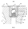
- FIG. 2 shows the area marked in FIG. 1 in an enlarged manner Representation, especially the pressure relief valve 18.
- Das Pressure relief valve 18 comprises a spherical shut-off body 30, which is pressed by a spring 32 against a valve seat 34 is.
- a valve housing 36 is via a welded connection 38 connected to the lower part 2 of the nuclear reactor pressure vessel.
- the pressure relief valve 18 is completely in the wall of the lower part 2 sunk so that the sealing surface 5 of the lower part 2 not from protruding parts of the pressure relief valve 18 is interrupted.
- the spring 32 exerts a spring force on the shut-off body 30 from, the spring force is chosen so large that the shut-off body 30 at a pressure present at the opening 12 more than a predetermined trigger pressure of e.g. 2 bar is pushed away from the valve seat 34 and the pressure relief valve 18 opens.
- a predetermined trigger pressure e.g. 2 bar
- With the maintenance and / or Service work is a water column above the opening 12 at the opening 12 a pressure of less than 2 bar, so that water can enter the Leakage monitoring line 14 is prevented.
Landscapes
- Physics & Mathematics (AREA)
- Engineering & Computer Science (AREA)
- Plasma & Fusion (AREA)
- General Engineering & Computer Science (AREA)
- High Energy & Nuclear Physics (AREA)
- Monitoring And Testing Of Nuclear Reactors (AREA)
- Examining Or Testing Airtightness (AREA)
Claims (5)
- Cuve sous pression d'un réacteur comprenant un couvercle (1), une partie (2) inférieure et un dispositif d'étanchéité interposé entre eux, dans laquellecaractérisée en ce qu'il est prévu dans le conduit (14) de surveillance des fuites une vanne (18) de surpression.le dispositif d'étanchéité comprend deux éléments (7, 8) d'étanchéité,un espace (10) intermédiaire est enfermé entre les éléments (7, 8) d'étanchéité et des surfaces (4, 5) d'étanchéité du couvercle (1) et de la partie (2) inférieure lorsque le couvercle (1) est appliqué etune ouverture (12) ménagée dans l'une des surfaces (5) d'étanchéité communique avec une unité (16) formant détecteur de surveillance des fuites par un conduit (14) de surveillance des fuites,
- Cuve sous pression de réacteur suivant la revendication 1,
caractérisée en ce que la vanne (18) de surpression est disposée sensiblement sur l'ouverture (12). - Cuve sous pression de réacteur suivant la revendication 1 ou 2,
caractérisée en ce que la pression de déclenchement de la vanne (18) de surpression qui, lorsqu'elle est dépassée dans l'espace (10) intermédiaire, fait que la vanne (18) de surpression s'ouvre, est légèrement plus grande qu'une pression maximum prescrite à laquelle on peut s'attendre lors de travaux d'entretien et/ou de service sur l'ouverture (12). - Cuve sous pression de réacteur suivant la revendication 3,
caractérisée en ce que la pression de déclenchement est de 2 bars environ. - Cuve sous pression de réacteur suivant l'une des revendications 1 à 4,
caractérisée en ce que la vanne (18) de surpression est soudée dans la partie (2) inférieure de la cuve sous pression du réacteur.
Applications Claiming Priority (2)
| Application Number | Priority Date | Filing Date | Title |
|---|---|---|---|
| DE19739997 | 1997-09-11 | ||
| DE19739997 | 1997-09-11 |
Publications (3)
| Publication Number | Publication Date |
|---|---|
| EP0902439A2 EP0902439A2 (fr) | 1999-03-17 |
| EP0902439A3 EP0902439A3 (fr) | 1999-06-23 |
| EP0902439B1 true EP0902439B1 (fr) | 2002-08-07 |
Family
ID=7842047
Family Applications (1)
| Application Number | Title | Priority Date | Filing Date |
|---|---|---|---|
| EP98116429A Expired - Lifetime EP0902439B1 (fr) | 1997-09-11 | 1998-08-31 | Cuve sous pression d'un réacteur avec un dispositif de surveillance de fuites |
Country Status (3)
| Country | Link |
|---|---|
| EP (1) | EP0902439B1 (fr) |
| DE (1) | DE59805079D1 (fr) |
| ES (1) | ES2180103T3 (fr) |
Families Citing this family (1)
| Publication number | Priority date | Publication date | Assignee | Title |
|---|---|---|---|---|
| US6349947B1 (en) * | 1999-06-23 | 2002-02-26 | Mve, Inc. | High pressure chamber door seal with leak detection system |
Family Cites Families (5)
| Publication number | Priority date | Publication date | Assignee | Title |
|---|---|---|---|---|
| JPS5912193A (ja) * | 1982-07-13 | 1984-01-21 | Toshiba Corp | 原子炉再循環ポンプの漏洩検出装置 |
| JPS63256893A (ja) * | 1987-04-15 | 1988-10-24 | 株式会社東芝 | 原子炉圧力容器の漏洩検出装置 |
| JPH0371095A (ja) * | 1989-08-11 | 1991-03-26 | Toshiba Corp | 原子炉圧力容器の漏洩検出装置 |
| JPH07318683A (ja) * | 1994-05-25 | 1995-12-08 | Mitsubishi Heavy Ind Ltd | 圧力容器 |
| JPH09113684A (ja) * | 1995-10-19 | 1997-05-02 | Toshiba Eng Co Ltd | 原子力発電プラントの弁ボンネット部漏洩処理装置 |
-
1998
- 1998-08-31 EP EP98116429A patent/EP0902439B1/fr not_active Expired - Lifetime
- 1998-08-31 ES ES98116429T patent/ES2180103T3/es not_active Expired - Lifetime
- 1998-08-31 DE DE59805079T patent/DE59805079D1/de not_active Expired - Lifetime
Also Published As
| Publication number | Publication date |
|---|---|
| EP0902439A2 (fr) | 1999-03-17 |
| EP0902439A3 (fr) | 1999-06-23 |
| ES2180103T3 (es) | 2003-02-01 |
| DE59805079D1 (de) | 2002-09-12 |
Similar Documents
| Publication | Publication Date | Title |
|---|---|---|
| DE3421654C2 (fr) | ||
| DE3519773A1 (de) | Steckverbindung fuer bohrgestaenge von erdbohrgeraeten | |
| DE3402832A1 (de) | Versandbehaelter fuer radioaktive oder andere gefaehrliche materialien | |
| DE3303486A1 (de) | Dichtungseinrichtung mit unmittelbarer metallberuehrung | |
| DE2904403A1 (de) | Antikavitations- und ueberlastungsschutz-absperrorgan fuer hydraulikeinrichtungen | |
| DE1904463A1 (de) | Stroemungsmitteldichter Verschluss fuer Kernreaktoren | |
| DE1948522B2 (de) | Sicherheitsvorrichtung fuer druckbehaelter von atomkernreaktoren | |
| DE1097048B (de) | Kernreaktoranlage mit Druckbehaelter | |
| WO2010084122A1 (fr) | Procédé et dispositif permettant d'entourer de manière étanche au gaz au moins une barre de combustible | |
| CH690877A5 (de) | Siedewasserreaktor mit einem Sicherheitsbehälter mit unterteiltem Flutbeckenraum. | |
| WO2010069710A1 (fr) | Convertisseur de mesure de pression différentielle | |
| DE2441999B2 (de) | Sicherheitsbehälter für einen schnellen, natriumgekühlten Kernreaktor | |
| DE2634295C3 (de) | Kernreaktoranlage | |
| EP0902439B1 (fr) | Cuve sous pression d'un réacteur avec un dispositif de surveillance de fuites | |
| DE2935605A1 (de) | Stopfen, insbesondere fuer leitungsrohre bei offshore-bohrinseln | |
| CH689240A5 (de) | Kernrohr- und Tragplattenbaueinheit fuer Druckwasserkernreaktor. | |
| EP1248270A1 (fr) | Bouchon d'obturation pour tube destiné à contenir un barreau de combustible et ensemble d'encapsulage pour barreau de combustible nucléaire | |
| DE3740359A1 (de) | Verfahren zur herstellung von kontakten in fluessigkeiten und vorrichtung hierfuer | |
| DE2159677C2 (de) | Druckbehälter aus vorgespanntem Beton, insbesondere für einen Kernreaktor | |
| DE2919797C2 (de) | Lager für die Aufbewahrung abgebrannter Brennelemente | |
| DE1227577B (de) | Kernreaktoranlage mit gasdichtem Behaelteraufbau | |
| DE2837631C2 (fr) | ||
| DE2828973C2 (de) | Aus einem Tragdeckel und einem Dichtdeckel bestehende Verschlußvorrichtung für eine große Behälterdurchführung | |
| EP0090941B1 (fr) | Dispositif de sûreté contre la rupture de tuyaux souples pour fluides notamment pour installations de gaz | |
| DE1169228B (de) | Abdichtungsstopfen fuer die Bohrung eines aufrecht stehenden Rohres |
Legal Events
| Date | Code | Title | Description |
|---|---|---|---|
| PUAI | Public reference made under article 153(3) epc to a published international application that has entered the european phase |
Free format text: ORIGINAL CODE: 0009012 |
|
| AK | Designated contracting states |
Kind code of ref document: A2 Designated state(s): BE CH DE ES FR LI |
|
| AX | Request for extension of the european patent |
Free format text: AL;LT;LV;MK;RO;SI |
|
| PUAL | Search report despatched |
Free format text: ORIGINAL CODE: 0009013 |
|
| AK | Designated contracting states |
Kind code of ref document: A3 Designated state(s): AT BE CH CY DE DK ES FI FR GB GR IE IT LI LU MC NL PT SE |
|
| AX | Request for extension of the european patent |
Free format text: AL;LT;LV;MK;RO;SI |
|
| 17P | Request for examination filed |
Effective date: 19990720 |
|
| AKX | Designation fees paid |
Free format text: BE CH DE ES FR LI |
|
| RAP1 | Party data changed (applicant data changed or rights of an application transferred) |
Owner name: FRAMATOME ANP GMBH |
|
| 17Q | First examination report despatched |
Effective date: 20011018 |
|
| GRAG | Despatch of communication of intention to grant |
Free format text: ORIGINAL CODE: EPIDOS AGRA |
|
| RTI1 | Title (correction) |
Free format text: REACTOR PRESSURE VESSEL COMPRISING A LEAKAGE MONITORING DEVICE |
|
| GRAG | Despatch of communication of intention to grant |
Free format text: ORIGINAL CODE: EPIDOS AGRA |
|
| GRAH | Despatch of communication of intention to grant a patent |
Free format text: ORIGINAL CODE: EPIDOS IGRA |
|
| GRAH | Despatch of communication of intention to grant a patent |
Free format text: ORIGINAL CODE: EPIDOS IGRA |
|
| GRAA | (expected) grant |
Free format text: ORIGINAL CODE: 0009210 |
|
| AK | Designated contracting states |
Kind code of ref document: B1 Designated state(s): BE CH DE ES FR LI |
|
| REG | Reference to a national code |
Ref country code: CH Ref legal event code: EP |
|
| REG | Reference to a national code |
Ref country code: CH Ref legal event code: NV Representative=s name: E. BLUM & CO. PATENTANWAELTE |
|
| REF | Corresponds to: |
Ref document number: 59805079 Country of ref document: DE Date of ref document: 20020912 |
|
| REG | Reference to a national code |
Ref country code: ES Ref legal event code: FG2A Ref document number: 2180103 Country of ref document: ES Kind code of ref document: T3 |
|
| ET | Fr: translation filed | ||
| PLBE | No opposition filed within time limit |
Free format text: ORIGINAL CODE: 0009261 |
|
| STAA | Information on the status of an ep patent application or granted ep patent |
Free format text: STATUS: NO OPPOSITION FILED WITHIN TIME LIMIT |
|
| 26N | No opposition filed |
Effective date: 20030508 |
|
| REG | Reference to a national code |
Ref country code: CH Ref legal event code: PFA Owner name: AREVA NP GMBH Free format text: FRAMATOME ANP GMBH#FREYESLEBENSTRASSE 1#91050 ERLANGEN (DE) -TRANSFER TO- AREVA NP GMBH#FREYESLEBENSTRASSE 1#91058 ERLANGEN (DE) |
|
| REG | Reference to a national code |
Ref country code: FR Ref legal event code: CD |
|
| REG | Reference to a national code |
Ref country code: CH Ref legal event code: PFA Owner name: AREVA NP GMBH Free format text: AREVA NP GMBH#FREYESLEBENSTRASSE 1#91058 ERLANGEN (DE) -TRANSFER TO- AREVA NP GMBH#FREYESLEBENSTRASSE 1#91058 ERLANGEN (DE) |
|
| REG | Reference to a national code |
Ref country code: CH Ref legal event code: PCOW Free format text: AREVA NP GMBH;PAUL-GOSSEN-STRASSE 100;91052 ERLANGEN (DE) |
|
| REG | Reference to a national code |
Ref country code: FR Ref legal event code: CA |
|
| REG | Reference to a national code |
Ref country code: DE Ref legal event code: R082 Ref document number: 59805079 Country of ref document: DE Representative=s name: MOERTEL, ALFRED, DIPL.-PHYS. DR.RER.NAT., DE |
|
| REG | Reference to a national code |
Ref country code: DE Ref legal event code: R082 Ref document number: 59805079 Country of ref document: DE Representative=s name: MEISSNER BOLTE PATENTANWAELTE RECHTSANWAELTE P, DE Effective date: 20131112 Ref country code: DE Ref legal event code: R082 Ref document number: 59805079 Country of ref document: DE Representative=s name: MEISSNER BOLTE & PARTNER GBR, DE Effective date: 20131112 Ref country code: DE Ref legal event code: R082 Ref document number: 59805079 Country of ref document: DE Representative=s name: MOERTEL, ALFRED, DIPL.-PHYS. DR.RER.NAT., DE Effective date: 20131112 Ref country code: DE Ref legal event code: R081 Ref document number: 59805079 Country of ref document: DE Owner name: AREVA GMBH, DE Free format text: FORMER OWNER: AREVA NP GMBH, 91052 ERLANGEN, DE Effective date: 20131112 |
|
| REG | Reference to a national code |
Ref country code: DE Ref legal event code: R082 Ref document number: 59805079 Country of ref document: DE Representative=s name: MEISSNER BOLTE PATENTANWAELTE RECHTSANWAELTE P, DE Ref country code: DE Ref legal event code: R082 Ref document number: 59805079 Country of ref document: DE Representative=s name: MEISSNER BOLTE & PARTNER GBR, DE |
|
| REG | Reference to a national code |
Ref country code: FR Ref legal event code: PLFP Year of fee payment: 18 |
|
| PGFP | Annual fee paid to national office [announced via postgrant information from national office to epo] |
Ref country code: CH Payment date: 20150824 Year of fee payment: 18 Ref country code: ES Payment date: 20150825 Year of fee payment: 18 Ref country code: DE Payment date: 20150820 Year of fee payment: 18 |
|
| PGFP | Annual fee paid to national office [announced via postgrant information from national office to epo] |
Ref country code: BE Payment date: 20150820 Year of fee payment: 18 Ref country code: FR Payment date: 20150824 Year of fee payment: 18 |
|
| REG | Reference to a national code |
Ref country code: DE Ref legal event code: R082 Ref document number: 59805079 Country of ref document: DE Representative=s name: MEISSNER BOLTE PATENTANWAELTE RECHTSANWAELTE P, DE |
|
| PG25 | Lapsed in a contracting state [announced via postgrant information from national office to epo] |
Ref country code: BE Free format text: LAPSE BECAUSE OF NON-PAYMENT OF DUE FEES Effective date: 20160831 |
|
| REG | Reference to a national code |
Ref country code: DE Ref legal event code: R119 Ref document number: 59805079 Country of ref document: DE |
|
| REG | Reference to a national code |
Ref country code: CH Ref legal event code: PL |
|
| PG25 | Lapsed in a contracting state [announced via postgrant information from national office to epo] |
Ref country code: CH Free format text: LAPSE BECAUSE OF NON-PAYMENT OF DUE FEES Effective date: 20160831 Ref country code: LI Free format text: LAPSE BECAUSE OF NON-PAYMENT OF DUE FEES Effective date: 20160831 |
|
| REG | Reference to a national code |
Ref country code: FR Ref legal event code: ST Effective date: 20170428 |
|
| PG25 | Lapsed in a contracting state [announced via postgrant information from national office to epo] |
Ref country code: FR Free format text: LAPSE BECAUSE OF NON-PAYMENT OF DUE FEES Effective date: 20160831 Ref country code: DE Free format text: LAPSE BECAUSE OF NON-PAYMENT OF DUE FEES Effective date: 20170301 |
|
| PG25 | Lapsed in a contracting state [announced via postgrant information from national office to epo] |
Ref country code: ES Free format text: LAPSE BECAUSE OF NON-PAYMENT OF DUE FEES Effective date: 20160831 |
|
| REG | Reference to a national code |
Ref country code: ES Ref legal event code: FD2A Effective date: 20180627 |
|
| PG25 | Lapsed in a contracting state [announced via postgrant information from national office to epo] |
Ref country code: ES Free format text: LAPSE BECAUSE OF NON-PAYMENT OF DUE FEES Effective date: 20160901 |