EP0902439B1 - Reactor pressure vessel comprising a leakage monitoring device - Google Patents
Reactor pressure vessel comprising a leakage monitoring device Download PDFInfo
- Publication number
- EP0902439B1 EP0902439B1 EP98116429A EP98116429A EP0902439B1 EP 0902439 B1 EP0902439 B1 EP 0902439B1 EP 98116429 A EP98116429 A EP 98116429A EP 98116429 A EP98116429 A EP 98116429A EP 0902439 B1 EP0902439 B1 EP 0902439B1
- Authority
- EP
- European Patent Office
- Prior art keywords
- pressure vessel
- relief valve
- leakage monitoring
- pressure
- reactor pressure
- Prior art date
- Legal status (The legal status is an assumption and is not a legal conclusion. Google has not performed a legal analysis and makes no representation as to the accuracy of the status listed.)
- Expired - Lifetime
Links
Images
Classifications
-
- G—PHYSICS
- G21—NUCLEAR PHYSICS; NUCLEAR ENGINEERING
- G21C—NUCLEAR REACTORS
- G21C17/00—Monitoring; Testing ; Maintaining
- G21C17/002—Detection of leaks
-
- G—PHYSICS
- G21—NUCLEAR PHYSICS; NUCLEAR ENGINEERING
- G21C—NUCLEAR REACTORS
- G21C13/00—Pressure vessels; Containment vessels; Containment in general
- G21C13/02—Details
- G21C13/06—Sealing-plugs
- G21C13/073—Closures for reactor-vessels, e.g. rotatable
- G21C13/0735—Seals for closures or for rotatable closures
-
- Y—GENERAL TAGGING OF NEW TECHNOLOGICAL DEVELOPMENTS; GENERAL TAGGING OF CROSS-SECTIONAL TECHNOLOGIES SPANNING OVER SEVERAL SECTIONS OF THE IPC; TECHNICAL SUBJECTS COVERED BY FORMER USPC CROSS-REFERENCE ART COLLECTIONS [XRACs] AND DIGESTS
- Y02—TECHNOLOGIES OR APPLICATIONS FOR MITIGATION OR ADAPTATION AGAINST CLIMATE CHANGE
- Y02E—REDUCTION OF GREENHOUSE GAS [GHG] EMISSIONS, RELATED TO ENERGY GENERATION, TRANSMISSION OR DISTRIBUTION
- Y02E30/00—Energy generation of nuclear origin
- Y02E30/30—Nuclear fission reactors
Definitions
- the pressure vessel of a nuclear reactor containing the reactor core generally consists of at least one essentially cylindrical bottom and a lid.
- the lid On the contact surface of the lid on the lower part is the lid opposite the lower part sealed by a gasket that the high temperature and high pressure inside the closed Nuclear reactor pressure vessel during reactor operation withstand.
- the seal consists of two sealing elements, the course of sealing surfaces on the contact surface follow between cover and base. Because of the essentially The sealing elements are cylindrical in shape of the lower part approximately ring-shaped. One of the sealing elements has a smaller diameter than the other Sealing element on and is usually concentric to that another sealing element arranged. From the sealing elements and from the sealing surfaces of the lid and the lower part an intermediate space is enclosed in the form of an annular space, if the lid is over the sealing elements the lower part rests.
- Such a leakage monitoring device is e.g. out "Patent Abstracts of Japan", P-1215, June 14, 1991, Vol. 15, No. 234 under JP 3-71095 (A).
- the cover is removed from the lower part and often the entire reactor pit in which the Nuclear reactor pressure vessel is located, with water from the primary circuit flooded. This often leads to an undesired one Primary water penetration into the leakage monitoring line. It is known to penetrate primary water to counteract that during the Work a stopper or a closure into the opening in the sealing surface on the lower part of the Reactor pressure vessel is inserted. But this only works insufficient, as there are always times, albeit very often short, during which the opening is unlocked.
- the invention has for its object a Reactor pressure vessel with a leakage monitoring device specify the disadvantages described are avoided and in particular wetting the detector unit with primary water and an entry of primary water into the Leakage monitoring line during the Work more extensively, reliably and ergonomically prevented than this with the known leakage monitoring devices combined with the previously common Procedure is the case.
- the advantage is that wetting the Detector unit with primary water completely and reliably is avoided. It is also particularly advantageous that the usual insertion of plugs into the opening is unnecessary. The plugging and unplugging was done so far e.g. using complex and remote-controlled Operating tools performed, it too Damage to the sealing surfaces could occur. This cumbersome operations are with a leakage monitoring device no longer necessary according to the invention.
- the reactor pressure vessel designed according to the invention leads also to minimize the radioactive dose for the Operating personnel because the pressure relief valve unlike the So far only usual plugs once and not for all Maintenance or service work must be carried out again. By eliminating work steps, one becomes Reduction of revision time and thus a possibly immense cost savings achieved for the nuclear power plant in question.
- pressure relief valve used for the description generally stands for a closure device, which at Reaching a one-sided trigger pressure, or especially when a trigger pressure difference between bilateral connections of the closure device, opens. Opening can be automatic as well as externally controlled respectively.
- the pressure relief valve can e.g. a pressure relief valve his.
- the pressure relief valve is preferably essentially at the opening arranged. This advantageously does not only prevents wetting of the detector unit with primary water, rather, the entry of primary water already avoided from the opening.
- the leakage monitoring line can use it over its entire length of primary water be kept free.
- the Release pressure of the pressure relief valve when it is exceeded the pressure relief valve in the gap opens, slightly higher as a predetermined maximum pressure, the maintenance and / or Service work on the opening is expected.
- the design is, among other things, the knowledge based on the fact that the function of a leakage monitoring device still ensured for a nuclear reactor pressure vessel is, if only such leaks are recognized that lead to a pressure in the space above a certain one Limit pressure. Another finding exists in that the pressure generated during maintenance and / or service work expected at the opening, below this Limit pressure. This limit pressure is called the trigger pressure of the pressure relief valve selected.
- the intended pressure relief valve can therefore prevent the entry of primary water into the Connection between the opening and the detector unit installed be without the function of the detector unit during to influence the ongoing reactor operation.
- the installation the pressure relief valve can also be retrofitted into an already existing leakage monitoring device.
- the release pressure of the pressure relief valve is approx. 2 bar.
- the pressure relief valve can e.g. in the lower part of the nuclear reactor pressure vessel be welded in. Such an arrangement offers the advantage of special stability and ease of maintenance.
- the pressure relief valve can be flush with the sealing surface complete the lower part so that the pressure relief valve is completely sunk in the lower part, and the i.a. flat sealing surface not interrupted by protruding parts is.
- This is an unrestricted advantage Cleaning of the sealing surfaces possible.
- the sealing surface can then during the maintenance and / or Service work in a simple way with a sealing surface protection be provided.
- the output signal of the detector unit is preferably at built-in pressure relief valve recorded.
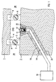
- Figure 1 shows a cross section through part of the wall of a Cover 1 and a lower part 2 of a nuclear reactor pressure vessel, whose interior 3B is on the right in FIG. 1 and whose environment (outside space) 3A is on the left in FIG. 1.
- the lid 1 is drawn in a state in which he - for example during a maintenance and / or Service work or during a revision - from the lower part 2 is lifted off.
- the cover 1 there are two grooves 9 Inclusion of the sealing elements 7, 8 introduced, by means of which the sealing elements 7, 8 during reactor operation, i.e. with cover 1 in place.
- the Sealing elements 7, 8 are drawn in the removed state. They lie on the sealing surface during reactor operation 5 of the lower part 2.
- annular space 10 When lying on the lower part 2 cover 1 is between the sealing surfaces 4, 5 and the sealing elements 7, 8 annular space 10, i.e. an annular space 10 is formed.
- the annular space 10 is only indicated in FIG. 1, since in Figure 1, the lid 1 is shown in the raised state. The annulus 10 is actually during reactor operation much smaller.
- the sealing surface 5 of the lower part is on the cylindrical Part of the nuclear reactor pressure vessel, which is why the two Sealing elements 7, 8 are substantially annular.
- the outer sealing element 7 and the inner Sealing element 8 are arranged essentially concentrically.
- the leakage monitoring line 14 leads through a partial with a filler 19 lined bore 20 in the lower part 2 into the environment 3A of the reactor pressure vessel, where the Detector unit 16 is arranged.
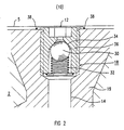
- FIG. 2 shows the area marked in FIG. 1 in an enlarged manner Representation, especially the pressure relief valve 18.
- Das Pressure relief valve 18 comprises a spherical shut-off body 30, which is pressed by a spring 32 against a valve seat 34 is.
- a valve housing 36 is via a welded connection 38 connected to the lower part 2 of the nuclear reactor pressure vessel.
- the pressure relief valve 18 is completely in the wall of the lower part 2 sunk so that the sealing surface 5 of the lower part 2 not from protruding parts of the pressure relief valve 18 is interrupted.
- the spring 32 exerts a spring force on the shut-off body 30 from, the spring force is chosen so large that the shut-off body 30 at a pressure present at the opening 12 more than a predetermined trigger pressure of e.g. 2 bar is pushed away from the valve seat 34 and the pressure relief valve 18 opens.
- a predetermined trigger pressure e.g. 2 bar
- With the maintenance and / or Service work is a water column above the opening 12 at the opening 12 a pressure of less than 2 bar, so that water can enter the Leakage monitoring line 14 is prevented.
Description
Die Erfindung betrifft einen Reaktordruckbehälter mit einer Leckageüberwachungseinrichtung für eine Dichtung zwischen dem Deckel und dem Unterteil des Reaktordruckbehälters, wobei
- die Dichtung zwei Dichtungselemente aufweist,
- von den Dichtungselementen und von Dichtungsflächen des Deckels und des Unterteils bei aufliegendem Deckel ein Zwischenraum eingeschlossen ist, und
- eine Öffnung in einer der Dichtungsflächen mit einer Detektoreinheit zur Leckageüberwachung über eine Leckageüberwachungsleitung in Verbindung steht.
- the seal has two sealing elements,
- a space is enclosed by the sealing elements and sealing surfaces of the cover and the lower part when the cover is in place, and
- an opening in one of the sealing surfaces is connected to a detector unit for leakage monitoring via a leakage monitoring line.
Der den Reaktorkern beinhaltende Druckbehälter eines Kernreaktors besteht im allgemeinen wenigstens aus einem im wesentlichen zylindrischen Unterteil und einem Deckel. An der Auflagefläche des Deckels auf dem Unterteil ist der Deckel gegenüber dem Unterteil durch eine Dichtung abgedichtet, die der hohen Temperatur und dem hohen Druck im Inneren des geschlossenen Kernreaktordruckbehälters während des Reaktorbetriebs standhält. Die Dichtung besteht aus zwei Dichtungselementen, die dem Verlauf von Dichtungsflächen auf der Auflagefläche zwischen Deckel und Unterteil folgen. Wegen der im wesentlichen zylindrischen Form des Unterteils sind die Dichtungselemente näherungsweise ringförmig. Eines der Dichtungselemente weist einen geringeren Durchmesser als das andere Dichtungselement auf und ist in der Regel konzentrisch zu dem anderen Dichtungselement angeordnet. Von den Dichtungselementen und von den Dichtungsflächen des Deckels und des Unterteils ist ein Zwischenraum in Form eines Ringraumes eingeschlossen, falls der Deckel über die Dichtungselemente auf dem Unterteil aufliegt.The pressure vessel of a nuclear reactor containing the reactor core generally consists of at least one essentially cylindrical bottom and a lid. On the contact surface of the lid on the lower part is the lid opposite the lower part sealed by a gasket that the high temperature and high pressure inside the closed Nuclear reactor pressure vessel during reactor operation withstand. The seal consists of two sealing elements, the course of sealing surfaces on the contact surface follow between cover and base. Because of the essentially The sealing elements are cylindrical in shape of the lower part approximately ring-shaped. One of the sealing elements has a smaller diameter than the other Sealing element on and is usually concentric to that another sealing element arranged. From the sealing elements and from the sealing surfaces of the lid and the lower part an intermediate space is enclosed in the form of an annular space, if the lid is over the sealing elements the lower part rests.
In der Dichtungsfläche des Unterteils befindet sich eine Öffnung, die über eine durch die Wand des Unterteils führende Leckageüberwachungsleitung mit einer Detektoreinheit zur Leckageüberwachung in Verbindung steht. Eine in seltenen Fällen auftretende Undichtigkeit an dem innenliegenden Dichtungselement mit kleinerem Durchmesser ist bei einer solchen Anordnung mittels der Detektoreinheit erkennbar.There is an opening in the sealing surface of the lower part, the one leading through the wall of the lower part Leakage monitoring line with a detector unit Leakage monitoring is connected. One in rare cases Leakage occurring on the internal sealing element with a smaller diameter is one Arrangement recognizable by means of the detector unit.
Eine derartige Leckageüberwachungseinrichtung ist z.B. aus "Patent Abstracts of Japan", P-1215, June 14, 1991, Vol. 15, No. 234 unter JP 3-71095 (A), bekannt.Such a leakage monitoring device is e.g. out "Patent Abstracts of Japan", P-1215, June 14, 1991, Vol. 15, No. 234 under JP 3-71095 (A).
Bei Wartungs- und/oder Servicearbeiten oder bei einer Revision im Kernkraftwerk wird der Deckel von dem Unterteil abgenommen und oftmals die gesamte Reaktorgrube, in der sich der Kernreaktordruckbehälter befindet, mit Wasser aus dem Primärkreislauf geflutet. Dabei kommt es häufig zu einem ungewünschten Eindringen von Primärwasser in die Leckageüberwachungsleitung. Es ist bekannt, dem Eindringen von Primärwasser dadurch entgegenzuwirken, dass während der durchzuführenden Arbeiten ein Stopfen oder ein Verschluss in die Öffnung in der Dichtfläche auf dem Unterteil des Reaktordruckbehälters gesteckt wird. Dies gelingt aber nur ungenügend, da es immer Zeiten gibt, wenngleich auch sehr kurze, während derer die Öffnung unverschlossen ist.During maintenance and / or service work or during a revision in the nuclear power plant, the cover is removed from the lower part and often the entire reactor pit in which the Nuclear reactor pressure vessel is located, with water from the primary circuit flooded. This often leads to an undesired one Primary water penetration into the leakage monitoring line. It is known to penetrate primary water to counteract that during the Work a stopper or a closure into the opening in the sealing surface on the lower part of the Reactor pressure vessel is inserted. But this only works insufficient, as there are always times, albeit very often short, during which the opening is unlocked.
Der Erfindung liegt die Aufgabe zugrunde, einen Reaktordruckbehälter mit einer Leckageüberwachungseinrichtung anzugeben, bei dem die beschriebenen Nachteile vermieden sind und bei dem insbesondere eine Benetzung der Detektoreinheit mit Primärwasser und einen Eintrag von Primärwasser in die Leckageüberwachungsleitung während der durchzuführenden Arbeiten weitgehender, zuverlässiger und ergonomischer verhindert als dies bei den bekannten Leckageüberwachungseinrichtungen verbunden mit der bislang üblichen Vorgehensweise der Fall ist.The invention has for its object a Reactor pressure vessel with a leakage monitoring device specify the disadvantages described are avoided and in particular wetting the detector unit with primary water and an entry of primary water into the Leakage monitoring line during the Work more extensively, reliably and ergonomically prevented than this with the known leakage monitoring devices combined with the previously common Procedure is the case.
Zur Lösung der Aufgabe ist in der Leckageüberwachungsleitung des Druckbehälters ein Überdruckventil angeordnet. To solve the problem is in the leakage monitoring line arranged a pressure relief valve of the pressure vessel.
Der Vorteil besteht darin, daß eine Benetzung der Detektoreinheit mit Primärwasser vollständig und zuverlässig vermieden ist. Von besonderem Vorteil ist gleichfalls, dass das bislang übliche Einstecken von Stopfen in die Öffnung unnötig ist. Das Einstecken und Entfernen der Stopfen wurde bislang z.B. mittels aufwendigen und ferngesteuerten Bedienwerkzeugen durchgeführt, wobei es auch zu Beschädigungen der Dichtungsflächen kommen konnte. Diese umständlichen Arbeitsvorgänge sind bei einer Leckageüberwachungseinrichtung nach der Erfindung nicht mehr nötig.The advantage is that wetting the Detector unit with primary water completely and reliably is avoided. It is also particularly advantageous that the usual insertion of plugs into the opening is unnecessary. The plugging and unplugging was done so far e.g. using complex and remote-controlled Operating tools performed, it too Damage to the sealing surfaces could occur. This cumbersome operations are with a leakage monitoring device no longer necessary according to the invention.
Bei der bislang üblichen Vorgehensweise hätte auch das Wiederentfernen der Stopfen vor dem Wiederaufsetzen des Deckels auf das Unterteil des Kernreaktordruckbehälters vergessen werden können, wodurch eine Inbetriebnahme des Kernreaktors zunächst nicht möglich gewesen wäre. Eine Verlängerung der Unterbrechung des Betriebs des Kernreaktors wäre die Folge gewesen, möglicherweise verbunden mit Beschädigungen am Deckel oder mit Störungen. Im ungünstigsten Fall hätte das Vergessen des Entfernens des Stopfens - obgleich mit sehr geringer Wahrscheinlichkeit - bei dem nachfolgenden Reaktorbetrieb zu einem Ausfall der betreffenden Leckageüberwachungseinrichtung führen können. Dieses Risiko wird mit einer Leckageüberwachungseinrichtung nach der Erfindung in vorteilhafter Weise vermieden.With the usual procedure so far, that would also have been the case Remove the plugs before replacing the cover forget about the lower part of the nuclear reactor pressure vessel can be, thereby starting up the nuclear reactor would not have been possible at first. An extension the shutdown of the operation of the nuclear reactor would be the Result, possibly associated with damage to the Cover or with faults. In the worst case, that would have been Forget about removing the plug - albeit with very little Probability - in the subsequent reactor operation to a failure of the leakage monitoring device in question being able to lead. This risk comes with a Leakage monitoring device according to the invention in an advantageous manner Avoided way.
Der erfindungsgemäß ausgestaltete Reaktordruckbehälter führt auch zu einer Minimierung der radioaktiven Dosis für das Betriebspersonal, da das Überdruckventil im Gegensatz zu den bislang üblichen Stopfen nur einmalig, und nicht bei allen Wartungs- oder Servicearbeiten erneut, angebracht werden muß. Durch den Wegfall von Arbeitsschritten wird auch eine Revisionszeitverkürzung und damit eine u.U. immense Kostenersparnis für das betreffende Kernkraftwerk erreicht. The reactor pressure vessel designed according to the invention leads also to minimize the radioactive dose for the Operating personnel because the pressure relief valve unlike the So far only usual plugs once and not for all Maintenance or service work must be carried out again. By eliminating work steps, one becomes Reduction of revision time and thus a possibly immense cost savings achieved for the nuclear power plant in question.
Der zur Beschreibung verwendete Begriff "Überdruckventil" steht allgemein für eine Verschlusseinrichtung, die sich bei Erreichen eines einseitig anliegenden Auslösedruckes, bzw. insbesondere bei Erreichen einer Auslösedruckdifferenz zwischen beiderseitigen Anschlüssen der Verschlusseinrichtung, öffnet. Das Öffnen kann sowohl selbsttätig als auch fremdgesteuert erfolgen. Das Überdruckventil kann z.B. ein Druckbegrenzungsventil sein.The term "pressure relief valve" used for the description generally stands for a closure device, which at Reaching a one-sided trigger pressure, or especially when a trigger pressure difference between bilateral connections of the closure device, opens. Opening can be automatic as well as externally controlled respectively. The pressure relief valve can e.g. a pressure relief valve his.
Bevorzugt ist das Überdruckventil im wesentlichen an der Öffnung angeordnet. Dadurch wird in vorteilhafter Weise nicht nur eine Benetzung der Detektoreinheit mit Primärwasser verhindert, sondern vielmehr der Eintrag von Primärwasser bereits ab der Öffnung vermieden. Die Leckageüberwachungsleitung kann damit über ihre gesamte Länge von Primärwasser freigehalten werden.The pressure relief valve is preferably essentially at the opening arranged. This advantageously does not only prevents wetting of the detector unit with primary water, rather, the entry of primary water already avoided from the opening. The leakage monitoring line can use it over its entire length of primary water be kept free.
Nach einer besonders bevorzugten Ausgestaltung ist der Auslösedruck des Überdruckventils, bei dessen Überschreiten im Zwischenraum das Überdruckventil öffnet, geringfügig höher als ein vorgegebener Maximaldruck, der bei Wartungs- und/oder Servicearbeiten an der Öffnung zu erwarten ist.According to a particularly preferred embodiment, the Release pressure of the pressure relief valve when it is exceeded the pressure relief valve in the gap opens, slightly higher as a predetermined maximum pressure, the maintenance and / or Service work on the opening is expected.
Der Ausgestaltung liegt nämlich unter anderem die Erkenntnis zugrunde, daß die Funktion einer Leckageüberwachungseinrichtung für einen Kernreaktordruckbehälter auch dann noch sichergestellt ist, falls nur solche Lecks erkannt werden, die zu einem Druck im Zwischenraum führen, der oberhalb eines bestimmten Grenzdruckes liegt. Eine weitere Erkenntnis besteht darin, dass der Druck, der bei Wartungs- und/oder Servicearbeiten an der Öffnung zu erwarten ist, unterhalb dieses Grenzdrucks liegt. Dieser Grenzdruck wird als Auslösedruck des Überdruckventils gewählt. Das vorgesehene Überdruckventil kann deshalb zur Vermeidung von Primärwassereintrag- in die Verbindung zwischen der Öffnung und der Detektoreinheit eingebaut werden, ohne die Funktion der Detektoreinheit während des laufenden Reaktorbetriebes zu beeinflussen. Der Einbau des Überdruckventils kann auch nachträglich in eine bereits bestehende Leckageüberwachungseinrichtung erfolgen.The design is, among other things, the knowledge based on the fact that the function of a leakage monitoring device still ensured for a nuclear reactor pressure vessel is, if only such leaks are recognized that lead to a pressure in the space above a certain one Limit pressure. Another finding exists in that the pressure generated during maintenance and / or service work expected at the opening, below this Limit pressure. This limit pressure is called the trigger pressure of the pressure relief valve selected. The intended pressure relief valve can therefore prevent the entry of primary water into the Connection between the opening and the detector unit installed be without the function of the detector unit during to influence the ongoing reactor operation. The installation the pressure relief valve can also be retrofitted into an already existing leakage monitoring device.
Beispielsweise beträgt der Auslösedruck des Überdruckventils ca. 2 bar.For example, the release pressure of the pressure relief valve is approx. 2 bar.
Das Überdruckventil kann z.B. in das Unterteil des Kernreaktordruckbehälters eingeschweißt sein. Eine solche Anordnung bietet den Vorteil der besonderen Stabilität und Wartungsfreundlichkeit.The pressure relief valve can e.g. in the lower part of the nuclear reactor pressure vessel be welded in. Such an arrangement offers the advantage of special stability and ease of maintenance.
Insbesondere kann das Überdruckventil bündig mit der Dichtungsfläche des Unterteils abschließen, so daß das Überdruckventil vollständig im Unterteil versenkt ist, und die i.a. ebene Dichtungsfläche nicht durch überstehende Teile unterbrochen ist. Dadurch ist in vorteilhafter Weise eine uneingeschränkte Reinigung der Dichtungsflächen möglich. Die Dichtungsfläche kann dann während der durchzuführenden Wartungsund/oder Servicearbeiten auf einfache Weise mit einem Dichtungsflächenschutz versehen werden.In particular, the pressure relief valve can be flush with the sealing surface complete the lower part so that the pressure relief valve is completely sunk in the lower part, and the i.a. flat sealing surface not interrupted by protruding parts is. This is an unrestricted advantage Cleaning of the sealing surfaces possible. The sealing surface can then during the maintenance and / or Service work in a simple way with a sealing surface protection be provided.
Vorzugsweise wird das Ausgangssignal der Detektoreinheit bei eingebautem Überdruckventil aufgezeichnet.The output signal of the detector unit is preferably at built-in pressure relief valve recorded.
Ein Ausführungsbeispiel eines Reaktordruckbehälters mit einer Leckageüberwachungseinrichtung wird anhand der beiden Figuren näher erläutert. Dabei zeigt:
- FIG 1
- einen Ausschnitt eines Querschnitts durch einen Reaktordruckbehälter und
- FIG 2
- eine vergrößerte Darstellung des in
Figur 1 gekennzeichneten Ausschnitts II.
- FIG. 1
- a section of a cross section through a reactor pressure vessel and
- FIG 2
- an enlarged view of the section II marked in Figure 1.
Figur 1 zeigt einen Querschnitt durch einen Teil der Wand eines
Deckels 1 und eines Unterteils 2 eines Kernreaktordruckbehälters,
dessen Innenraum 3B sich in Figur 1 rechts und
dessen Umgebung (Außenraum) 3A sich in Figur 1 links befindet.Figure 1 shows a cross section through part of the wall of a
Zwischen einer Dichtungsfläche 4 des Deckels 1 und einer
Dichtungsfläche 5 des Unterteils 2 sind zwei Dichtungselemente
7, 8 angeordnet. Der Deckel 1 ist in einem Zustand gezeichnet,
in dem er - beispielsweise bei einer Wartungsund/oder
Servicearbeit oder bei einer Revision - von dem Unterteil
2 abgehoben ist. Im Deckel 1 sind zwei Nuten 9 zur
Aufnahme der Dichtungselemente 7, 8 eingebracht, mittels derer
die Dichtungselemente 7, 8 während des Reaktorbetriebes,
d.h. bei aufgesetztem Deckel 1, in Lage gehalten sind. Die
Dichtungselemente 7, 8 sind im ausgebauten Zustand gezeichnet.
Sie liegen während des Reaktorbetriebes auf der Dichtungsfläche
5 des Unterteils 2 auf.Between a sealing
Bei auf dem Unterteil 2 aufliegendem Deckel 1 ist zwischen
den Dichtungsflächen 4, 5 und den Dichtungselementen 7, 8 ein
ringförmiger Zwischenraum 10, d.h. ein Ringraum 10, gebildet.
Der Ringraum 10 ist in Figur 1 lediglich angedeutet, da in
Figur 1 der Deckel 1 in abgehobenem Zustand dargestellt ist.
Der Ringraum 10 ist während des Reaktorbetriebes tatsächlich
sehr viel kleiner.When lying on the
Die Dichtungsfläche 5 des Unterteils befindet sich am zylindrischen
Teil des Kernreaktordruckbehälters, weshalb die beiden
Dichtungselemente 7, 8 im wesentlichen ringförmig sind.
Das außenliegende Dichtungselement 7 und das innenliegende
Dichtungselement 8 sind im wesentlichen konzentrisch angeordnet. The sealing
Eine Öffnung 12 in der Dichtungsfläche 5 des Unterteils 2 ist
über eine Leckageüberwachungsleitung 14 mit einer Detektoreinheit
16 zur Leckageüberwachung-verbunden. Unmittelbar
an der Öffnung 12 ist in die Leckageüberwachungsleitung 14
ein Überdruckventil 18 eingeschweißt.There is an
Die Leckageüberwachungsleitung 14 führt durch eine teilweise
mit einem Füllmaterial 19 ausgekleidete Bohrung 20 im Unterteil
2 in die Umgebung 3A des Reaktordruckbehälters, wo die
Detektoreinheit 16 angeordnet ist.The
Figur 2 zeigt den in Figur 1 markierten Bereich in vergrößerter
Darstellung, insbesondere das Überdruckventil 18. Das
Überdruckventil 18 umfaßt einen kugelförmigen Absperrkörper
30, der von einer Feder 32 gegen einen Ventilsitz 34 gedrückt
ist. Ein Ventilgehäuse 36 ist über eine Schweißverbindung 38
mit dem Unterteil 2 des Kernreaktordruckbehälters verbunden.
Das Überdruckventil 18 ist vollständig in der Wand des Unterteils
2 versenkt, so daß die Dichtungsfläche 5 des Unterteils
2 nicht von hervorstehenden Teilen des Überdruckventils 18
unterbrochen ist.FIG. 2 shows the area marked in FIG. 1 in an enlarged manner
Representation, especially the
Die Feder 32 übt eine Federkraft auf den Absperrkörper 30
aus, wobei die Federkraft so groß gewählt ist, daß der Absperrkörper
30 bei einem an der Öffnung 12 anstehenden Druck
von mehr als einem zuvor festgelegten Auslösedruck von z.B.
2 bar von dem Ventilsitz 34 weggedrückt wird und das Überdruckventil
18 öffnet. Bei den durchzuführenden Wartungsund/oder
Servicearbeiten steht über der Öffnung 12 eine Wassersäule
an, die an der Öffnung 12 einen Druck von weniger
als 2 bar erzeugt, so daß ein Eintreten von Wasser in die
Leckageüberwachungsleitung 14 verhindert ist. Steigt dagegen
bei laufendem Reaktorbetrieb, d.h. bei auf das Unterteil 2
aufgesetztem Deckel 1, der Druck in dem dann gebildeten Ringraum
10 über 2 bar, so sind Undichtigkeiten an dem innenliegenden
Dichtungselement 8 mittels der Detektoreinheit 16
feststellbar.The
Claims (5)
- Reactor pressure vessel having a closure head (1), a lower part (2) and a seal arranged therebetween, in whichcharacterized in that a pressure relief valve (18) is present in the leakage monitoring line (14).the seal has two sealing elements (7, 8),an interspace (10) is enclosed by the sealing elements (7, 8) and by sealing surfaces (4, 5) of the closure head (1) and of the lower part (2) with the closure head (1) resting thereupon, andan opening (12) in one of the sealing surfaces (5) is connected to a detector unit (16) for leakage monitoring via a leakage monitoring line (14),
- Reactor pressure vessel according to Claim 1, characterized in that the pressure relief valve (18) is arranged substantially at the opening (12).
- Reactor pressure vessel according to Claim 1 or 2, characterized in that the tripping pressure of the pressure relief valve (18), upon the overshooting of which in the interspace (10) the pressure relief valve (18) opens, is slightly higher than a prescribed maximum pressure which is to be expected at the opening (12) during maintenance and/or service work.
- Reactor pressure vessel according to Claim 3, characterized in that the tripping pressure is approximately 2 bars.
- Reactor pressure vessel according to one of Claims 1 to 4, characterized in that the pressure relief valve (18) is welded into the lower part (2) of the nuclear reactor pressure vessel.
Applications Claiming Priority (2)
| Application Number | Priority Date | Filing Date | Title |
|---|---|---|---|
| DE19739997 | 1997-09-11 | ||
| DE19739997 | 1997-09-11 |
Publications (3)
| Publication Number | Publication Date |
|---|---|
| EP0902439A2 EP0902439A2 (en) | 1999-03-17 |
| EP0902439A3 EP0902439A3 (en) | 1999-06-23 |
| EP0902439B1 true EP0902439B1 (en) | 2002-08-07 |
Family
ID=7842047
Family Applications (1)
| Application Number | Title | Priority Date | Filing Date |
|---|---|---|---|
| EP98116429A Expired - Lifetime EP0902439B1 (en) | 1997-09-11 | 1998-08-31 | Reactor pressure vessel comprising a leakage monitoring device |
Country Status (3)
| Country | Link |
|---|---|
| EP (1) | EP0902439B1 (en) |
| DE (1) | DE59805079D1 (en) |
| ES (1) | ES2180103T3 (en) |
Families Citing this family (1)
| Publication number | Priority date | Publication date | Assignee | Title |
|---|---|---|---|---|
| US6349947B1 (en) * | 1999-06-23 | 2002-02-26 | Mve, Inc. | High pressure chamber door seal with leak detection system |
Family Cites Families (5)
| Publication number | Priority date | Publication date | Assignee | Title |
|---|---|---|---|---|
| JPS5912193A (en) * | 1982-07-13 | 1984-01-21 | Toshiba Corp | Leakage detecting device for recirculating pump of reactor |
| JPS63256893A (en) * | 1987-04-15 | 1988-10-24 | 株式会社東芝 | Leakage detector for pressure vessel of nuclear reactor |
| JPH0371095A (en) * | 1989-08-11 | 1991-03-26 | Toshiba Corp | Leakage detector of reactor pressure vessel |
| JPH07318683A (en) * | 1994-05-25 | 1995-12-08 | Mitsubishi Heavy Ind Ltd | Pressure vessel |
| JPH09113684A (en) * | 1995-10-19 | 1997-05-02 | Toshiba Eng Co Ltd | Leakage treatment device for valve bonnet part of reactor power plant |
-
1998
- 1998-08-31 ES ES98116429T patent/ES2180103T3/en not_active Expired - Lifetime
- 1998-08-31 EP EP98116429A patent/EP0902439B1/en not_active Expired - Lifetime
- 1998-08-31 DE DE59805079T patent/DE59805079D1/en not_active Expired - Lifetime
Also Published As
| Publication number | Publication date |
|---|---|
| DE59805079D1 (en) | 2002-09-12 |
| EP0902439A3 (en) | 1999-06-23 |
| ES2180103T3 (en) | 2003-02-01 |
| EP0902439A2 (en) | 1999-03-17 |
Similar Documents
| Publication | Publication Date | Title |
|---|---|---|
| DE3421654C2 (en) | ||
| DE3519773A1 (en) | CONNECTOR FOR DRILL RODS OF EARTH DRILLING EQUIPMENT | |
| DE3402832A1 (en) | SHIPPING CONTAINER FOR RADIOACTIVE OR OTHER HAZARDOUS MATERIALS | |
| DE3303486A1 (en) | SEALING DEVICE WITH DIRECT METAL TOUCH | |
| DE2904403A1 (en) | ANTICAVITATION AND OVERLOAD PROTECTION BARRIER FOR HYDRAULIC EQUIPMENT | |
| DE1948522B2 (en) | SAFETY DEVICE FOR PRESSURE TANK OF NUCLEAR REACTORS | |
| WO2010084122A1 (en) | Method and arrangement for gas-tightly enclosing at least one fuel rod | |
| CH690877A5 (en) | BWR with a containment split-flood basin space. | |
| WO2010069710A1 (en) | Differential pressure transducer | |
| DE2441999B2 (en) | Containment for a fast, sodium-cooled nuclear reactor | |
| DE2634295C3 (en) | Nuclear reactor plant | |
| EP0902439B1 (en) | Reactor pressure vessel comprising a leakage monitoring device | |
| DE2935605A1 (en) | PLUG, ESPECIALLY FOR PIPES IN OFFSHORE DRILLING ISLANDS | |
| CH689240A5 (en) | Kernrohr- and supporting plate assembly for pressurized water nuclear reactor. | |
| EP1248270A1 (en) | Closure plug for a capsule tube for containing a fuel rod and capsule for enclosing a nuclear fuel rod | |
| DE3740359A1 (en) | METHOD FOR PRODUCING CONTACTS IN LIQUIDS, AND DEVICE THEREFOR | |
| DE2159677C2 (en) | Pre-stressed concrete pressure vessels, especially for a nuclear reactor | |
| DE2919797C2 (en) | Storage facility for the storage of spent fuel | |
| DE1227577B (en) | Nuclear reactor plant with gastight container structure | |
| DE2837631C2 (en) | ||
| EP0213392B1 (en) | Apparatus for mounting dry neutron thimble detectors and for cleaning their guide tubes in boiling water reactors | |
| DE2828973C2 (en) | A closure device consisting of a support cover and a sealing cover for a large container lead-through | |
| EP0090941B1 (en) | Hose rupture safety device for fluids, especially for gas plants | |
| DE1169228B (en) | Sealing plug for drilling an upright pipe | |
| DE60318110T2 (en) | CONTAINER FOR TRANSPORT BZW. FOR STORING RADIOACTIVE SUBSTANCES |
Legal Events
| Date | Code | Title | Description |
|---|---|---|---|
| PUAI | Public reference made under article 153(3) epc to a published international application that has entered the european phase |
Free format text: ORIGINAL CODE: 0009012 |
|
| AK | Designated contracting states |
Kind code of ref document: A2 Designated state(s): BE CH DE ES FR LI |
|
| AX | Request for extension of the european patent |
Free format text: AL;LT;LV;MK;RO;SI |
|
| PUAL | Search report despatched |
Free format text: ORIGINAL CODE: 0009013 |
|
| AK | Designated contracting states |
Kind code of ref document: A3 Designated state(s): AT BE CH CY DE DK ES FI FR GB GR IE IT LI LU MC NL PT SE |
|
| AX | Request for extension of the european patent |
Free format text: AL;LT;LV;MK;RO;SI |
|
| 17P | Request for examination filed |
Effective date: 19990720 |
|
| AKX | Designation fees paid |
Free format text: BE CH DE ES FR LI |
|
| RAP1 | Party data changed (applicant data changed or rights of an application transferred) |
Owner name: FRAMATOME ANP GMBH |
|
| 17Q | First examination report despatched |
Effective date: 20011018 |
|
| GRAG | Despatch of communication of intention to grant |
Free format text: ORIGINAL CODE: EPIDOS AGRA |
|
| RTI1 | Title (correction) |
Free format text: REACTOR PRESSURE VESSEL COMPRISING A LEAKAGE MONITORING DEVICE |
|
| GRAG | Despatch of communication of intention to grant |
Free format text: ORIGINAL CODE: EPIDOS AGRA |
|
| GRAH | Despatch of communication of intention to grant a patent |
Free format text: ORIGINAL CODE: EPIDOS IGRA |
|
| GRAH | Despatch of communication of intention to grant a patent |
Free format text: ORIGINAL CODE: EPIDOS IGRA |
|
| GRAA | (expected) grant |
Free format text: ORIGINAL CODE: 0009210 |
|
| AK | Designated contracting states |
Kind code of ref document: B1 Designated state(s): BE CH DE ES FR LI |
|
| REG | Reference to a national code |
Ref country code: CH Ref legal event code: EP |
|
| REG | Reference to a national code |
Ref country code: CH Ref legal event code: NV Representative=s name: E. BLUM & CO. PATENTANWAELTE |
|
| REF | Corresponds to: |
Ref document number: 59805079 Country of ref document: DE Date of ref document: 20020912 |
|
| REG | Reference to a national code |
Ref country code: ES Ref legal event code: FG2A Ref document number: 2180103 Country of ref document: ES Kind code of ref document: T3 |
|
| ET | Fr: translation filed | ||
| PLBE | No opposition filed within time limit |
Free format text: ORIGINAL CODE: 0009261 |
|
| STAA | Information on the status of an ep patent application or granted ep patent |
Free format text: STATUS: NO OPPOSITION FILED WITHIN TIME LIMIT |
|
| 26N | No opposition filed |
Effective date: 20030508 |
|
| REG | Reference to a national code |
Ref country code: CH Ref legal event code: PFA Owner name: AREVA NP GMBH Free format text: FRAMATOME ANP GMBH#FREYESLEBENSTRASSE 1#91050 ERLANGEN (DE) -TRANSFER TO- AREVA NP GMBH#FREYESLEBENSTRASSE 1#91058 ERLANGEN (DE) |
|
| REG | Reference to a national code |
Ref country code: FR Ref legal event code: CD |
|
| REG | Reference to a national code |
Ref country code: CH Ref legal event code: PFA Owner name: AREVA NP GMBH Free format text: AREVA NP GMBH#FREYESLEBENSTRASSE 1#91058 ERLANGEN (DE) -TRANSFER TO- AREVA NP GMBH#FREYESLEBENSTRASSE 1#91058 ERLANGEN (DE) |
|
| REG | Reference to a national code |
Ref country code: CH Ref legal event code: PCOW Free format text: AREVA NP GMBH;PAUL-GOSSEN-STRASSE 100;91052 ERLANGEN (DE) |
|
| REG | Reference to a national code |
Ref country code: FR Ref legal event code: CA |
|
| REG | Reference to a national code |
Ref country code: DE Ref legal event code: R082 Ref document number: 59805079 Country of ref document: DE Representative=s name: MOERTEL, ALFRED, DIPL.-PHYS. DR.RER.NAT., DE |
|
| REG | Reference to a national code |
Ref country code: DE Ref legal event code: R082 Ref document number: 59805079 Country of ref document: DE Representative=s name: MEISSNER BOLTE PATENTANWAELTE RECHTSANWAELTE P, DE Effective date: 20131112 Ref country code: DE Ref legal event code: R082 Ref document number: 59805079 Country of ref document: DE Representative=s name: MEISSNER BOLTE & PARTNER GBR, DE Effective date: 20131112 Ref country code: DE Ref legal event code: R082 Ref document number: 59805079 Country of ref document: DE Representative=s name: MOERTEL, ALFRED, DIPL.-PHYS. DR.RER.NAT., DE Effective date: 20131112 Ref country code: DE Ref legal event code: R081 Ref document number: 59805079 Country of ref document: DE Owner name: AREVA GMBH, DE Free format text: FORMER OWNER: AREVA NP GMBH, 91052 ERLANGEN, DE Effective date: 20131112 |
|
| REG | Reference to a national code |
Ref country code: DE Ref legal event code: R082 Ref document number: 59805079 Country of ref document: DE Representative=s name: MEISSNER BOLTE PATENTANWAELTE RECHTSANWAELTE P, DE Ref country code: DE Ref legal event code: R082 Ref document number: 59805079 Country of ref document: DE Representative=s name: MEISSNER BOLTE & PARTNER GBR, DE |
|
| REG | Reference to a national code |
Ref country code: FR Ref legal event code: PLFP Year of fee payment: 18 |
|
| PGFP | Annual fee paid to national office [announced via postgrant information from national office to epo] |
Ref country code: CH Payment date: 20150824 Year of fee payment: 18 Ref country code: ES Payment date: 20150825 Year of fee payment: 18 Ref country code: DE Payment date: 20150820 Year of fee payment: 18 |
|
| PGFP | Annual fee paid to national office [announced via postgrant information from national office to epo] |
Ref country code: BE Payment date: 20150820 Year of fee payment: 18 Ref country code: FR Payment date: 20150824 Year of fee payment: 18 |
|
| REG | Reference to a national code |
Ref country code: DE Ref legal event code: R082 Ref document number: 59805079 Country of ref document: DE Representative=s name: MEISSNER BOLTE PATENTANWAELTE RECHTSANWAELTE P, DE |
|
| PG25 | Lapsed in a contracting state [announced via postgrant information from national office to epo] |
Ref country code: BE Free format text: LAPSE BECAUSE OF NON-PAYMENT OF DUE FEES Effective date: 20160831 |
|
| REG | Reference to a national code |
Ref country code: DE Ref legal event code: R119 Ref document number: 59805079 Country of ref document: DE |
|
| REG | Reference to a national code |
Ref country code: CH Ref legal event code: PL |
|
| PG25 | Lapsed in a contracting state [announced via postgrant information from national office to epo] |
Ref country code: CH Free format text: LAPSE BECAUSE OF NON-PAYMENT OF DUE FEES Effective date: 20160831 Ref country code: LI Free format text: LAPSE BECAUSE OF NON-PAYMENT OF DUE FEES Effective date: 20160831 |
|
| REG | Reference to a national code |
Ref country code: FR Ref legal event code: ST Effective date: 20170428 |
|
| PG25 | Lapsed in a contracting state [announced via postgrant information from national office to epo] |
Ref country code: FR Free format text: LAPSE BECAUSE OF NON-PAYMENT OF DUE FEES Effective date: 20160831 Ref country code: DE Free format text: LAPSE BECAUSE OF NON-PAYMENT OF DUE FEES Effective date: 20170301 |
|
| PG25 | Lapsed in a contracting state [announced via postgrant information from national office to epo] |
Ref country code: ES Free format text: LAPSE BECAUSE OF NON-PAYMENT OF DUE FEES Effective date: 20160831 |
|
| REG | Reference to a national code |
Ref country code: ES Ref legal event code: FD2A Effective date: 20180627 |
|
| PG25 | Lapsed in a contracting state [announced via postgrant information from national office to epo] |
Ref country code: ES Free format text: LAPSE BECAUSE OF NON-PAYMENT OF DUE FEES Effective date: 20160901 |