EP0902276B1 - Dispositif de mesure de la concentration par micro-ondes - Google Patents
Dispositif de mesure de la concentration par micro-ondes Download PDFInfo
- Publication number
- EP0902276B1 EP0902276B1 EP98307379A EP98307379A EP0902276B1 EP 0902276 B1 EP0902276 B1 EP 0902276B1 EP 98307379 A EP98307379 A EP 98307379A EP 98307379 A EP98307379 A EP 98307379A EP 0902276 B1 EP0902276 B1 EP 0902276B1
- Authority
- EP
- European Patent Office
- Prior art keywords
- calibration curve
- substance
- mixture
- measurement
- concentration
- Prior art date
- Legal status (The legal status is an assumption and is not a legal conclusion. Google has not performed a legal analysis and makes no representation as to the accuracy of the status listed.)
- Expired - Lifetime
Links
- 239000000126 substance Substances 0.000 claims description 133
- 239000000203 mixture Substances 0.000 claims description 121
- 238000005259 measurement Methods 0.000 claims description 108
- 238000011088 calibration curve Methods 0.000 claims description 73
- 230000035945 sensitivity Effects 0.000 claims description 73
- 239000012530 fluid Substances 0.000 claims description 34
- 239000000470 constituent Substances 0.000 claims description 32
- 238000012935 Averaging Methods 0.000 claims description 7
- 239000007788 liquid Substances 0.000 claims description 4
- XLYOFNOQVPJJNP-UHFFFAOYSA-N water Substances O XLYOFNOQVPJJNP-UHFFFAOYSA-N 0.000 description 18
- 229910052799 carbon Inorganic materials 0.000 description 12
- 238000004519 manufacturing process Methods 0.000 description 11
- OKTJSMMVPCPJKN-UHFFFAOYSA-N Carbon Chemical compound [C] OKTJSMMVPCPJKN-UHFFFAOYSA-N 0.000 description 10
- 238000013461 design Methods 0.000 description 7
- OMOVVBIIQSXZSZ-UHFFFAOYSA-N [6-(4-acetyloxy-5,9a-dimethyl-2,7-dioxo-4,5a,6,9-tetrahydro-3h-pyrano[3,4-b]oxepin-5-yl)-5-formyloxy-3-(furan-3-yl)-3a-methyl-7-methylidene-1a,2,3,4,5,6-hexahydroindeno[1,7a-b]oxiren-4-yl] 2-hydroxy-3-methylpentanoate Chemical compound CC12C(OC(=O)C(O)C(C)CC)C(OC=O)C(C3(C)C(CC(=O)OC4(C)COC(=O)CC43)OC(C)=O)C(=C)C32OC3CC1C=1C=COC=1 OMOVVBIIQSXZSZ-UHFFFAOYSA-N 0.000 description 6
- 230000000694 effects Effects 0.000 description 6
- 230000003287 optical effect Effects 0.000 description 4
- 238000000034 method Methods 0.000 description 3
- 230000003111 delayed effect Effects 0.000 description 2
- 239000007787 solid Substances 0.000 description 2
- 239000004566 building material Substances 0.000 description 1
- 230000008859 change Effects 0.000 description 1
- 150000001875 compounds Chemical class 0.000 description 1
- 238000012937 correction Methods 0.000 description 1
- 238000010586 diagram Methods 0.000 description 1
- 238000000691 measurement method Methods 0.000 description 1
- 238000012986 modification Methods 0.000 description 1
- 230000004048 modification Effects 0.000 description 1
- 230000008569 process Effects 0.000 description 1
- 230000004044 response Effects 0.000 description 1
- 239000010801 sewage sludge Substances 0.000 description 1
- 239000008399 tap water Substances 0.000 description 1
- 235000020679 tap water Nutrition 0.000 description 1
Images
Classifications
-
- G—PHYSICS
- G01—MEASURING; TESTING
- G01N—INVESTIGATING OR ANALYSING MATERIALS BY DETERMINING THEIR CHEMICAL OR PHYSICAL PROPERTIES
- G01N22/00—Investigating or analysing materials by the use of microwaves or radio waves, i.e. electromagnetic waves with a wavelength of one millimetre or more
- G01N22/04—Investigating moisture content
Definitions
- the present invention relates to microwave type concentration measuring apparatus that measures the concentrations of fluid bodies to be measured which contain various suspended solids or soluble substances, such as sewage sludge, pulp or building materials.
- ultrasonic type concentration meters which find the concentration by measuring the attenuation factor of ultrasonic waves
- optical type concentration meters which find the concentration using light by measuring the attenuation factor of transmitted light or the increase of scattered light
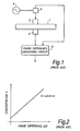
- FIG.1 shows a schematic block diagram of this type of microwave type concentration measuring apparatus. This is composed as follows. Microwave transmitting antenna 2 and microwave receiving antenna 3 are located on the wall of pipe 1 , which passes through the fluid under measurement. Microwaves from microwave generator 4 are inputted to microwave transmitting antenna 2 via power splitter 5 . The microwaves transmitted from microwave transmitting antenna 2 are diffused in the fluid under measurement inside pipe 1 , received by microwave receiving antenna 3 and inputted to phase difference measuring circuit 6 . At the same time, microwaves from microwave generator 4 are directly inputted to phase difference measuring circuit 6 via power splitter 5 .
- phase lag ⁇ 2 of the microwaves coming diffused by the fluid under measurement in pipe 1 behind the microwaves directly transmitted from microwave generator 4 via power splitter 5 is found by this phase difference measuring circuit 6 .
- this phase lag ⁇ 2 is compared with phase lag ⁇ 1 , which is that measured beforehand by filling pipe 1 with a reference fluid (for example, tap water, which can be regarded as zero concentration) and measuring the microwaves coming diffused by the reference fluid in the same state as the fluid under measurement.
- a is the gradient of the calibration curve
- the phase difference of the microwaves is measured, not the attenuation factor. Also, there is no need for any windows through which the microwaves are projected and received to be transparent. Therefore it is not easily affected by bubbles or dirt and, moreover, it is possible to continuously detect the concentration of the fluid under measurement.
- intercept b of the calibration curve 0.
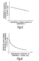
- measurement sensitivities of substances A, B and C as respective simple bodies are taken as (1/ a1 ), (1/ a2 ) and (1/ a3 )
- measurement sensitivity (1/ a0 ) of the mixture as a whole is determined by (1/ a1 ), (1/ a2 ) and (1/ a3 ) and the mixture proportions of substances A, B and C . Therefore, supposing that measurement sensitivity (1/ a3 ) varies due to variation of the constituent composition of substance C , measurement sensitivity (1/ a0 ) of the mixture as a whole will also vary. In this case, if correction is not carried out by taking the constituent composition of substance C at the time of a certain state as a reference, concentration measurement errors will occur.
- one object of the present invention is to provide a novel microwave type concentration measuring apparatus which has been devised in the light of the above facts and can always perform accurate concentration measurement.
- the above object of the present invention can be achieved by providing a microwave type concentration measuring apparatus having the following composition. That is to say, in a microwave type concentration measuring apparatus designed to find the concentration of mixture as a whole by finding the phase difference of the two phase lags from a first phase lag of microwaves which have been diffused by a reference liquid and a second phase lag of microwaves which have been diffused by a mixture prepared by mixing multiple substances and a liquid in constant proportions and using a calibration curve having a gradient corresponding to the mixture based on this phase difference, measuring the measurement sensitivity of an individual substance, of which the constituent composition varies, out of the multiple substances and, at the same time, setting the gradient of the calibration curve which corresponds to the mixture as a whole based on those measurement results.
- concentration measurement can be performed without undergoing any effect from that.
- the above object of the present invention can also be achieved by providing a microwave type concentration measuring apparatus having the following composition. That is to say, in the above-mentioned invention, providing a calibration curve gradient setting device that possesses a computing device which calculates the relationship of the calibration curve gradient for finding the concentration of a mixture composed of multiple substances with the measurement sensitivity of an individual substance of which the constituent composition varies; finding the calibration curve gradient by the computing device of the calibration curve gradient setting device based on the measurement result for the measurement sensitivity of the individual substance of which the constituent composition varies and setting this calibration curve gradient.
- the calibration curve gradient is updated every time a measurement result of the measurement sensitivity of the individual substance is inputted, and the most recent curve setting state is maintained.
- the above object of the present invention can also be achieved by providing a microwave type concentration measuring apparatus with the following composition. That is to say, in the above-mentioned invention, further providing a time lag setting device that inputs to the calibration curve gradient setting device by delaying for a specified time the measurement result for the measurement sensitivity of the individual substance of which the constituent composition varies.
- the above object of the present invention can also be achieved by providing a microwave type concentration measuring apparatus having the following composition. That is to say, in the said invention, further providing an averaging device which inputs to the calibration curve gradient setting device mean values of the measurement sensitivity of the individual substance of which the constituent composition varies.
- the mean value of the measurement sensitivity of the individual substance of which the constituent composition varies is used in setting the calibration curve gradient. Therefore, by performing the mixing of multiple substances in batch style, the concentration measurement of the whole of mixtures of types such as supplied to production processes batch by batch can be performed with good accuracy.
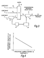
- FIG.3 shows the schematic composition of a microwave type concentration measuring apparatus in which the present invention is applied.
- This shows an example of the application of the present invention to a process for producing some product or other, taking a mixture of substances A, B and C in constant proportions suspended in water as the feedstock.
- the constituent (molecules and elements) compositions of substances A and B do not vary, but that the constituent composition of substance C does vary.
- this variation of the constituent composition of substance C has a great influence on the measurement sensitivity of the mixture of substances A, B and C as a whole. For example, this is a case where carbon is contained in substance C , the percentage content of that carbon varies, and that variation appears as a variation of the measurement sensitivity of the mixture as a whole.
- 11 is the substance mixing unit.
- Substance A supply pipe 12 which supplies substance A
- substance B supply pipe 13 which supplies substance B
- substance C supply pipe 14 which supplies substance C at a constant concentration
- water supply pipe 15 which supplies water
- the design is to prepare a mixture by mixing these substances A, B and C , which are supplied by substance A supply pipe 12 , substance B supply pipe 13 and substance C supply pipe 14 in constant proportions together with water, which is supplied from water supply pipe 15 .
- the design is to supply the mixture mixed in substance mixing unit 11 to a production process (not illustrated) as a feedstock via mixed fluid pipe 16 .
- Microwave type concentration meter 17 for sensitivity measurement, is mounted on substance C supply pipe 14 . Also, microwave type concentration meter 18 , for mixture concentration measurement, is mounted on mixture fluid pipe 16 .
- Sensitivity measuring microwave type concentration meter 17 measures the measurement sensitivity of substance C through substance C supply pipe 14 .
- reference fluid normally water
- Mixture fluid concentration measuring microwave type concentration meter 18 is connected to sensitivity measuring microwave type concentration meter 17 via time lag setter 19 and calibration curve gradient setter 20 .
- Time lag setter 19 finds in advance the time T that substance C , which has passed sensitivity measuring microwave type concentration meter 17 , will take to reach mixture fluid concentration measuring microwave type concentration meter 18 , having been mixed with the other substances A and B and water in substance mixer unit 11 and passed along mixture fluid pipe 16. It then sets this time T .
- calibration curve gradient setter 20 sets the calibration curve gradient of mixture concentration measuring microwave type concentration meter 18.
- Calibration curve gradient setter 20 is provided with a computing device that calculates the relationship between the measurement sensitivity of the single substance of which the constituent composition varies (here, substance C ) and the gradient of the calibration curve that finds the concentration of the mixture of substances A, B and C as a whole. It is designed to be able to find the gradient of the calibration curve using the computing device in response to input signals due to the measurement results of sensitivity measuring microwave type concentration meter 17 for substance C by itself, and to set this calibration curve gradient in mixture concentration measuring microwave type concentration meter 18 .
- substances A, B and C and water are supplied in set proportions to substance mixing unit 11 via substance A supply pipe 12 , substance B supply pipe 13 , substance C supply pipe 14 and water supply pipe 15 .
- substance C of which the constituent composition varies, is supplied in a state in which it is suspended in water at a constant concentration.
- a mixture is prepared by substance mixing unit 11 in which substances A, B and C and water are uniformly mixed. This mixture is supplied as feedstock to a production process (not illustrated) via mixed fluid supply pipe 16 .
- the calibration curve gradient corresponding to the inputted substance C measurement sensitivity is calculated by a computing device, based on the relational expression between the measurement sensitivity (1/ a3 ) of substance C and the calibration curve gradient ( a0 ) that finds the mixed substance concentration of substances A, B and C .
- This calibration curve gradient is then set in mixed substance concentration measuring microwave type concentration meter 18 .
- phase difference ⁇ ( ⁇ 2 - ⁇ 1 ) is found by mixture concentration measuring microwave type concentration meter 18 from phase lag ⁇ 2 of microwaves which are diffused in the mixture of substances A, B and C flowing in mixed fluid supply pipe 16 and pre-set and stored phase lag ⁇ 1 of a reference fluid (normally water).
- the measurement sensitivity of substance C by itself, of which the constituent composition varies, out of multiple substances A , B and C is measured by sensitivity measuring microwave type concentration meter 17 .
- This sensitivity measurement result is inputted to calibration curve gradient setter 20 , and the curve gradient is found by a computing device that possesses the relational expression between the measurement sensitivity of the single substance of which the constituent composition varies and the gradient of the calibration curve which finds the concentration of the mixture of substances A, B and C as a whole.
- This found calibration curve gradient is set in mixture concentration measuring microwave type concentration meter 18 .
- the gradient of the calibration curve of mixture concentration measuring microwave type concentration meter 18 is refreshed every time the result of measurement of the measurement sensitivity of substance C alone by sensitivity measuring microwave type concentration meter 17 is inputted by the computing device of calibration curve gradient setter 20 . Therefore, since the most recent gradient setting state is maintained, highly accurate concentration measurement can be continuously performed.
- the design is that the input to calibration curve gradient setter 20 of the measurement result of sensitivity measuring microwave type concentration meter 17 is delayed by time lag setter 19 by the time T until substance C that has passed sensitivity measuring microwave type concentration meter 17 is mixed with the other substances A and B and water in substance mixing unit 11 and reaches mixture concentration measuring microwave type concentration meter 18 by passing through mixed fluid supply pipe 16 .
- concentration of the mixture equivalent to a measurement time that uses a calibration curve gradient based on the result of the measurement time at sensitivity measuring microwave type concentration meter 17 can be measured by mixture concentration measuring microwave type concentration meter 18 . Therefore concentration measurement of a mixture as a whole can be performed with good accuracy in a system such as the continuous mixing of multiple substances.
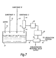
- FIG.7 shows the schematic composition of the second embodiment of the present invention. Parts which are identical to those in FIG.3 have been assigned like reference numerals.
- batch type mixing tank 31 is provided instead of substance mixing unit 11 .
- Substances A, B and C which are supplied by substance A supply pipe 12 , substance B supply pipe 13 and substance C supply pipe 14 together with water from water supply pipe 15 are supplied to mixing tank 31 in constant proportions. At the same time, it is designed to prepare 1 batch of mixture by mixing. Also, the design is that 1 batch of the mixture mixed in this mixing tank 31 is supplied as feedstock to a manufacturing process (not illustrated) via mixed fluid supply pipe 16 .
- Sensitivity measuring microwave type concentration meter 17 is mounted on substance C supply pipe 14 . Also, mixture concentration measuring microwave type concentration meter 18 is mounted on mixed fluid supply pipe 16 .
- Sensitivity measuring microwave type concentration meter 17 is connected to mixture concentration measuring microwave type concentration meter 18 via averaging circuit 32 and calibration curve gradient setter 20 .
- averaging circuit 32 calculates the measurement sensitivity of the whole of substance C that has passed through sensitivity measuring microwave type concentration meter 17 as a mean value for a certain time. It is designed to input this mean value to calibration curve gradient setter 20 . Also, calibration curve gradient setter 20 sets the calibration curve gradient of mixture concentration measuring microwave type concentration meter 18 . Calibration curve gradient setter 20 is provided with a computing device that calculates the relationship between the measurement sensitivity of the single substance of which the constituent composition varies (here, substance C ) and the gradient of the calibration curve that finds the concentration of the mixture of substances A, B and C as a whole.
- the computing device finds the gradient of the calibration curve corresponding to the mean value of the measurement sensitivity of the whole of substance C that has passed through sensitivity measuring microwave type concentration meter 17 . It is designed to set the obtained calibration curve gradient in mixture concentration measuring microwave type concentration meter 18 .
- one batch of mixture is prepared by supplying substances A, B and C , which are supplied through substance A supply pipe 12 , substance B supply pipe 13 and substance C supply pipe 14 , together with water supplied from water supply pipe 15 , to batch type mixing tank 31 in constant proportions and, at the same time mixing them. After that, the mixture is supplied as feedstock to a manufacturing process (not illustrated) via mixture fluid supply pipe 16 .
- the mean value of the measurement sensitivity of the whole of substance C that has passed through sensitivity measuring microwave type concentration meter 17 is calculated by averaging circuit 32 , and that mean value is inputted to calibration curve gradient setter 20 .
- a calibration curve gradient is found corresponding to the mean value of the measurement sensitivity of the whole of substance C from averaging circuit 32 .
- the same effect can be expected as with Embodiment 1 described above.
- the mean value over a certain time of the measurement sensitivity of a single substance of which the constituent composition varies is found by averaging circuit 32 .
- the design is that the calibration curve gradient is set by calibration curve gradient setter 20 based on this mean value. Therefore the concentration measurement of the overall mixture in a manufacturing process that performs batch type mixing of multiple substances and supplies feedstock batch by batch to the manufacturing process can be performed with good accuracy.
- the concentration of a mixture equivalent to this measurement time can be measured. Therefore, overall concentration measurement of a mixture with a system such as continuously mixing multiple substances can be performed with good accuracy.
- the mean value of the measurement sensitivity of a single substance of which the constituent composition varies is used in the setting of the calibration curve gradient. Therefore, by performing the mixing of multiple substances by the batch method, the overall concentration measurement of a mixture can be performed with good accuracy in a system such as supplying to a manufacturing process batch by batch.
Landscapes
- Physics & Mathematics (AREA)
- Electromagnetism (AREA)
- Health & Medical Sciences (AREA)
- Life Sciences & Earth Sciences (AREA)
- Chemical & Material Sciences (AREA)
- Analytical Chemistry (AREA)
- Biochemistry (AREA)
- General Health & Medical Sciences (AREA)
- General Physics & Mathematics (AREA)
- Immunology (AREA)
- Pathology (AREA)
- Investigating Or Analysing Materials By Optical Means (AREA)
Claims (4)
- Dispositif de mesure de la concentration conçu pour déterminer la concentration totale d'un corps fluide mélangé en déterminant la différence de phase entre un premier signal micro-onde qui a été diffusé par un liquide témoin et un deuxième signal micro-onde qui a été diffusé par un mélange préparé en mélangeant de multiples substances et un liquide dans des proportions constantes, en utilisant une courbe d'étalonnage ayant un gradient correspondant au mélange sur la base de la différence de phase, le dispositif comprenant :un dispositif de fixation du gradient de la courbe d'étalonnage, qui mesure la sensibilité à la mesure d'une substance unique, dont la composition des constituants varie, parmi lesdites multiples substances et qui, en même temps, fixe un gradient de la courbe d'étalonnage, qui correspond au mélange dans son entier sur la base du résultat de la mesure.
- Dispositif suivant la revendication 1, comprenant :un dispositif de fixation du gradient d'une courbe d'étalonnage comprenant des moyens de calcul de la relation entre le gradient de la courbe d'étalonnage pour trouver une concentration d'un mélange composé de multiples substances et la sensibilité à la mesure d'une substance individuelle, dont la composition des constituants varie ;le gradient de la courbe d'étalonnage est trouvé en utilisant le dispositif de calcul du dispositif de fixation du gradient de la courbe d'étalonnage sur la base du résultat de mesure de la sensibilité à la mesure de la substance individuelle, dont la composition des constituants varie ; etle gradient de la courbe d'étalonnage est fixé.
- Dispositif de mesure de la concentration du type à micro-onde suivant la revendication 2, comprenant :un dispositif de fixation d'un retard de temps qui envoie un signal d'entrée au dispositif de fixation d'un gradient de courbe d'étalonnage en retardant pendant une durée précisée le résultat de la mesure de la sensibilité à la mesure de la substance individuelle, dont la composition des constituants varie.
- Dispositif de mesure de la concentration de type à micro-onde suivant la revendication 2, comprenant :un dispositif pour faire une moyenne qui envoie en entrée au dispositif de fixation d'un gradient de courbe d'étalonnage une valeur moyenne de la sensibilité à la mesure de la substance individuelle, dont la composition des constituants varie.
Applications Claiming Priority (3)
| Application Number | Priority Date | Filing Date | Title |
|---|---|---|---|
| JP24692397A JP3413073B2 (ja) | 1997-09-11 | 1997-09-11 | マイクロ波式濃度測定装置 |
| JP246923/97 | 1997-09-11 | ||
| JP24692397 | 1997-09-11 |
Publications (3)
| Publication Number | Publication Date |
|---|---|
| EP0902276A2 EP0902276A2 (fr) | 1999-03-17 |
| EP0902276A3 EP0902276A3 (fr) | 2003-04-16 |
| EP0902276B1 true EP0902276B1 (fr) | 2005-12-14 |
Family
ID=17155775
Family Applications (1)
| Application Number | Title | Priority Date | Filing Date |
|---|---|---|---|
| EP98307379A Expired - Lifetime EP0902276B1 (fr) | 1997-09-11 | 1998-09-11 | Dispositif de mesure de la concentration par micro-ondes |
Country Status (5)
| Country | Link |
|---|---|
| US (1) | US6239600B1 (fr) |
| EP (1) | EP0902276B1 (fr) |
| JP (1) | JP3413073B2 (fr) |
| CA (1) | CA2246958C (fr) |
| DE (1) | DE69832765T2 (fr) |
Families Citing this family (14)
| Publication number | Priority date | Publication date | Assignee | Title |
|---|---|---|---|---|
| EP1102041A1 (fr) | 1999-11-20 | 2001-05-23 | Reto T. Meili | Procédé de mesure et système pour la mise en oeuvre du procédé |
| DE10002597A1 (de) * | 2000-01-21 | 2001-08-02 | Infineon Technologies Ag | Verfahren und Vorrichtung zur Identifikation von in einer Trägerflüssigkeit vorhandenen Molekülen |
| AUPS059002A0 (en) * | 2002-02-15 | 2002-03-14 | Airservices Australia | Determination of solution concentration |
| RU2275620C2 (ru) * | 2004-03-30 | 2006-04-27 | Михаил Вениаминович Жиров | Устройство для измерения физических свойств жидкости |
| WO2005106464A1 (fr) | 2004-04-26 | 2005-11-10 | The Procter & Gamble Company | Procedes pour estimer les caracteristiques de substrats fibreux et pour traiter des substrats fibreux |
| RU2285913C1 (ru) * | 2005-02-28 | 2006-10-20 | Федеральное государственное образовательное учреждение высшего профессионального образования Мурманский государственный технический университет | Устройство для измерения физических свойств жидкости |
| CN101484797A (zh) | 2006-06-30 | 2009-07-15 | 宝洁公司 | 用于测量微带定向耦合器的覆盖层(例如毛发)中的水分的装置 |
| US20080202991A1 (en) * | 2007-02-27 | 2008-08-28 | Meagher James E | Apparatus and method for chemical addition to slurry |
| RU2534747C1 (ru) * | 2013-12-13 | 2014-12-10 | Федеральное государственное учреждение науки Институт проблем управления им. В.А. Трапезникова РАН | Устройство для измерения физических свойств жидкости в емкости |
| US9255827B2 (en) * | 2013-12-17 | 2016-02-09 | International Business Machines Corporation | Computer based fluid flow velocity estimation from concentrations of a reacting constituent for products and services |
| US11047722B2 (en) * | 2013-12-17 | 2021-06-29 | International Business Machines Corporation | Computer based fluid flow velocity estimation from concentrations of a reacting constituent for products and services |
| RU2631340C1 (ru) * | 2016-08-29 | 2017-09-21 | Федеральное государственное бюджетное учреждение науки Институт радиотехники и электроники им. В.А. Котельникова Российской академии наук | Свч-способ измерения концентрации водных растворов |
| DE102019210303B3 (de) * | 2019-07-11 | 2021-01-14 | Berthold Technologies Gmbh & Co. Kg | Mikrowellenbasiertes Messgerät |
| CN112730464A (zh) * | 2020-12-31 | 2021-04-30 | 北京城市排水集团有限责任公司 | 污泥浓度在线测量方法、装置、电子设备及介质 |
Family Cites Families (10)
| Publication number | Priority date | Publication date | Assignee | Title |
|---|---|---|---|---|
| US4962384A (en) * | 1986-03-06 | 1990-10-09 | Walker Charles W E | Microwave antenna apparatus |
| US4764718A (en) * | 1986-04-23 | 1988-08-16 | Chevron Research Company | Microwave oil saturation scanner |
| JP3139874B2 (ja) * | 1993-03-30 | 2001-03-05 | 株式会社東芝 | 濃度計 |
| JP3160428B2 (ja) | 1993-07-12 | 2001-04-25 | 株式会社東芝 | 濃度計 |
| US5470595A (en) * | 1994-02-22 | 1995-11-28 | Kraft General Foods R&D, Inc. | Method and system for processing cheese |
| JP3160474B2 (ja) | 1994-09-12 | 2001-04-25 | 株式会社東芝 | マイクロ波濃度計 |
| DK171153B1 (da) * | 1995-02-10 | 1996-07-01 | Slagteriernes Forskningsinst | Fremgangsmåde og anlæg ved blanding af et uensartet, strømningsdygtigt fødevare-, foder- eller farmaceutisk materiale samt indretning til udtagelse afprøver |
| GB2304477B (en) * | 1995-08-16 | 1997-10-01 | Hydronix Ltd | Signal processing method and apparatus |
| JP3160520B2 (ja) * | 1996-01-31 | 2001-04-25 | 株式会社東芝 | 濃度計 |
| JP3311230B2 (ja) * | 1996-03-11 | 2002-08-05 | 株式会社東芝 | マイクロ波式濃度計 |
-
1997
- 1997-09-11 JP JP24692397A patent/JP3413073B2/ja not_active Expired - Fee Related
-
1998
- 1998-09-10 US US09/150,699 patent/US6239600B1/en not_active Expired - Lifetime
- 1998-09-10 CA CA002246958A patent/CA2246958C/fr not_active Expired - Fee Related
- 1998-09-11 EP EP98307379A patent/EP0902276B1/fr not_active Expired - Lifetime
- 1998-09-11 DE DE69832765T patent/DE69832765T2/de not_active Expired - Lifetime
Also Published As
| Publication number | Publication date |
|---|---|
| CA2246958C (fr) | 2003-11-25 |
| JP3413073B2 (ja) | 2003-06-03 |
| DE69832765D1 (de) | 2006-01-19 |
| EP0902276A2 (fr) | 1999-03-17 |
| JPH1183761A (ja) | 1999-03-26 |
| EP0902276A3 (fr) | 2003-04-16 |
| US6239600B1 (en) | 2001-05-29 |
| DE69832765T2 (de) | 2006-11-02 |
| CA2246958A1 (fr) | 1999-03-11 |
Similar Documents
| Publication | Publication Date | Title |
|---|---|---|
| EP0902276B1 (fr) | Dispositif de mesure de la concentration par micro-ondes | |
| JP3160428B2 (ja) | 濃度計 | |
| US4701705A (en) | NMR moisture measurements | |
| US5260667A (en) | Method and apparatus for determining the percentage water condent of oil in water emulsion by specific admittance measurement | |
| FI80961B (fi) | Saett och anordning foer nivaomaetning med mikrovaogor. | |
| AU6307496A (en) | Method for correcting a liquid dispensing error, and a liquiddispensing device | |
| US3892127A (en) | Oil detection system | |
| US5864240A (en) | Method and apparatus for measuring concentration of matter in liquid by using microwaves | |
| FI61246C (fi) | Saett och anordning foer beraekning av en vaetskeytas nivao | |
| KR100320329B1 (ko) | 마이크로파를이용한농도계 | |
| Baird et al. | Comparison of the hole pressure and exit pressure methods for measuring polymer melt normal stresses | |
| JPH04238246A (ja) | 濃度計 | |
| EP1102069A2 (fr) | Analyseur par injection de flux et méthode d'analyse | |
| JP2001056282A (ja) | 粒径分布測定装置 | |
| Rogez et al. | Ultrasonic velocity dispersion in liquids between 3.3 and 330 MHz using a high resolution phase measurement technique | |
| RU2178871C1 (ru) | Массовый расходомер газожидкостного потока | |
| JPS595857B2 (ja) | 油分濃度測定装置 | |
| JPH1183759A (ja) | 濃度測定方法および装置 | |
| SU1195292A1 (ru) | Способ определения концентрации растворов | |
| JPH02212750A (ja) | 水蒸気量測定装置 | |
| SU1682794A1 (ru) | Способ измерени расхода газа | |
| FI58215C (fi) | Foerfarande foer bestaemning av den genomsnittliga partikelstorleken i en uppslamning samt analysator foer utfoerande av foerfarandet | |
| JPH03163350A (ja) | Bodの測定方法及びその装置 | |
| JP2001242099A (ja) | マイクロ波式濃度計 | |
| SU593172A1 (ru) | Способ приготовлени газовых смесей дл проверки приборов контрол загр знени атмосферы |
Legal Events
| Date | Code | Title | Description |
|---|---|---|---|
| PUAI | Public reference made under article 153(3) epc to a published international application that has entered the european phase |
Free format text: ORIGINAL CODE: 0009012 |
|
| 17P | Request for examination filed |
Effective date: 19981007 |
|
| AK | Designated contracting states |
Kind code of ref document: A2 Designated state(s): AT BE CH CY DE DK ES FI FR GB GR IE IT LI LU MC NL PT SE |
|
| AX | Request for extension of the european patent |
Free format text: AL;LT;LV;MK;RO;SI |
|
| PUAL | Search report despatched |
Free format text: ORIGINAL CODE: 0009013 |
|
| AK | Designated contracting states |
Designated state(s): AT BE CH CY DE DK ES FI FR GB GR IE IT LI LU MC NL PT SE |
|
| AX | Request for extension of the european patent |
Extension state: AL LT LV MK RO SI |
|
| RIC1 | Information provided on ipc code assigned before grant |
Ipc: 7G 01N 33/34 B Ipc: 7G 05D 11/08 B Ipc: 7B 01F 15/04 B Ipc: 7G 01N 22/00 A |
|
| AKX | Designation fees paid |
Designated state(s): DE FR GB |
|
| GRAP | Despatch of communication of intention to grant a patent |
Free format text: ORIGINAL CODE: EPIDOSNIGR1 |
|
| GRAS | Grant fee paid |
Free format text: ORIGINAL CODE: EPIDOSNIGR3 |
|
| GRAA | (expected) grant |
Free format text: ORIGINAL CODE: 0009210 |
|
| AK | Designated contracting states |
Kind code of ref document: B1 Designated state(s): DE FR GB |
|
| REG | Reference to a national code |
Ref country code: GB Ref legal event code: FG4D |
|
| REF | Corresponds to: |
Ref document number: 69832765 Country of ref document: DE Date of ref document: 20060119 Kind code of ref document: P |
|
| ET | Fr: translation filed | ||
| PLBE | No opposition filed within time limit |
Free format text: ORIGINAL CODE: 0009261 |
|
| STAA | Information on the status of an ep patent application or granted ep patent |
Free format text: STATUS: NO OPPOSITION FILED WITHIN TIME LIMIT |
|
| 26N | No opposition filed |
Effective date: 20060915 |
|
| PGFP | Annual fee paid to national office [announced via postgrant information from national office to epo] |
Ref country code: GB Payment date: 20090909 Year of fee payment: 12 |
|
| PGFP | Annual fee paid to national office [announced via postgrant information from national office to epo] |
Ref country code: DE Payment date: 20090903 Year of fee payment: 12 |
|
| PGFP | Annual fee paid to national office [announced via postgrant information from national office to epo] |
Ref country code: FR Payment date: 20091012 Year of fee payment: 12 |
|
| GBPC | Gb: european patent ceased through non-payment of renewal fee |
Effective date: 20100911 |
|
| REG | Reference to a national code |
Ref country code: FR Ref legal event code: ST Effective date: 20110531 |
|
| REG | Reference to a national code |
Ref country code: DE Ref legal event code: R119 Ref document number: 69832765 Country of ref document: DE Effective date: 20110401 |
|
| PG25 | Lapsed in a contracting state [announced via postgrant information from national office to epo] |
Ref country code: DE Free format text: LAPSE BECAUSE OF NON-PAYMENT OF DUE FEES Effective date: 20110401 Ref country code: FR Free format text: LAPSE BECAUSE OF NON-PAYMENT OF DUE FEES Effective date: 20100930 |
|
| PG25 | Lapsed in a contracting state [announced via postgrant information from national office to epo] |
Ref country code: GB Free format text: LAPSE BECAUSE OF NON-PAYMENT OF DUE FEES Effective date: 20100911 |