EP0902270B1 - Polarimetrische Probenzelle und Polarimeter - Google Patents
Polarimetrische Probenzelle und Polarimeter Download PDFInfo
- Publication number
- EP0902270B1 EP0902270B1 EP98116995A EP98116995A EP0902270B1 EP 0902270 B1 EP0902270 B1 EP 0902270B1 EP 98116995 A EP98116995 A EP 98116995A EP 98116995 A EP98116995 A EP 98116995A EP 0902270 B1 EP0902270 B1 EP 0902270B1
- Authority
- EP
- European Patent Office
- Prior art keywords
- cavity
- sample cell
- specimen
- channel
- polarimetry
- Prior art date
- Legal status (The legal status is an assumption and is not a legal conclusion. Google has not performed a legal analysis and makes no representation as to the accuracy of the status listed.)
- Expired - Lifetime
Links
Images

Classifications
-
- G—PHYSICS
- G01—MEASURING; TESTING
- G01N—INVESTIGATING OR ANALYSING MATERIALS BY DETERMINING THEIR CHEMICAL OR PHYSICAL PROPERTIES
- G01N21/00—Investigating or analysing materials by the use of optical means, i.e. using sub-millimetre waves, infrared, visible or ultraviolet light
- G01N21/17—Systems in which incident light is modified in accordance with the properties of the material investigated
- G01N21/21—Polarisation-affecting properties
Definitions
- the present invention generally relates to polarimetry (measurement on optical activity of specimen, expressed in angle of rotation), and more particularly to an improvement in a sample cell for accommodating a liquid specimen subjected to the polarimetry.
- One of the conventional methods of examining sugar or protein in a urine includes a use of a test paper impregnated with a reagent.
- the test paper is dipped in the urine and a color reaction thereof is observed by a spectrophotometer or the like.
- expendable supplies such as test papers are required.
- Glucose and albumin in the urine demonstrate optical activities but the other components in the urine do not demonstrate the optical activity.
- the above publication proposes derivations of the urine sugar value and urine protein value by the polarimetry on the urine. According to this method, even if the glucose or the albumin contained in the urine is small, it is possible to determine the urine sugar value or urine protein value without using any expendable supplies.
- the rotated angle of the plane of vibration i.e., the angle of rotation, is directly derived by projecting a light having a particular plane of vibration on a specimen to be detected and detecting a plane of vibration of the light transmitted through the specimen by using a rotary analyzer.
- An analyzer rotator 85 is for rotating the transmission axis of the analyzer 84 in a plane perpendicular to the direction of the advance of the light.
- An photosensor 86 is for detecting the light transmitted through the analyzer 84.
- the computer 87 controls the analyzer rotator 85 while recording and analyzing an output signal from the photosensor 86.
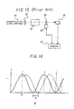
- the abscissa represents the relative angle " ⁇ " formed between the light transmission axis of the polarizer 82 and the light transmission axis of the analyzer 84
- the ordinate represents an intensity "I" of the light that has reached the photosensor 86, i.e., the output signal of the photosensor 86.
- the solid line indicates the output signal in the case where the specimen to be determined demonstrates no optical activity.
- the extinction point of the specimen which demonstrates an optical activity displaces by " ⁇ " as compared with that of the specimen which does not demonstrate the optical activity. It is therefore possible to measure the angle of rotation by finding the displacement of the extinction point by the computer 87.
- S/N ratio in the output signal of the photosensor 86 is however comparatively inferior and it is difficult to accurately determine the position of the extinction point. As a result, it is difficult to measure the specimen having a small angle of rotation with high accuracy.
- V varies with a medium, wavelength of light or temperature.
- the optical Faraday modulator includes, for instance, a rod of flint glass and a solenoid coil configured around the rod.
- a current is flown through the solenoid coil for generating a magnetic field inside the rod while permitting a light to transmit through the rod along an axis of the rod, the plane of vibration of the light propagating inside the rod rotates.
- the intensity of the current flown through the solenoid coil it is possible to vary the angle of rotation of the plane of vibration at will.
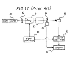
- FIG. 17 An example of the polarimeter which employs the optical Faraday modulator is shown in FIG. 17.
- parts and components which are identical with those used in the polarimeter shown in FIG. 15 are tagged with the same reference numerals.
- the optical Faraday modulator 88 vibrates the plane of vibration of a light transmitted through a polarizer 82 by a modulation signal from a signal generator 89.
- a lock-in amplifier 90 is for phase sensitive detection of an output signal from the photosensor 86 with reference to the vibration-modulated signal from the optical Faraday modulator 88.
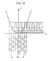
- FIG. 18 shows the abscissa and the ordinate represent " ⁇ " and the output signal "I" of the photosensor, respectively.
- FIG. 18 shows the extinction point and the neighborhood thereof in an enlarged view.
- I T ⁇ I o ⁇ ⁇ cos [ ⁇ - ⁇ + ⁇ ⁇ sin ( ⁇ ⁇ t)] ⁇ 2 where, "t” is time.
- a sample cell for accommodating the specimen used in the above-mentioned polarimeter has a pair of transparent light-transmitting windows which permit the light to transmit through the inside thereof.
- the sample cells have been configured, for instance, in a box made of glass with its top end open. Liquid specimens are introduced into the cells through the top open end by the use of a pipette, a syringe and the like.
- the measurement is performed for every sample cells and the replacement of the specimen is also performed for every sample cells. Namely, the measurement is performed after introducing the specimen into the sample cell and arranging the sample cell in an optical system. The specimen is therefore required to be replaced together with the sample cell. Further, for using the sample cell again, it is required to exhaust the specimen from the sample cell taken out from the optical system and to wash the sample cell. As described previously, the conventional polarimetry consumes much man power.
- An object of the present invention is to provide a sample cell for polarimetry which permits easy replacement of the liquid specimen.
- Another object of the present invention is to provide a sample cell and a polarimeter comprising such sample cell capable of preventing mixing of bubbles into the liquid specimen and performing the polarimetry with high accuracy.
- a tubular sample cell of substantially sealed-type having a cavity is used instead of a box-type sample cell which has been used in the conventional polarimeter. Both the end faces of the cavity is sealed with a light-transmitting material and the specimen is contained in the cavity. A coil is provided around the sample cell for generating a magnetic field inside the cavity.
- an optical Faraday effect attributable to the specimen itself is also brought in the case of applying the magnetic field to the specimen accommodated in the cell, for rotating the plane of vibration of the light transmitting through the inside of the cell.
- optical Faraday effect can be obtained also in the cases of using water, chloroform, acetone and the like which are widely used as the medium.
- Verdet's constants V of the typical media are shown in TABLE 1. In the cases of any media, the Verdet's constant V varies with the kind of the medium, the wavelength of light and the temperature.
- Such sample cell uses a base member configured by cutting a block of a non-magnetic material such as aluminum.
- an inlet channel for introducing the specimen into the sample cell an outlet channel for exhausting the specimen from the sample cell and a vent hole are provided on the sample cell, it is possible to perform a replacement of the specimen and washing of the inside of the cell without detaching the sample cell from the optical system.
- the contamination is attributable to a substance which does not demonstrate an optical activity, the contamination corresponds to a substantial decrease in the value "T” in the equation (2) and makes the position of the extinct point unclear. Due to this fact, the accuracy of the measurement value is deteriorated. In this case, a ratio of the variance in the value "I” to the variance in the value " ⁇ ” in the equation (3), or a ratio of the value "S” to the value " ⁇ ” in the equation (9) becomes small. It is therefore possible to derive a value due to the contamination by measuring a reference specimen whose "T” is known and taking the obtained decrease in the value into account. When the value due to the contamination exceeds a certain value, washing or replacement of the sample cell may well be instructed. In the process, it is not imperative to use the reference specimen and the value due to the contamination may alternatively be derived from a result of a measurement conducted by the use of a specimen whose minimum value of "T" is known.
- the position of the extinction point i.e., the obtained angle of rotation
- the value "I ⁇ " in the equation (3) and the value "S” in the equation (9) also vary.
- the displacement is an angle of rotation due to the contamination substance and may simply be added to the angle of rotation attributable to the specimen to be determined. For this reason, when a measurement has previously been conducted on a reference specimen whose angle of rotation is known, and a correction is made on the measurement value of the specimen to be determined by the difference between the previous measurement value and the known angle of rotation, it is possible to ignore an error produced by the contamination substance.
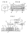
- FIG. 1A and FIG. 1B show a sample cell not forming part of the invention.
- the sample cell 1 is obtained in the following manner.
- a base member 2 is obtained by cutting a rectangular solid aluminum block.
- a solenoid coil 5 By winding an enameled wire with a diameter of 0.7 mm around the cylindrical part cut between the flanges 2a and 2b of the base member 2 for 600 turns, a solenoid coil 5 with a length of 35 mm is formed.
- the solenoid coil 5 is for applying a magnetic field to the specimen accommodated in the cavity 3.
- Threaded holes 6a and 6b are provided on the flanges 2a and 2b, respectively for fixing the sample cell 1 on a polarimeter.
- the diameter of the threaded holes 6a and 6b is 3 mm and the depth thereof is 5 mm. Only after providing the flanges 2a and 2b on the base member 2, provision of these threaded holes 6a and 6b becomes possible. With this measure, installation of the sample cell 1 on the polarimeter becomes easy.
- a semiconductor laser projector module 8 projects a semiconductor laser with a wavelength of 780 nm of an elliptical cross section with a long diameter of about 4 mm and a short diameter of about 2 mm in a substantial parallel ray as indicated by the dashed line in the figure.
- the semiconductor laser projector module 8 also contains a driving circuit for the semiconductor laser which permits the semiconductor laser to oscillate continuously.
- a polarizer 9 transmits only such specified polarized component of the projected semiconductor laser that has a plane of vibration which is, for instance, parallel to the plane of this paper.
- An analyzer 10 is arranged so as to transmits only such a polarized component of the light transmitted through the sample cell 1 that is perpendicular to the axis of transmission of the polarizer 9.
- the photosensor 11 detects the light transmitted through the analyzer 10. All of these components are fixed on a rail-shaped base plate 7 having a length of 150 mm.
- a current source 12 can supply a sweep current of from -5 A to +5 A to the solenoid coil 5 on an instruction signal from a computer 13.
- the computer 13 also records and analyzes an output signal from a lock-in amplifier 15.
- a signal generator 14 supplies a modulation signal to the current source 12 for modulating the current to be supplied to the solenoid coil 5 of the sample cell 1.
- the current source 12 interposes the modulation current due to the modulation signal in the sweep current instructed by the computer 13, and supplies the interposed current to the solenoid coil 5.
- FIG. 3 shows the output signal of the lock-in amplifier 15, when the current to be supplied to the coil 5 is swept in a range between -1.5 A and +1.5 A.
- the abscissa indicates the current "J" to be supplied to the coil 5 and the ordinate represents the output signal (arbitrary value) of the lock-in amplifier 15.
- the solid line “a” represents the case wherein pure water which does not demonstrate an optical activity is measured as the specimen.
- "J” equals to zero i.e., any magnetic field is not applied to the pure water as the specimen, an extinction point appears.
- the plane of vibration of the light rotates due to the optical Faraday effect and the output signal "S" of the lock-in amplifier 15 varies as in the case of varying ⁇ in the equation (6) i.e., of rotating the analyzer 10.
- the dashed line “b" in FIG. 3 indicates the case of using a sucrose aqueous solution with a concentration of 250 mg/dl at 20°C as the specimen.
- the dashed line “b” coincides to a straight line obtained by parallelly shifting the solid line "a” along the abscissa by +1.21 A. The width of this shift of the extinction point corresponds to the angle of rotation due to the specimen.
- the angles of rotation are additionally measured at 20°C by using sucrose aqueous solutions with concentrations of 50, 100, 150 and 250 mg/dl, respectively.
- the results thereof are shown in FIG. 4.
- the abscissa represents the concentration of the sucrose and the ordinate represents the current "J" for reaching the extinction point. As seen from FIG. 4, it is recognized that the one is proportional to the other.
- the angle of rotation can also be calculated, even in another case where no extinction point exists in the range of sweeping, by extrapolating the characteristic in the range, because the output signal "S" of the lock-in amplifier 15 varies linearly with respect to the magnetic field i.e., the current "J", as illustrated by FIG. 3 and indicated by the equation (9).
- the angle of rotation can instead be calculated by interpolating or extrapolating the results of the measurements on at least two points. By this procedure, it is also possible to shorten the time for conducting the measurement.
- the specimen is introduced into the cavity 3 through the inlet/outlet channel 23.
- air inside the sample cell 22 is expelled therefrom through the inlet/outlet channel 23 to the outside.
- the inlet/outlet channel 23 is formed above the optical path, no air remains in the optical path of light after the introduction of the specimen. Therefore, an accurate measurement is made possible.
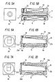
- a cylindrical part with a diameter of 17 mm is formed on the center thereof, while leaving untouched parts with a width of 10 mm on its both ends, respectively, thereby to form flanges 25a and 25b.
- a cavity 26 having a rectangular cross-section is formed between the both end faces.
- the cross-section of one open end of the cavity 26 is a rectangle of 8 mm x 13 mm and the cross-section of the other open end is a square of 8 mm x 8 mm.
- the top face of the cavity 26 has an inclination of about 5.7 degrees (tan-1 (5/50) ) between the both open ends.
- a circular hole with a diameter of 22 mm and a depth of 2.5 mm is provided, and a glass plate 27a with a diameter of 22 mm and a thickness of 2.5 mm is tightly fitted into the hole.
- a circular hole with a diameter of 12 mm and a depth of 2.5 mm is provided, and a glass plate 27b with a diameter of 12 mm and a thickness of 2.5 mm is tightly fitted into the hole.
- an inlet/outlet channel 28 having a circular cross section with a diameter of 6 mm is provided.
- the specimen is introduced into the cavity 26 through the inlet/outlet channel 28.
- air inside the cavity 26 is expelled therefrom through the inlet/outlet channel 28 to the outside.
- the inlet/outlet channel 28 is provided above an optical path, no air remains in the optical path after the introduction of the specimen.
- FIG. 7A A sample cell in accordance with another embodiment of the invention is shown by FIG. 7A and FIG. 7B.
- the sample cell 30 has a structure similar to the sample cell 24 used in EXAMPLE 3. However, the sample cell 30 has a vent hole 31 having a circular cross-section with a diameter of 1.0 mm provided on the uppermost part i.e., the wider open end side of the inclined top face of the cavity 26 for communicating the inside with the outside, instead of the inlet/outlet channel 28. On the bottom face at the narrower open end side i.e., the undermost part of the cavity 26, an inlet/outlet channel 32 of a circular cross-section with a diameter of 2.5 mm is arranged. The specimen is introduced into the cavity 26 through the inlet/outlet channel 32. At the introduction, air inside the cavity 26 is expelled therefrom through the vent hole 31.
- the specimen is expelled therefrom through the inlet/outlet channel 32.
- air flows into the cavity 26 through the vent hole 31.
- water or a cleaning solution is introduced and expelled through the inlet/outlet channel 32.
- the inlet/outlet channel 32 at the undermost part of the cavity 26
- the expelling of the specimen becomes more easy as compared with the sample cell 24 of EXAMPLE 3.
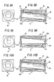
- a cylindrical part with a diameter of 17 mm is formed on the center thereof, while leaving untouched parts with a the width of 10 mm on the both ends, thereby to form flanges 35a and 35b.
- a cylindrical cavity 36 having a diameter of 12 mm and an axis inclined by about 5.7 degrees (tan -1 (5/50)) with respect to the axis of the cylindrical part is provided between the both end faces.
- holes with a diameter of 22 mm and a depth of 2.5 mm are provided, and glass plates 37a and 37b with a diameter of 22 mm and a thickness of 2.5 mm are tightly fitted into the holes, respectively.
- the cavity 36 has a length i.e., length of the optical path of 50 mm and can contain the specimen of about 5.7 cc.
- FIG. 9A and FIG. 9B A sample cell in accordance with a further embodiment of the invention is shown by FIG. 9A and FIG. 9B.
- the sample cell 41 has a structure similar to the sample cell 24 used in EXAMPLE 3.
- the sample cell 41 however has an outlet/vent hole 42 of a circular cross-section with a diameter of 2.5 mm provided, instead of the inlet/outlet channel 28.
- an inlet channel 43 of a circular cross-section with a diameter of 2.5 mm is provided at the narrower open end side of the bottom face of the cavity 26, at the narrower open end side of the bottom face of the cavity 26, an inlet channel 43 of a circular cross-section with a diameter of 2.5 mm is provided.
- the sample cell 45 has a structure similar to the sample cell 34 used in Embodiment 5. However, the sample cell 45 has an inlet/vent hole 46 of a circular cross-section with a diameter of 2.5 mm provided, instead of the vent hole 38. An outlet channel 47 having a similar configuration to that of the inlet/outlet channel 39 is used exclusively for expelling the specimen from the cavity 36. The specimen is introduced into the cavity through the inlet/vent hole 46.
- both the specimens are rendered hardly liable to mix with each other, and the replacement of the specimen in the cavity becomes easy. For the same reason, the washing of the cavity is made easy.
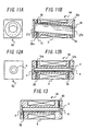
- FIG. 11A and FIG. 11B A sample cell in accordance with a further embodiment of the invention is shown by FIG. 11A and FIG. 11B.
- the sample cell 49 has a structure similar to the sample cell 34 used in EXAMPLE 5. However, the sample cell 49 has an inlet channel 51 is additionally provided on the bottom of the cavity 36 at a position opposite to the vent hole 38. In addition, an outlet channel 50 having a similar configuration to that of the inlet/outlet channel 39 is used exclusively for expelling the specimen.
- a specimen to be examined is supplied to the cavity 36 through the inlet channel 51. Air inside the cavity 36 is expelled therefrom through the vent hole 38. As shown, by the virtue of inclining the axis of the cylindrical cavity 36, even in a case of involving the bubbles in the cavity 36, the bubbles do not interfere with the transmitting light because the bubbles move along the wall of the cavity 36.
- the inlet channel 51 on the bottom, it is possible to suppress a mixing of the air inside the cavity 36 with the specimen at the time of introducing the specimen , and to greatly reduce the bubbling.
- the specimen in the cavity 36 is expelled therefrom through the outlet channel 50.
- air is flown into the cavity 36 through the vent hole 38.
- the expelling is easy.
- a fresh specimen is introduced into the cavity 36 through the inlet channel 51, and the examined specimen which had previously been introduced into the cavity 36 is expelled through the outlet channel 50 by being pushed out.
- water or a cleaning solution is introduced therein through the inlet channel 51 and expelled therefrom through the outlet channel 50.
- FIG. 12A and FIG. 12B A sample cell in accordance with an embodiment not forming part of the present invention is shown by FIG. 12A and FIG. 12B.
- the sample cell 53 has the same structure as that used in EXAMPLE 1. However, a vent hole 54a having a circular cross-section with a diameter of 1.0 mm is provided on the top of the cavity 3 at the one open end side. On the top of the cavity 3 at the other open end side, another vent hole 54b is provided. In addition, on the bottom of the cavity at its both open ends side, an inlet channel 55 having a circular cross-section with a diameter of 2.5 mm and an outlet channel 56 having a circular cross-section with a diameter of 2.5 mm are provided, respectively.
- the sample cell 34 of Embodiment 5 shown in FIG. 8A and FIG. 8B requires a larger diameter of the cylindrical cavity 36 for securing an equivalent optical path length as that of the sample cell 1 shown in FIG. 1A and FIG. 1B.
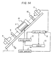
- the sample cell 61 shown in FIG. 13 has a structure similar to the sample cell 1 of EXAMPLE 1.
- an inlet/outlet channel 62 with a diameter of 1.0 mm which communicates with the outer side wall is arranged.
- a vent hole 63 with the same diameter of 1.0 mm which also communicates with the outer side wall is arranged.
- the sample cell 61 is used in a manner as shown, for instance, in FIG. 14.
- the axis of the sample cell i.e., the direction of the advance of the transmitting light is inclined at an angle, for example, 45 degrees.
- the sample cell 61 is arranged so that the inlet/outlet channel 62 is placed at its lower end and its vent hole 63 is placed at its upper end.
- the specimen is introduced into the sample cell 61 through the inlet/outlet channel 62 by using a syringe, a pump or the like.
- the vent hole 63 since air inside the cavity 3 is expelled through the vent hole 63, it is possible to introduce a liquid specimen smoothly.
- the top face of the cavity 3 is inclined, bubbles are hard to generate during the introduction of the specimen, and since the generated bubbles move, after floating themselves upwards in the specimen, towards the upper end of the cavity along the top face of the cavity 3, the bubbles do not interfere with the transmission of the projected light.
- the examined specimen in the cavity 3 is expelled therefrom through the inlet/outlet channel 62.
- a fresh specimen may be introduced through the inlet/outlet channel 62 in a state where the specimen which had previously been measured remains in the cavity.
- water or a cleaning solution is likewise introduced into the cavity through the inlet/outlet channel 62.
- water or a cleaning solution is likewise introduced into the cavity through the inlet/outlet channel 62.
- the measurement on the optical characteristic of the specimen can be conducted with a high operability because there is no requirement of detachment of sample cell at the measurement of the optical characteristic.
- a polarimetry with high precision is made possible. Further, it is possible to reduce the amount required for the measurement.
Landscapes
- Physics & Mathematics (AREA)
- Health & Medical Sciences (AREA)
- Life Sciences & Earth Sciences (AREA)
- Chemical & Material Sciences (AREA)
- Analytical Chemistry (AREA)
- Biochemistry (AREA)
- General Health & Medical Sciences (AREA)
- General Physics & Mathematics (AREA)
- Immunology (AREA)
- Pathology (AREA)
- Investigating Or Analysing Materials By Optical Means (AREA)
- Optical Measuring Cells (AREA)
Claims (13)
- Probenzelle (24; 30; 34; 41; 45; 49) für die Polarimetrie, umfassend:dass die Oberseite des Hohlraums zwischen dem Paar offener Enden des Hohlraums gegenüber der Längsachse des rohrförmigen Basisteils (35) geneigt ist, und dass der Kanal (28; 31; 38; 42; 46) im oberen Teil der geneigten Oberseite des Hohlraums (26; 36) vorgesehen ist.Ein rohrförmiges Basisteil (35) mit einem Hohlraum (26; 36), welcher das Basisteil (35) durchsetzt und ein Paar Endflächen des Basisteils miteinander verbindet, zum Aufnehmen einer zu prüfenden Probe,ein Paar lichtdurchlässiger Fenster (27a, 27b; 37a, 37b), die so angeordnet sind, dass sie ein Paar offener Enden des Hohlraums (26; 36) dicht abschließen,eine Spule (5), die durch Wickeln eines Drahtes auf das Basisteil (35) gebildet ist, undwenigstens einen Kanal (28; 31; 38; 42; 46), welcher eine Verbindung des Hohlraums (26; 36) mit der Außenumgebung ermöglicht, wobei der Kanal einen Einlass zum Einführen einer Probe sowie einen Auslass zum Ausleeren einer Probe darstellt, dadurch gekennzeichnet,
- Probenzelle (24; 30) für eine Polarimetrie gemäß Anspruch 1, wobei der Kanal einen Einlass-/Auslasskanal (28; 32) zum Einführen und Ausleeren der Probe umfasst.
- Probenzelle (24; 30) für eine Polarimetrie gemäß Anspruch 2, wobei der Einlass-/Auslasskanal (28; 32) oberhalb einer optischen Strecke eines durch den Hohlraum (26) hindurchtretenden Lichtes vorgesehen ist.
- Probenzelle (30; 34) für eine Polarimetrie gemäß Anspruch 2, wobei der Kanal (32; 39) ferner eine Entlüftungsöffnung (31; 38) umfasst, um eine Luftströmung zwischen dem Hohlraum (26) und dessen Außenumgebung zu ermöglichen.
- Probenzelle (49) für eine Polarimetrie gemäß Anspruch 4, wobei der Einlass-/Auslasskanal (51; 50) im untersten Teil des Hohlraums (36) vorgesehen ist, und wobei die Entlüftungsöffnung (38) oberhalb einer optischen Strecke eines durch den Hohlraum (36) hindurchtretenden Lichtes vorgesehen ist.
- Probenzelle (41) für eine Polarimetrie gemäß Anspruch 1, wobei der Kanal eine Auslass-/Entlüftungsöffnung (42) zum Ausleeren der Probe und dazu, eine Luftströmung zu ermöglichen, umfasst.
- Probenzelle (41) für eine Polarimetrie gemäß Anspruch 6, wobei die Auslass-/Entlüftungsöffnung (42) oberhalb einer optischen Strecke eines durch den Hohlraum (26) hindurchtretenden Lichtes vorgesehen ist.
- Probenzelle (24; 30; 34; 41; 45) für eine Polarimetrie gemäß Anspruch 1, wobei der Einlasskanal (28; 31; 46) oberhalb einer optischen Strecke eines durch den Hohlraum (26; 36) hindurchtretenden Lichtes vorgesehen ist, und wobei der Auslasskanal (39; 47) im untersten Teil des Hohlraums (26; 36) vorgesehen ist.
- Probenzelle (49) für eine Polarimetrie gemäß Anspruch 1, wobei der Kanal umfasst: Einen Einlasskanal (51) zum Einführen der Probe, einen Auslasskanal (50) zum Ausleeren der Probe und eine Entlüftungsöffnung (38) für eine Luftverbindung zwischen dem Hohlraum (36) und dessen Außenumgebung.
- Probenzelle (49) für eine Polarimetrie gemäß Anspruch 8, wobei der Auslasskanal (50) in dem untersten Teil des Hohlraums (36) vorgesehen ist, und wobei die Entlüftungsöffnung (38) oberhalb der optischen Strecke vorgesehen ist.
- Probenzelle (24; 30; 34; 41; 45) für eine Polarimetrie gemäß Anspruch 9, wobei der Auslasskanal (39; 47) und die Entlüftungsöffnung (38) oberhalb einer optischen Strecke eines durch den Hohlraum hindurchtretenden Lichtes vorgesehen ist.
- Probenzelle (39; 45; 49) für eine Polarimetrie gemäß Anspruch 2, wobei die Unterseite des Hohlraums (36) entlang einer optischen Strecke eines durch den Hohlraum (36) hindurchtretenden Lichtes geneigt ist, und wobei der Kanal in dem untersten Teil der Bodenseite vorgesehen ist.
- Polarimeter, umfassend:Eine Probenzelle, umfassend ein rohrförmiges Basisteil (35) mit einem Hohlraum (26; 36), welcher das Basisteil (35) durchsetzt und ein Paar Endflächen des Basisteils miteinander verbindet, zum Aufnehmen einer zu prüfenden Probe,ein Paar lichtdurchlässiger Fenster (27a, 27b; 37a, 37b), die so angeordnet sind, dass sie ein Paar offener Enden des Hohlraums (26; 36) dicht abschließen,eine Spule (5), die durch Wickeln eines Drahtes auf das Basisteil (35) gebildet ist, undeine Lichtquelle, die so angeordnet ist, dass sie Licht durch die Probenzelle hindurch schickt;eine Polarisiereinrichtung, welche so angeordnet ist, dass sie eine Komponente des von der Lichtquelle ausgesandten Lichtes, die eine spezifische Schwingungsebene hat, welche mit ihrer Übertragungsachse zusammenfällt, überträgt; undwenigstens einen Kanal (28; 31; 38; 42; 46), welcher eine Verbindung des Hohlraums (26; 36) mit der Außenumgebung ermöglicht, wobei der Kanal einen Einlass zum Einführen einer Probe und einen Auslass zum Ausleeren einer Probe darstellt;eine Analysiereinrichtung, die so angeordnet ist, dass sie eine Komponente des durch die Probenzelle hindurch geschickten Lichtes, welche eine spezifische Schwingungsebene hat, die mit einer Übertragungsachse derselben zusammenfällt, überträgt; undeinen Lichtsensor, der so angeordnet ist, dass er das durch die Analysiereinrichtung hindurch geschickte Licht detektiert, dadurch gekennzeichnet, dass die Oberseite des Hohlraums zwischen dem Paar offener Enden des Hohlraums gegenüber der Längsachse des rohrförmigen Basisteils (35) geneigt ist, und dass der Kanal (28; 31; 38; 42; 46) im obersten Teil der geneigten Oberseite des Hohlraums (26; 36) vorgesehen ist.
Applications Claiming Priority (9)
| Application Number | Priority Date | Filing Date | Title |
|---|---|---|---|
| JP24383597 | 1997-09-09 | ||
| JP9243835A JPH1183729A (ja) | 1997-09-09 | 1997-09-09 | サンプルセル及びこれを用いた旋光計、尿検査装置 |
| JP243835/97 | 1997-09-09 | ||
| JP25453697 | 1997-09-19 | ||
| JP9254536A JPH1194732A (ja) | 1997-09-19 | 1997-09-19 | サンプルセル及びこれを用いた旋光計、尿検査装置 |
| JP254536/97 | 1997-09-19 | ||
| JP10142733A JPH11337478A (ja) | 1998-05-25 | 1998-05-25 | 光学特性測定方法およびそれに用いる旋光計 |
| JP14273398 | 1998-05-25 | ||
| JP142733/98 | 1998-05-25 |
Publications (2)
| Publication Number | Publication Date |
|---|---|
| EP0902270A1 EP0902270A1 (de) | 1999-03-17 |
| EP0902270B1 true EP0902270B1 (de) | 2005-04-20 |
Family
ID=27318498
Family Applications (1)
| Application Number | Title | Priority Date | Filing Date |
|---|---|---|---|
| EP98116995A Expired - Lifetime EP0902270B1 (de) | 1997-09-09 | 1998-09-08 | Polarimetrische Probenzelle und Polarimeter |
Country Status (6)
| Country | Link |
|---|---|
| US (1) | US6046804A (de) |
| EP (1) | EP0902270B1 (de) |
| KR (1) | KR100300920B1 (de) |
| CN (1) | CN1167952C (de) |
| DE (1) | DE69829812T2 (de) |
| TW (1) | TW407201B (de) |
Cited By (1)
| Publication number | Priority date | Publication date | Assignee | Title |
|---|---|---|---|---|
| US9683929B2 (en) | 2014-03-26 | 2017-06-20 | Anton Paar Gmbh | Optical measuring system for measuring optical polarization properties of a sample |
Families Citing this family (13)
| Publication number | Priority date | Publication date | Assignee | Title |
|---|---|---|---|---|
| DE19927788C2 (de) * | 1999-06-18 | 2003-03-06 | Forschungszentrum Juelich Gmbh | Polarisator für die Polarisation eines Edelgases |
| EP1065497B1 (de) * | 1999-06-29 | 2005-06-01 | Matsushita Electric Industrial Co., Ltd. | Polarimetrieverfahren sowie dessen Verwendung für die Harnanalyse |
| WO2001022871A1 (en) * | 1999-09-28 | 2001-04-05 | University Of Connecticut | Optical glucose sensor apparatus and method |
| JP2002131223A (ja) * | 2000-10-24 | 2002-05-09 | Matsushita Electric Ind Co Ltd | 旋光度計測方法およびそれを用いた尿検査方法 |
| US6717665B2 (en) * | 2002-03-13 | 2004-04-06 | Rudolph Research Analytical | Polarimeter |
| DE10316685A1 (de) * | 2003-04-10 | 2004-10-28 | Endress + Hauser Conducta Gesellschaft für Mess- und Regeltechnik mbH + Co. KG | Vorichtung zur photometrischen Messung der Konzentration einer chemischen Substanz in einer Meßlösung |
| US7092085B1 (en) | 2004-01-20 | 2006-08-15 | Desa Richard J | Sample holder with intense magnetic field |
| RU2263303C1 (ru) * | 2004-06-07 | 2005-10-27 | Государственное унитарное предприятие "Центральное конструкторское бюро "Фотон" | Проточная кювета с нишей поляриметрических исследований оптически активных веществ |
| US7468788B2 (en) * | 2005-06-21 | 2008-12-23 | Stheno Corporation | Systems and methods for chiral detection and analysis |
| DE102009028254A1 (de) * | 2009-04-22 | 2010-10-28 | Endress + Hauser Conducta Gesellschaft für Mess- und Regeltechnik mbH + Co. KG | Verfahren für Untersuchungen an Flüssigkeiten sowie Vorrichtung hierfür |
| DE102013210259B4 (de) | 2013-06-03 | 2022-06-23 | Postnova Analytics Gmbh | Verfahren zur Messung von Streulicht und Vorrichtung zur Messung von Streulicht |
| CN107430061B (zh) * | 2015-02-17 | 2020-11-06 | 埃克斯雷姆Ip英国有限责任公司 | 用于温度控制旋光仪样品室的技术 |
| CN115791627A (zh) * | 2022-12-06 | 2023-03-14 | 电子科技大学长三角研究院(湖州) | 一种适用于光学谱学表征的多功能密封池及其使用方法 |
Citations (1)
| Publication number | Priority date | Publication date | Assignee | Title |
|---|---|---|---|---|
| US3516752A (en) * | 1965-07-06 | 1970-06-23 | Ceskoslovenska Akademie Ved | Measuring cell with gas and particle collection |
Family Cites Families (14)
| Publication number | Priority date | Publication date | Assignee | Title |
|---|---|---|---|---|
| US3312141A (en) * | 1962-04-23 | 1967-04-04 | Applied Physics Corp | System for measuring optical activity of materials |
| DE2040481C3 (de) * | 1970-08-14 | 1975-10-16 | Fa. Carl Zeiss, 7920 Heidenheim | Vorrichtung zur aufeinanderfolgenden Überführung mehrerer flüssiger Proben aus Behältern in eine Meßküvette |
| US3740151A (en) * | 1971-08-02 | 1973-06-19 | Hewlett Packard Co | Analyzer employing magneto-optic rotation |
| DE2221184A1 (de) * | 1972-04-29 | 1973-11-08 | Bodenseewerk Geraetetech | Rohrkuevette fuer die flammenlose atomabsorption |
| DE2229723C2 (de) * | 1972-06-19 | 1982-05-27 | Hellma GmbH u.Co KG Glastechnische-optische Werkstätten, 7840 Müllheim | Durchfluß-Küvette für optische Messungen |
| EP0089157A1 (de) * | 1982-03-15 | 1983-09-21 | J & W SCIENTIFIC, INC. | Optische Detektionszelle |
| US4589776A (en) * | 1982-09-27 | 1986-05-20 | Chiratech, Inc. | Method and apparatus for measuring optical properties of materials |
| US4736103A (en) * | 1986-03-07 | 1988-04-05 | Westinghouse Electric Corp. | Spectrometer test gas chamber |
| GB8625530D0 (en) * | 1986-10-24 | 1986-11-26 | Goodall D M | Optical apparatus |
| US4902134A (en) * | 1988-02-03 | 1990-02-20 | Rudolph Research Corporation | Optical amplifier and method for amplifying optical polarization state change effects |
| EP0351659B1 (de) * | 1988-07-19 | 1993-02-10 | Siemens Aktiengesellschaft | Verfahren zur Messung der Konzentration optisch aktiver Substanzen und Anordnung zur Durchführung des Verfahrens |
| US5146283A (en) * | 1991-03-26 | 1992-09-08 | Andros Incorporated | Spectrophotometer sample cell |
| US5680209A (en) * | 1992-08-13 | 1997-10-21 | Maechler; Meinrad | Spectroscopic systems for the analysis of small and very small quantities of substances |
| US5436457A (en) * | 1993-06-10 | 1995-07-25 | Horiba, Ltd. | Infrared gas analyzer |
-
1998
- 1998-09-07 KR KR1019980036728A patent/KR100300920B1/ko not_active Expired - Fee Related
- 1998-09-07 TW TW087114848A patent/TW407201B/zh not_active IP Right Cessation
- 1998-09-08 US US09/149,084 patent/US6046804A/en not_active Expired - Fee Related
- 1998-09-08 DE DE69829812T patent/DE69829812T2/de not_active Expired - Fee Related
- 1998-09-08 EP EP98116995A patent/EP0902270B1/de not_active Expired - Lifetime
- 1998-09-09 CN CNB981191665A patent/CN1167952C/zh not_active Expired - Fee Related
Patent Citations (1)
| Publication number | Priority date | Publication date | Assignee | Title |
|---|---|---|---|---|
| US3516752A (en) * | 1965-07-06 | 1970-06-23 | Ceskoslovenska Akademie Ved | Measuring cell with gas and particle collection |
Cited By (1)
| Publication number | Priority date | Publication date | Assignee | Title |
|---|---|---|---|---|
| US9683929B2 (en) | 2014-03-26 | 2017-06-20 | Anton Paar Gmbh | Optical measuring system for measuring optical polarization properties of a sample |
Also Published As
| Publication number | Publication date |
|---|---|
| DE69829812T2 (de) | 2005-11-17 |
| CN1167952C (zh) | 2004-09-22 |
| US6046804A (en) | 2000-04-04 |
| TW407201B (en) | 2000-10-01 |
| KR100300920B1 (ko) | 2001-11-26 |
| DE69829812D1 (de) | 2005-05-25 |
| CN1215162A (zh) | 1999-04-28 |
| EP0902270A1 (de) | 1999-03-17 |
| KR19990029588A (ko) | 1999-04-26 |
Similar Documents
| Publication | Publication Date | Title |
|---|---|---|
| EP0902270B1 (de) | Polarimetrische Probenzelle und Polarimeter | |
| EP1300670A2 (de) | Verfahren zur Messung des Rotationswinkels und Polarimeter | |
| US4154669A (en) | Automatic electrophoresis apparatus | |
| EP1146329B1 (de) | Verfahren zum Feststellen der Menge einer Testlösung, zur Regelung des Messsystems und zur Konzentrationsmessung einer Lösung mit einem Messgerät für optische Parameter | |
| US4351709A (en) | Method of obtaining the mean electrophoretic mobility of particles | |
| EP1101097B1 (de) | Verfahren und vorrichtung für die durchführung senkrechter photometrie mit fester optischer weglänge | |
| EP0905506B1 (de) | Verfahren und Vorrichtung zum Zuführen einer Flüssigkeitsprobe in eine optische Küvette, sowie Polarimeter mit einer derartigen Vorrichtung | |
| EP1065497A2 (de) | Polarimetrieverfahren sowie dessen Verwendung für die Harnanalyse | |
| CA2123940A1 (en) | Electrophoresis plate | |
| US6643021B1 (en) | Method for controlling optical property measurement system | |
| JP3072040B2 (ja) | 旋光度測定方法、旋光計、尿検査方法及び尿検査装置 | |
| EP0602070B1 (de) | Faseroptische sonde und methode zum nachweis von optisch aktiven materialien | |
| US4239612A (en) | Automatic electrophoresis apparatus | |
| WO1999030132A1 (en) | Angle-of-rotation measuring instrument urine analysis method | |
| JP3415034B2 (ja) | 旋光度測定方法、濃度判定方法および濃度制御方法並びに旋光計 | |
| JP3350877B2 (ja) | 旋光度測定方法、濃度測定方法 | |
| JPH1194732A (ja) | サンプルセル及びこれを用いた旋光計、尿検査装置 | |
| Xu et al. | Thermal lens-circular dichroism spectropolarimeter | |
| US11150180B1 (en) | Actuated multi-chamber cells for fluid analysis | |
| US20020075480A1 (en) | Method of polarimetry | |
| JP3751971B2 (ja) | 光学特性測定用被検試料の輸液装置、これを用いた旋光計、及び光学特性測定用被検試料の輸液方法 | |
| JPH11337478A (ja) | 光学特性測定方法およびそれに用いる旋光計 | |
| JP3638573B2 (ja) | 光学特性測定用被検試料の輸液方法 | |
| SU1396005A1 (ru) | Устройство дл исследовани проницаемости мембран | |
| JP2005265650A (ja) | 旋光度測定装置 |
Legal Events
| Date | Code | Title | Description |
|---|---|---|---|
| PUAI | Public reference made under article 153(3) epc to a published international application that has entered the european phase |
Free format text: ORIGINAL CODE: 0009012 |
|
| 17P | Request for examination filed |
Effective date: 19980908 |
|
| AK | Designated contracting states |
Kind code of ref document: A1 Designated state(s): DE FR GB IT |
|
| AX | Request for extension of the european patent |
Free format text: AL;LT;LV;MK;RO;SI |
|
| AKX | Designation fees paid |
Free format text: DE FR GB IT |
|
| 17Q | First examination report despatched |
Effective date: 20020618 |
|
| GRAP | Despatch of communication of intention to grant a patent |
Free format text: ORIGINAL CODE: EPIDOSNIGR1 |
|
| RTI1 | Title (correction) |
Free format text: SAMPLE CELL FOR POLARIMETRY AND POLARIMETER |
|
| GRAS | Grant fee paid |
Free format text: ORIGINAL CODE: EPIDOSNIGR3 |
|
| GRAA | (expected) grant |
Free format text: ORIGINAL CODE: 0009210 |
|
| AK | Designated contracting states |
Kind code of ref document: B1 Designated state(s): DE FR GB IT |
|
| PG25 | Lapsed in a contracting state [announced via postgrant information from national office to epo] |
Ref country code: IT Free format text: LAPSE BECAUSE OF FAILURE TO SUBMIT A TRANSLATION OF THE DESCRIPTION OR TO PAY THE FEE WITHIN THE PRESCRIBED TIME-LIMIT;WARNING: LAPSES OF ITALIAN PATENTS WITH EFFECTIVE DATE BEFORE 2007 MAY HAVE OCCURRED AT ANY TIME BEFORE 2007. THE CORRECT EFFECTIVE DATE MAY BE DIFFERENT FROM THE ONE RECORDED. Effective date: 20050420 |
|
| REG | Reference to a national code |
Ref country code: GB Ref legal event code: FG4D |
|
| REF | Corresponds to: |
Ref document number: 69829812 Country of ref document: DE Date of ref document: 20050525 Kind code of ref document: P |
|
| PLBE | No opposition filed within time limit |
Free format text: ORIGINAL CODE: 0009261 |
|
| STAA | Information on the status of an ep patent application or granted ep patent |
Free format text: STATUS: NO OPPOSITION FILED WITHIN TIME LIMIT |
|
| ET | Fr: translation filed | ||
| 26N | No opposition filed |
Effective date: 20060123 |
|
| PGFP | Annual fee paid to national office [announced via postgrant information from national office to epo] |
Ref country code: DE Payment date: 20060831 Year of fee payment: 9 |
|
| PGFP | Annual fee paid to national office [announced via postgrant information from national office to epo] |
Ref country code: GB Payment date: 20060906 Year of fee payment: 9 |
|
| PGFP | Annual fee paid to national office [announced via postgrant information from national office to epo] |
Ref country code: FR Payment date: 20060908 Year of fee payment: 9 |
|
| GBPC | Gb: european patent ceased through non-payment of renewal fee |
Effective date: 20070908 |
|
| PG25 | Lapsed in a contracting state [announced via postgrant information from national office to epo] |
Ref country code: DE Free format text: LAPSE BECAUSE OF NON-PAYMENT OF DUE FEES Effective date: 20080401 |
|
| REG | Reference to a national code |
Ref country code: FR Ref legal event code: ST Effective date: 20080531 |
|
| PG25 | Lapsed in a contracting state [announced via postgrant information from national office to epo] |
Ref country code: FR Free format text: LAPSE BECAUSE OF NON-PAYMENT OF DUE FEES Effective date: 20071001 |
|
| PG25 | Lapsed in a contracting state [announced via postgrant information from national office to epo] |
Ref country code: GB Free format text: LAPSE BECAUSE OF NON-PAYMENT OF DUE FEES Effective date: 20070908 |