EP0902191A2 - Agencement d'une pompe centrifuge et son application - Google Patents
Agencement d'une pompe centrifuge et son application Download PDFInfo
- Publication number
- EP0902191A2 EP0902191A2 EP98810879A EP98810879A EP0902191A2 EP 0902191 A2 EP0902191 A2 EP 0902191A2 EP 98810879 A EP98810879 A EP 98810879A EP 98810879 A EP98810879 A EP 98810879A EP 0902191 A2 EP0902191 A2 EP 0902191A2
- Authority
- EP
- European Patent Office
- Prior art keywords
- pump
- reservoir
- liquid
- arrangement
- arrangement according
- Prior art date
- Legal status (The legal status is an assumption and is not a legal conclusion. Google has not performed a legal analysis and makes no representation as to the accuracy of the status listed.)
- Withdrawn
Links
Images

Classifications
-
- F—MECHANICAL ENGINEERING; LIGHTING; HEATING; WEAPONS; BLASTING
- F04—POSITIVE - DISPLACEMENT MACHINES FOR LIQUIDS; PUMPS FOR LIQUIDS OR ELASTIC FLUIDS
- F04D—NON-POSITIVE-DISPLACEMENT PUMPS
- F04D29/00—Details, component parts, or accessories
- F04D29/40—Casings; Connections of working fluid
- F04D29/406—Casings; Connections of working fluid especially adapted for liquid pumps
-
- F—MECHANICAL ENGINEERING; LIGHTING; HEATING; WEAPONS; BLASTING
- F04—POSITIVE - DISPLACEMENT MACHINES FOR LIQUIDS; PUMPS FOR LIQUIDS OR ELASTIC FLUIDS
- F04D—NON-POSITIVE-DISPLACEMENT PUMPS
- F04D29/00—Details, component parts, or accessories
- F04D29/08—Sealings
- F04D29/086—Sealings especially adapted for liquid pumps
-
- F—MECHANICAL ENGINEERING; LIGHTING; HEATING; WEAPONS; BLASTING
- F04—POSITIVE - DISPLACEMENT MACHINES FOR LIQUIDS; PUMPS FOR LIQUIDS OR ELASTIC FLUIDS
- F04D—NON-POSITIVE-DISPLACEMENT PUMPS
- F04D29/00—Details, component parts, or accessories
- F04D29/60—Mounting; Assembling; Disassembling
- F04D29/605—Mounting; Assembling; Disassembling specially adapted for liquid pumps
-
- F—MECHANICAL ENGINEERING; LIGHTING; HEATING; WEAPONS; BLASTING
- F04—POSITIVE - DISPLACEMENT MACHINES FOR LIQUIDS; PUMPS FOR LIQUIDS OR ELASTIC FLUIDS
- F04D—NON-POSITIVE-DISPLACEMENT PUMPS
- F04D29/00—Details, component parts, or accessories
- F04D29/66—Combating cavitation, whirls, noise, vibration or the like; Balancing
- F04D29/669—Combating cavitation, whirls, noise, vibration or the like; Balancing especially adapted for liquid pumps
Definitions
- the present invention relates to an arrangement of a centrifugal pump for a filter unit for a liquid according to the preamble of the independent Claim 1 and the application of an inventive device of this type according to the preamble of claim 8.
- this filtration is of very important because the liquid is not just cooling should effect, as with the other machines with abrasion removal, but also acts as a dielectric that acts directly as a medium in the electrical discharge machining process, through which the electrical discharges that propagate the EDM material. Since the workpiece is already being processed metal particles transported away the dielectric properties of the liquid change and reduce the erosion performance of the machine even more, the larger their number gets, it is imperative that the liquid is at the best possible Way can be filtered. That is why there are filtration units in practice that contain a horizontal bottom reservoir from from which the liquid reaches the suction port of a centrifugal pump, which is arranged coaxially to the impeller.
- the axis of rotation of the pump is arranged vertically outside the reservoir and by means of a connecting channel connected to this, which is designed as a flexible tube.
- a Carrier element attaches the pump directly to a vertical wall of the reservoir. So that the reservoir can be completely emptied, the middle level the impeller in practice by about half the axial extent of the pump wheel is arranged a little lower than the floor of the reservoir. This way the liquid can always be the impeller fill, even if the liquid has reached the lowest level in the reservoir, so the centrifugal pump, which is not self-priming when it is air or sucking bubbles, immersed in the liquid at all times and therefore how a self-priming pump works.
- the aim of the present invention is therefore to overcome the disadvantages mentioned above switch off known filtration units and propose a solution, which is both economically portable and applicable in filtration units, which form a unit with the machine tool, and which is also ideal Use of space allowed.
- the connecting channel is rigid, can this can be interpreted in such a way that, despite its large clear Cross-section requires as little overall height as possible and at the same time as a support element can serve for the pump, which is arranged vertically directly on the channel can be.
- the connection between the Channel and the intake manifold of the pump by means of an elastic element is accomplished, which in a first preferred embodiment is an O-ring is of circular cross section, the special advantages of vibration damping can be achieved, which are explained in more detail below become.
- Claim 8 then relates to a preferred application of the inventive Contraption.
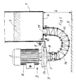
- a Filtration unit of this type also includes a reservoir 1 for the liquid to be filtered 2, from which this liquid by means of a Pump 3 must be removed so that it is under pressure on a filter (not shown) added to the more or less extensive filtration can be. Therefore, it goes without saying that a filtration unit such Art next to the reservoir and the pump a whole bunch of elements contains, such as the filter, the hydraulic components - pipes, valves, etc. - , the control organs, these components are not described here still shown, since they are not special in the context of the present invention Role-play.
- the pump 3 is therefore a conventional centrifugal pump and is outside of the reservoir 1 mounted vertically (i.e. the axis of rotation of the impeller t-t is aligned vertically) and the drive motor 6 above the Pump wheel of the pump 3 arranged.
- the pump wheel of pump 3 is in its annular shell 7 housed, and with m-m is the horizontal median plane of the pump wheel (not shown) indicated, whereby to achieve the necessary properties of a self-priming pump horizontal center plane m-m of the pump wheel by an amount u below the bottom 4 of the reservoir 1 is arranged, which is about half Value corresponds to the axial extension of the pump wheel (in the figure not shown, but based on the axial extent of the surrounding ring-shaped shell easily estimated).
- the annular casing 7 of the pump is connected to the reservoir 1 (or to any one other, not shown part of the filtration unit) by means of a rigid Carrier element 8 connected while between the bottom of the reservoir 1 and the intake manifold 9 of the pump 3, the connecting channel 10 coaxially with the impeller is arranged through which the liquid to be filtered from the reservoir 1 to the pump 3.
- This connecting channel 10 is corresponding to the known arrangement the prior art designed as a flexible tube 12 that the outlet nozzle 11 connects to the intake manifold 9 of the pump 3, wherein it forms an arc with a sufficiently large radius that gives the rigidity properties of the pipe.
- the flexible tube 12 is on the nozzle 9 and 11 connected in any suitable manner (e.g. by means of Briden or threaded connections), and is characterized in that a relatively large height h is required, which increases the overall size of the filter unit is unnecessarily enlarged in height, and by the fact that there is none has mechanical strength and therefore no supporting function can take over.
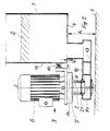
- the basic difference according to the invention is that the connecting channel 10 is rigid here and of a rigid Sheet metal cone 13 is formed, and that the connection between the connecting channel 10 and the intake manifold 9 of the pump 3 by means of a Damping and acting as a seal elastic element 14 accomplished is what is indicated in Fig. 2 in broad outline, and what in the following with the aid of a preferred embodiment shown in FIG. 3 to be explained in detail.
- the invention is mainly the interpretation that the connecting channel 10, formed by a sheet metal body 13, is rigid, and thus because he is also rigidly connected to the bottom 4 of the reservoir 1, also one Function as a load-bearing element on which the centrifugal pump 3 is attached. Thanks to this rigid training and the load capacity of the connecting channel 10 can the height distance h of the bottom 4 of the reservoir 1 must be kept to a minimum from the floor, making the first of the above Postulates for the present invention is fulfilled.
- FIG. 3 shows the manner in which on the inside of the pump 3 screwed socket 10, a sleeve 17 is screwed on the lower End by means of two webs 18 and 19, a pull rod 20 coaxial with the Stub 9 is attached.
- the rigidly configured connecting channel 10 Embodiment of the present invention a horizontal section of rectangular cross-section (with the channel cross-section in Fig. 2 dashed is indicated), on the upper horizontal surface 21 of the intake manifold 9 the pump 3 is attached.
- the particular advantage of this embodiment can be seen in that ideal conditions for attachment of the pump's neck, in that it is obvious is easier to close such a flange on a flat horizontal surface attach than on any other surface.
- the version shown represents however, by no means the only conceivable version of the connecting channel 10 represents
- the connecting channel 10 On the upper horizontal surface 21 of the connecting channel 10, which is preferably is designed as a channel with a rectangular cross section, is now a circular ring 22 corresponding to the placement of the intake manifold 9 welded, which has an annular groove in which a sealing ring 24 of circular cross-section, commonly referred to as an O-ring, receptacle finds.
- the pull rod 20 in turn protrudes below through an opening 25 out of the connecting channel 10, the pull rod 20 is sufficiently radial Leaves play, and is screwed into a round mounting plate 26, the one with a circular annular groove 27 for receiving another O-rings 28 is provided.
- the pull rod 20 is by means of the thread 29 in screwed the mounting plate 26 and pulled something against the sleeve 17, which is at most connected to the connection piece 9 via a seal 30, and is pulled against the O-ring 24 inserted in the circular ring 22, which ensures the attachment of the pump 3 on the connecting channel 10 becomes.
- the O-rings 24 and 28 up to the stop (i.e. until the surfaces are with the corresponding ring grooves and the respective counter surfaces touch directly) and that there is enough radial play between the axially drawn elements, so that an elastic connection without contact between metal surfaces is created in such a way that vibrations are not transmitted, and that perfect sealing is guaranteed.
- the special one allows Arrangement of the attachment of the pump 3 on the connecting channel 10, such as they are described using the exemplary embodiment shown in FIG. 3 was adhering to the pump 3 on the connecting channel 10 the least possible free space under the connecting channel 10 (In practical execution, twice the thickness of the Mounting plate 26) so that the height h can be kept to a minimum, as required by the specification of the present invention.
- a distance of this order of magnitude is particularly favorable for the Design for use in EDM machines.
- the present invention also provides that the inventive Filtration unit is preferably used as a filtration unit for the filtration of the dielectric liquid (be it water or any other another type of liquid) for an electrical discharge machining system.
- the inventive Filtration unit is preferably used as a filtration unit for the filtration of the dielectric liquid (be it water or any other another type of liquid) for an electrical discharge machining system.
- this represents a preferred application, as all the particular advantages that the present invention offers, can be fully exploited.
Landscapes
- Engineering & Computer Science (AREA)
- Mechanical Engineering (AREA)
- General Engineering & Computer Science (AREA)
- Structures Of Non-Positive Displacement Pumps (AREA)
Applications Claiming Priority (3)
| Application Number | Priority Date | Filing Date | Title |
|---|---|---|---|
| CH211697 | 1997-09-09 | ||
| CH211697 | 1997-09-09 | ||
| CH2116/97 | 1997-09-09 |
Publications (2)
| Publication Number | Publication Date |
|---|---|
| EP0902191A2 true EP0902191A2 (fr) | 1999-03-17 |
| EP0902191A3 EP0902191A3 (fr) | 1999-07-14 |
Family
ID=4226257
Family Applications (1)
| Application Number | Title | Priority Date | Filing Date |
|---|---|---|---|
| EP98810879A Withdrawn EP0902191A3 (fr) | 1997-09-09 | 1998-09-03 | Agencement d'une pompe centrifuge et son application |
Country Status (1)
| Country | Link |
|---|---|
| EP (1) | EP0902191A3 (fr) |
Cited By (2)
| Publication number | Priority date | Publication date | Assignee | Title |
|---|---|---|---|---|
| EP1571252A1 (fr) * | 2004-03-03 | 2005-09-07 | Electrolux Home Products Corporation N.V. | Pompe électrique pour machine à laver ou analogue |
| CN112283116A (zh) * | 2020-10-30 | 2021-01-29 | 天长市龙源泵阀有限公司 | 一种防泄漏耐腐蚀的化工泵 |
Family Cites Families (4)
| Publication number | Priority date | Publication date | Assignee | Title |
|---|---|---|---|---|
| BE336180A (fr) * | ||||
| FR436758A (fr) * | 1911-10-24 | 1912-04-04 | Ettore Bugatti | Dispositif pour raccorder à joint étanche les pompes des moteurs d'automobiles avec les réservoirs d'eau de refroidissement |
| US3026815A (en) * | 1958-02-26 | 1962-03-27 | Gen Motors Corp | Domestic appliance |
| DE29604168U1 (de) * | 1996-03-06 | 1996-06-05 | Schmalenberger GmbH & Co, 72072 Tübingen | Einrichtung zum Umwälzen von verunreinigten Flüssigkeiten |
-
1998
- 1998-09-03 EP EP98810879A patent/EP0902191A3/fr not_active Withdrawn
Cited By (2)
| Publication number | Priority date | Publication date | Assignee | Title |
|---|---|---|---|---|
| EP1571252A1 (fr) * | 2004-03-03 | 2005-09-07 | Electrolux Home Products Corporation N.V. | Pompe électrique pour machine à laver ou analogue |
| CN112283116A (zh) * | 2020-10-30 | 2021-01-29 | 天长市龙源泵阀有限公司 | 一种防泄漏耐腐蚀的化工泵 |
Also Published As
| Publication number | Publication date |
|---|---|
| EP0902191A3 (fr) | 1999-07-14 |
Similar Documents
| Publication | Publication Date | Title |
|---|---|---|
| DE2436080C3 (de) | Vorrichtung zum Abtrennen von öl von Wasser und Feststoffteilchen | |
| DE69609975T2 (de) | Wiederverwendbarer flüssigkeitsfilter und adapter. | |
| CH696552A5 (de) | Verbindung eines Rohrs mit einer Maschine. | |
| DE2162320A1 (fr) | ||
| DE10323068A1 (de) | Flüssigkeitstank | |
| DE60113122T2 (de) | Roboter zur vakuumreinigung von schwimmbädern unter druckzufuhr und vefahren | |
| DE112009004317T5 (de) | Fluidfilter mit Mutternplatte mit einer Dichtung an einer Endfläche und Aufbau zur äusseren Befestigung | |
| DE1293723B (de) | Absetzbehaelter fuer fluessige Medien, insbesondere fuer Wasser, Waschlaugen oder Schmieroel | |
| EP3222357B2 (fr) | Separateur de boue | |
| EP0276795A2 (fr) | Dispositif de filtration pour liquides pollués | |
| DE3043011C2 (de) | Vorrichtung zum kontinuierlichen Extrahieren von Flüssigkeit aus strömenden Suspensionen | |
| DE2621888B2 (de) | Stroemungsfilter | |
| EP1143066B1 (fr) | Dispositif de dégazage de suspension fibreuse | |
| EP1229986B1 (fr) | Element de filtre a tube ascendant | |
| DE2612905B2 (de) | Vorrichtung zum abzweigen von reinigungselementen | |
| EP0902191A2 (fr) | Agencement d'une pompe centrifuge et son application | |
| DE4333612C1 (de) | Absaugverfahren und Vorrichtungen hierfür | |
| DE69718801T2 (de) | Filter- und kühlvorrichtung | |
| EP1715200B1 (fr) | Articulation à rotule | |
| DE3818746C1 (en) | Pipe branch | |
| CH712415A2 (de) | Zentrifuge sowie Einsatz und Bodenelement für eine Zentrifuge. | |
| EP1166882A2 (fr) | Hydrocyclone | |
| EP1034829A1 (fr) | Unité de filtration comportant une multiplicité de filtres en forme de bougie | |
| DE2635923C3 (de) | Muffenventil | |
| DE2332456C2 (de) | Filter für einen Druckmittelbehälter |
Legal Events
| Date | Code | Title | Description |
|---|---|---|---|
| PUAI | Public reference made under article 153(3) epc to a published international application that has entered the european phase |
Free format text: ORIGINAL CODE: 0009012 |
|
| AK | Designated contracting states |
Kind code of ref document: A2 Designated state(s): CH DE FR IT LI |
|
| AX | Request for extension of the european patent |
Free format text: AL;LT;LV;MK;RO;SI |
|
| PUAL | Search report despatched |
Free format text: ORIGINAL CODE: 0009013 |
|
| RIC1 | Information provided on ipc code assigned before grant |
Free format text: 6F 04D 29/40 A, 6F 04D 29/66 B, 6F 04D 29/60 B, 6F 04D 29/08 B |
|
| AK | Designated contracting states |
Kind code of ref document: A3 Designated state(s): AT BE CH CY DE DK ES FI FR GB GR IE IT LI LU MC NL PT SE |
|
| AX | Request for extension of the european patent |
Free format text: AL;LT;LV;MK;RO;SI |
|
| 17P | Request for examination filed |
Effective date: 20000112 |
|
| AKX | Designation fees paid |
Free format text: CH DE FR IT LI |
|
| STAA | Information on the status of an ep patent application or granted ep patent |
Free format text: STATUS: THE APPLICATION IS DEEMED TO BE WITHDRAWN |
|
| 18D | Application deemed to be withdrawn |
Effective date: 20010403 |