EP0902191A2 - Arrangement of a centrifugal pump and its use - Google Patents
Arrangement of a centrifugal pump and its use Download PDFInfo
- Publication number
- EP0902191A2 EP0902191A2 EP98810879A EP98810879A EP0902191A2 EP 0902191 A2 EP0902191 A2 EP 0902191A2 EP 98810879 A EP98810879 A EP 98810879A EP 98810879 A EP98810879 A EP 98810879A EP 0902191 A2 EP0902191 A2 EP 0902191A2
- Authority
- EP
- European Patent Office
- Prior art keywords
- pump
- reservoir
- liquid
- arrangement
- arrangement according
- Prior art date
- Legal status (The legal status is an assumption and is not a legal conclusion. Google has not performed a legal analysis and makes no representation as to the accuracy of the status listed.)
- Withdrawn
Links
Images

Classifications
-
- F—MECHANICAL ENGINEERING; LIGHTING; HEATING; WEAPONS; BLASTING
- F04—POSITIVE - DISPLACEMENT MACHINES FOR LIQUIDS; PUMPS FOR LIQUIDS OR ELASTIC FLUIDS
- F04D—NON-POSITIVE-DISPLACEMENT PUMPS
- F04D29/00—Details, component parts, or accessories
- F04D29/40—Casings; Connections of working fluid
- F04D29/406—Casings; Connections of working fluid especially adapted for liquid pumps
-
- F—MECHANICAL ENGINEERING; LIGHTING; HEATING; WEAPONS; BLASTING
- F04—POSITIVE - DISPLACEMENT MACHINES FOR LIQUIDS; PUMPS FOR LIQUIDS OR ELASTIC FLUIDS
- F04D—NON-POSITIVE-DISPLACEMENT PUMPS
- F04D29/00—Details, component parts, or accessories
- F04D29/08—Sealings
- F04D29/086—Sealings especially adapted for liquid pumps
-
- F—MECHANICAL ENGINEERING; LIGHTING; HEATING; WEAPONS; BLASTING
- F04—POSITIVE - DISPLACEMENT MACHINES FOR LIQUIDS; PUMPS FOR LIQUIDS OR ELASTIC FLUIDS
- F04D—NON-POSITIVE-DISPLACEMENT PUMPS
- F04D29/00—Details, component parts, or accessories
- F04D29/60—Mounting; Assembling; Disassembling
- F04D29/605—Mounting; Assembling; Disassembling specially adapted for liquid pumps
-
- F—MECHANICAL ENGINEERING; LIGHTING; HEATING; WEAPONS; BLASTING
- F04—POSITIVE - DISPLACEMENT MACHINES FOR LIQUIDS; PUMPS FOR LIQUIDS OR ELASTIC FLUIDS
- F04D—NON-POSITIVE-DISPLACEMENT PUMPS
- F04D29/00—Details, component parts, or accessories
- F04D29/66—Combating cavitation, whirls, noise, vibration or the like; Balancing
- F04D29/669—Combating cavitation, whirls, noise, vibration or the like; Balancing especially adapted for liquid pumps
Definitions
- the present invention relates to an arrangement of a centrifugal pump for a filter unit for a liquid according to the preamble of the independent Claim 1 and the application of an inventive device of this type according to the preamble of claim 8.
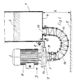
- this filtration is of very important because the liquid is not just cooling should effect, as with the other machines with abrasion removal, but also acts as a dielectric that acts directly as a medium in the electrical discharge machining process, through which the electrical discharges that propagate the EDM material. Since the workpiece is already being processed metal particles transported away the dielectric properties of the liquid change and reduce the erosion performance of the machine even more, the larger their number gets, it is imperative that the liquid is at the best possible Way can be filtered. That is why there are filtration units in practice that contain a horizontal bottom reservoir from from which the liquid reaches the suction port of a centrifugal pump, which is arranged coaxially to the impeller.
- the axis of rotation of the pump is arranged vertically outside the reservoir and by means of a connecting channel connected to this, which is designed as a flexible tube.
- a Carrier element attaches the pump directly to a vertical wall of the reservoir. So that the reservoir can be completely emptied, the middle level the impeller in practice by about half the axial extent of the pump wheel is arranged a little lower than the floor of the reservoir. This way the liquid can always be the impeller fill, even if the liquid has reached the lowest level in the reservoir, so the centrifugal pump, which is not self-priming when it is air or sucking bubbles, immersed in the liquid at all times and therefore how a self-priming pump works.
- the aim of the present invention is therefore to overcome the disadvantages mentioned above switch off known filtration units and propose a solution, which is both economically portable and applicable in filtration units, which form a unit with the machine tool, and which is also ideal Use of space allowed.
- the connecting channel is rigid, can this can be interpreted in such a way that, despite its large clear Cross-section requires as little overall height as possible and at the same time as a support element can serve for the pump, which is arranged vertically directly on the channel can be.
- the connection between the Channel and the intake manifold of the pump by means of an elastic element is accomplished, which in a first preferred embodiment is an O-ring is of circular cross section, the special advantages of vibration damping can be achieved, which are explained in more detail below become.
- Claim 8 then relates to a preferred application of the inventive Contraption.
- a Filtration unit of this type also includes a reservoir 1 for the liquid to be filtered 2, from which this liquid by means of a Pump 3 must be removed so that it is under pressure on a filter (not shown) added to the more or less extensive filtration can be. Therefore, it goes without saying that a filtration unit such Art next to the reservoir and the pump a whole bunch of elements contains, such as the filter, the hydraulic components - pipes, valves, etc. - , the control organs, these components are not described here still shown, since they are not special in the context of the present invention Role-play.
- the pump 3 is therefore a conventional centrifugal pump and is outside of the reservoir 1 mounted vertically (i.e. the axis of rotation of the impeller t-t is aligned vertically) and the drive motor 6 above the Pump wheel of the pump 3 arranged.
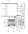
- the pump wheel of pump 3 is in its annular shell 7 housed, and with m-m is the horizontal median plane of the pump wheel (not shown) indicated, whereby to achieve the necessary properties of a self-priming pump horizontal center plane m-m of the pump wheel by an amount u below the bottom 4 of the reservoir 1 is arranged, which is about half Value corresponds to the axial extension of the pump wheel (in the figure not shown, but based on the axial extent of the surrounding ring-shaped shell easily estimated).
- the annular casing 7 of the pump is connected to the reservoir 1 (or to any one other, not shown part of the filtration unit) by means of a rigid Carrier element 8 connected while between the bottom of the reservoir 1 and the intake manifold 9 of the pump 3, the connecting channel 10 coaxially with the impeller is arranged through which the liquid to be filtered from the reservoir 1 to the pump 3.
- This connecting channel 10 is corresponding to the known arrangement the prior art designed as a flexible tube 12 that the outlet nozzle 11 connects to the intake manifold 9 of the pump 3, wherein it forms an arc with a sufficiently large radius that gives the rigidity properties of the pipe.
- the flexible tube 12 is on the nozzle 9 and 11 connected in any suitable manner (e.g. by means of Briden or threaded connections), and is characterized in that a relatively large height h is required, which increases the overall size of the filter unit is unnecessarily enlarged in height, and by the fact that there is none has mechanical strength and therefore no supporting function can take over.
- the basic difference according to the invention is that the connecting channel 10 is rigid here and of a rigid Sheet metal cone 13 is formed, and that the connection between the connecting channel 10 and the intake manifold 9 of the pump 3 by means of a Damping and acting as a seal elastic element 14 accomplished is what is indicated in Fig. 2 in broad outline, and what in the following with the aid of a preferred embodiment shown in FIG. 3 to be explained in detail.
- the invention is mainly the interpretation that the connecting channel 10, formed by a sheet metal body 13, is rigid, and thus because he is also rigidly connected to the bottom 4 of the reservoir 1, also one Function as a load-bearing element on which the centrifugal pump 3 is attached. Thanks to this rigid training and the load capacity of the connecting channel 10 can the height distance h of the bottom 4 of the reservoir 1 must be kept to a minimum from the floor, making the first of the above Postulates for the present invention is fulfilled.
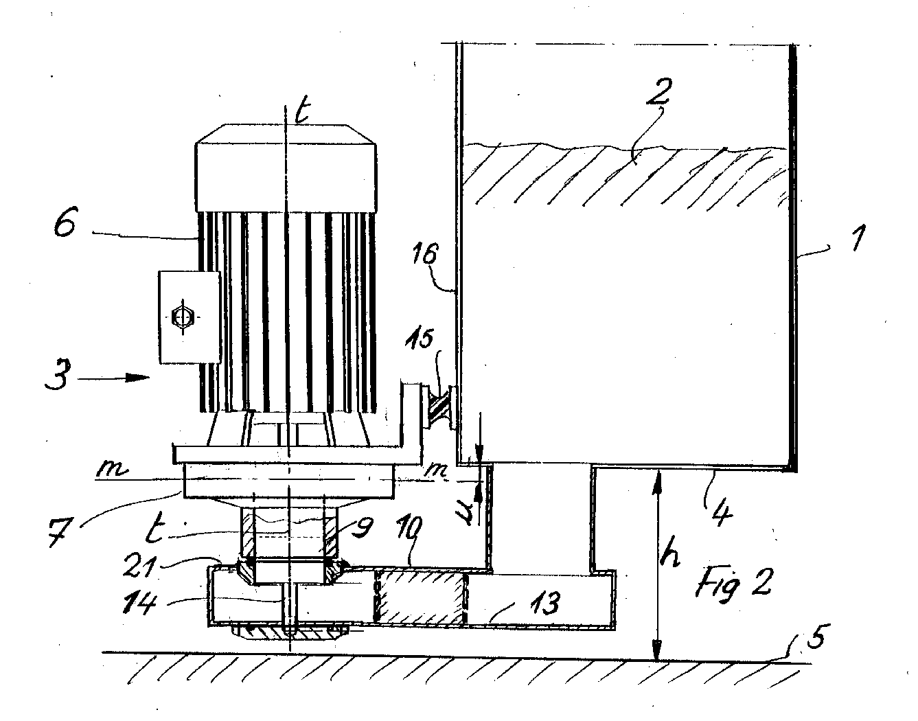
- FIG. 3 shows the manner in which on the inside of the pump 3 screwed socket 10, a sleeve 17 is screwed on the lower End by means of two webs 18 and 19, a pull rod 20 coaxial with the Stub 9 is attached.
- the rigidly configured connecting channel 10 Embodiment of the present invention a horizontal section of rectangular cross-section (with the channel cross-section in Fig. 2 dashed is indicated), on the upper horizontal surface 21 of the intake manifold 9 the pump 3 is attached.
- the particular advantage of this embodiment can be seen in that ideal conditions for attachment of the pump's neck, in that it is obvious is easier to close such a flange on a flat horizontal surface attach than on any other surface.
- the version shown represents however, by no means the only conceivable version of the connecting channel 10 represents
- the connecting channel 10 On the upper horizontal surface 21 of the connecting channel 10, which is preferably is designed as a channel with a rectangular cross section, is now a circular ring 22 corresponding to the placement of the intake manifold 9 welded, which has an annular groove in which a sealing ring 24 of circular cross-section, commonly referred to as an O-ring, receptacle finds.
- the pull rod 20 in turn protrudes below through an opening 25 out of the connecting channel 10, the pull rod 20 is sufficiently radial Leaves play, and is screwed into a round mounting plate 26, the one with a circular annular groove 27 for receiving another O-rings 28 is provided.
- the pull rod 20 is by means of the thread 29 in screwed the mounting plate 26 and pulled something against the sleeve 17, which is at most connected to the connection piece 9 via a seal 30, and is pulled against the O-ring 24 inserted in the circular ring 22, which ensures the attachment of the pump 3 on the connecting channel 10 becomes.
- the O-rings 24 and 28 up to the stop (i.e. until the surfaces are with the corresponding ring grooves and the respective counter surfaces touch directly) and that there is enough radial play between the axially drawn elements, so that an elastic connection without contact between metal surfaces is created in such a way that vibrations are not transmitted, and that perfect sealing is guaranteed.
- the special one allows Arrangement of the attachment of the pump 3 on the connecting channel 10, such as they are described using the exemplary embodiment shown in FIG. 3 was adhering to the pump 3 on the connecting channel 10 the least possible free space under the connecting channel 10 (In practical execution, twice the thickness of the Mounting plate 26) so that the height h can be kept to a minimum, as required by the specification of the present invention.
- a distance of this order of magnitude is particularly favorable for the Design for use in EDM machines.
- the present invention also provides that the inventive Filtration unit is preferably used as a filtration unit for the filtration of the dielectric liquid (be it water or any other another type of liquid) for an electrical discharge machining system.
- the inventive Filtration unit is preferably used as a filtration unit for the filtration of the dielectric liquid (be it water or any other another type of liquid) for an electrical discharge machining system.
- this represents a preferred application, as all the particular advantages that the present invention offers, can be fully exploited.
Landscapes
- Engineering & Computer Science (AREA)
- Mechanical Engineering (AREA)
- General Engineering & Computer Science (AREA)
- Structures Of Non-Positive Displacement Pumps (AREA)
Abstract
Die vorliegende Erfindung betrifft eine Anordnung einer Zentrifugalpumpe für ein Filtrieraggregat für eine Flüssigkeit, insbesondere für ein Filtrieraggregat für eine Flüssigkeit in einer Elektroerosionsmaschine.The present invention relates to an arrangement of a centrifugal pump for a filter unit for a liquid, in particular for a filter unit for a liquid in an EDM machine.
Bei solchen Vorrichtungen besteht die Forderung, den Abstand zwischen dem Reservoirboden (1) und dem Fussboden (5) möglichst klein zu halten, d.h. die Höhe (h) möglichst weitgehend zu reduzieren. Ferner soll vermieden werden, dass sich die Vibrationen der Pumpe (3) auf das Filtrieraggregat und allenfalls auf die ganze Werkzeugmaschine übertragen.In such devices, there is a requirement that the distance between the To keep the reservoir floor (1) and the floor (5) as small as possible, i.e. the Reduce height (h) as much as possible. Furthermore, it should be avoided that the vibrations of the pump (3) affect the filter unit and, if necessary transferred to the entire machine tool.
Zur Lösung dieser Probleme wird der Verbindungskanal (10), der das Flüssigkeitsreservoir
(1) mit dem Ansaugstutzen (9) der ausserhalb des Reservoirs
vertikal angeordneten Zentrifugalpumpe (3) verbindet, als starrer Kanal ausgebildet,
der mit dem Boden (4) des Reservoirs (1) starr verbunden ist, während
die Verbindung zwischen dem Kanal (10) und dem Ansaugstutzen (9) der
Pumpe (3) mittels einer dämpfenden elastischen Verbindung und mittels einer
Dichtung (14) bewerkstelligt wird, was der Pumpe (3) erlaubt, kleine Bewegungen
in allen Richtungen auszuführen, ohne dass diese auf das Filtrieraggregat
übertragen werden.
Description
Die vorliegende Erfindung betrifft eine Anordnung einer Zentrifugalpumpe für
ein Filtrieraggregat für eine Flüssigkeit gemäss dem Oberbegriff des unabhängigen
Anspruchs 1 und die Anwendung einer erfindungsgemässen Vorrichtung
dieser Art gemäss dem Oberbegriff des Anspruchs 8.The present invention relates to an arrangement of a centrifugal pump for
a filter unit for a liquid according to the preamble of the independent
Claim 1 and the application of an inventive device
of this type according to the preamble of
In der Praxis des Werkzeugmaschinenbaus steht man oft vor der Notwendigkeit, eine Bearbeitungsflüssigkeit zu filtrieren, um mehr oder weniger metallische harte Partikel daraus zu entfernen, die beim Materialabtragen anfallen. Dabei handelt es sich um Partikel mit sehr geringen Abmessungen, bis zu etwa 1 µm, besonders wenn die Werkzeugmaschine eine Schleifmaschine ist, oder insbesondere eine Maschine zum elektroerosiven Abtragen des Materials ist. In beiden Fällen müssen aus der Arbeitsflüssigkeit alle Partikel ausfiltriert werden, die in mindestens einer ihrer Abmessungen einen festgelegten Wert überschreiten (beispielsweise 1 µm), damit die Flüssigkeit wiederverwendet werden kann. Im speziellen Fall der Elektroerosion ist diese Filtrierung von ganz besonderer Wichtigkeit, da die Flüssigkeit, die nicht bloss eine Kühlung bewirken soll, wie bei den anderen Maschinen mit Abriebabfuhr, sondern auch als Dielektrikum wirkt, das direkt im Elektroerosionsprozess als Medium mitwirkt, durch welches sich die elektrischen Entladungen fortpflanzen, die das Material erodieren. Da die bereits vom in Bearbeitung stehenden Werkstück wegtransportierten Metallpartikel die dielektrischen Eigenschaften der Flüssigkeit verändern und die Erosionsleistung der Maschine um so stärker reduzieren, je grösser ihre Zahl wird, ist es unerlässlich, dass die Flüssigkeit auf bestmögliche Weise filtriert werden kann. Daher sind in der Praxis Filtrieraggregate entwickelt worden, die ein Reservoir mit horizontalem Boden enthalten, von dem aus die Flüssigkeit zum Ansaugstutzen einer Zentrifugalpumpe gelangt, der koaxial zum Pumpenrad angeordnet ist. Die Drehachse der Pumpe ist vertikal ausserhalb des Reservoirs angeordnet und mittels eines Verbindungskanals mit diesem verbunden, der als flexibles Rohr ausgebildet ist. Ein Trägerelement befestigt die Pumpe direkt an einer vertikalen Wand des Reservoirs. Damit das Reservoir vollständig geleert werden kann, wird die Mittelebene des Pumpenrads in Praxis um ein etwa der halben achsialen Ausdehnung des Pumpenrads entsprechendes Stück tiefer angeordnet als der Boden des Reservoirs. Auf diese Weise kann die Flüssigkeit das Pumpenrad immer füllen, auch wenn die Flüssigkeit den tiefsten Stand im Reservoir erreicht hat, so dass die Zentrifugalpumpe, die nicht selbstansaugend wirkt, wenn sie Luft oder Blasen ansaugt, jederzeit in die Flüssigkeit eintaucht und deshalb wie eine selbstansaugende Pumpe funktioniert.In the practice of machine tool construction, one is often faced with the need to filter a machining fluid to more or less metallic to remove hard particles from it that occur during material removal. These are particles with very small dimensions, up to about 1 µm, especially if the machine tool is a grinding machine, or in particular a machine for electroerosive removal of the material is. In both cases, all particles must be filtered out of the working fluid be a fixed value in at least one of their dimensions exceed (for example 1 µm) so that the liquid can be reused can be. In the special case of electroerosion, this filtration is of very important because the liquid is not just cooling should effect, as with the other machines with abrasion removal, but also acts as a dielectric that acts directly as a medium in the electrical discharge machining process, through which the electrical discharges that propagate the EDM material. Since the workpiece is already being processed metal particles transported away the dielectric properties of the liquid change and reduce the erosion performance of the machine even more, the larger their number gets, it is imperative that the liquid is at the best possible Way can be filtered. That is why there are filtration units in practice that contain a horizontal bottom reservoir from from which the liquid reaches the suction port of a centrifugal pump, which is arranged coaxially to the impeller. The axis of rotation of the pump is arranged vertically outside the reservoir and by means of a connecting channel connected to this, which is designed as a flexible tube. A Carrier element attaches the pump directly to a vertical wall of the reservoir. So that the reservoir can be completely emptied, the middle level the impeller in practice by about half the axial extent of the pump wheel is arranged a little lower than the floor of the reservoir. This way the liquid can always be the impeller fill, even if the liquid has reached the lowest level in the reservoir, so the centrifugal pump, which is not self-priming when it is air or sucking bubbles, immersed in the liquid at all times and therefore how a self-priming pump works.
Diese Lösung bietet den Vorteil einer einfachen und kostengünstigen Ausgestaltung,
weil eine Zentrifugalpumpe wirtschaftlichster Bauart verwendet werden
kann, die nicht mit den selbstansaugenden Tauchpumpen vergleichbar ist,
die normalerweise zur Lösung solcher Aufgaben eingesetzt werden. Dennoch
weist diese Lösung noch zwei wesentliche Nachteile auf, nämlich:
Ziel der vorliegenden Erfindung ist daher, die oben genannten Nachteile der bekannten Filtrieraggregate auszuschalten und eine Lösung vorzuschlagen, die sowohl wirtschaftlich tragbar als auch in Filtrieraggregaten anwendbar ist, die mit der Werkzeugmaschine eine Einheit bilden, und die darüber hinaus ideale Platzausnützung erlaubt.The aim of the present invention is therefore to overcome the disadvantages mentioned above switch off known filtration units and propose a solution, which is both economically portable and applicable in filtration units, which form a unit with the machine tool, and which is also ideal Use of space allowed.
Diese Zielsetzungen werden erfüllt mit einer Anordnung einer Zentrifugalpumpe für ein Filtrieraggregat für eine Flüssigkeit der im Oberbegriff des unabhängigen Patentanspruchs 1 genannten Art, welche im charakterisierenden Teil des Patentanspruchs 1 der vorliegenden Erfindung gekennzeichnet ist.These objectives are met with an arrangement of a centrifugal pump for a filter unit for a liquid which in the preamble of the independent Claim mentioned type, which in the characterizing part of claim 1 of the present invention.
Dank der Anordnung, dass der Verbindungskanal starr ausgebildet ist, kann dieser in solcher Weise ausgelegt werden, dass er trotz seines grossen lichten Querschnittes möglichst wenig Bauhöhe beansprucht und zugleich als Trägerelement für die Pumpe dienen kann, die vertikal direkt auf dem Kanal angeordnet werden kann. Dank der Anordnung, dass die Verbindung zwischen dem Kanal und dem Ansaugstutzen der Pumpe mittels eines elastischen Elementes bewerkstelligt wird, das in einer ersten bevorzugten Ausführungsform ein O-Ring von kreisrundem Querschnitt ist, können die besonderen Vorteile der Vibrationsdämpfung erreicht werden, die im Folgenden detailliert weiter erklärt werden. Thanks to the arrangement that the connecting channel is rigid, can this can be interpreted in such a way that, despite its large clear Cross-section requires as little overall height as possible and at the same time as a support element can serve for the pump, which is arranged vertically directly on the channel can be. Thanks to the arrangement that the connection between the Channel and the intake manifold of the pump by means of an elastic element is accomplished, which in a first preferred embodiment is an O-ring is of circular cross section, the special advantages of vibration damping can be achieved, which are explained in more detail below become.
Die abhängigen Ansprüche 3 bis 7 betreffen weitere Verbesserungen der Erfindungsidee,
deren Vorteile im Folgenden unter Bezugnahme auf verschiedene
in den Figuren dargestellten Ausführungsbeispiele näher erklärt werden.The
Der Patentanspruch 8 sodann betrifft eine bevorzugte Anwendung der erfindungsgemässen
Vorrichtung.
Die vorliegende Erfindung ist im Folgenden anhand der in den entsprechenden Figuren dargestellten Ausführungsbeispielen näher erklärt. Es zeigen die:
- Fig. 1
- Eine Anordnung einer Zentrifugalpumpe für ein Filtrieraggregat gemäss dem bekannten Stand der Technik,
- Fig. 2
- Eine Anordnung einer Zentrifugalpumpe für ein Filtrieraggregat gemäss der vorliegenden Erfindung,
- Fig. 3
- Ein Detail der Verbindungszone zwischen der Pumpe gemäss der Fig. 2 und dem Verbindungskanal.
- Fig. 1
- An arrangement of a centrifugal pump for a filter unit according to the known prior art,
- Fig. 2
- An arrangement of a centrifugal pump for a filter unit according to the present invention,
- Fig. 3
- A detail of the connection zone between the pump according to FIG. 2 and the connection channel.
In der Fig. 1 ist eine Anordnung einer Zentrifugalpumpe für ein Filtrieraggregat
dargestellt, wie es beispielsweise bei verschiedenen Arten von Werkzeugmaschinen
Verwendung findet, insbesondere bei Elektroerosionsmaschinen. Ein
Filtrieraggregat dieser Art umfasst unter anderem auch ein Reservoir 1 für die
zu filtrierende Flüssigkeit 2, aus welchem diese Flüssigkeit mittels einer
Pumpe 3 entnommen werden muss, damit sie unter Druck auf einen Filter
(nicht gezeigt) zur mehr oder weniger weit getriebenen Filtrierung gegeben
werden kann. Daher versteht sich von selbst, dass ein Filtrieraggregat solcher
Art neben dem Reservoir und der Pumpe eine ganze Reihe von Elementen
enthält, wie z.B. den Filter, die Hydraulikkomponenten - Rohre, Ventile, usw. -
, die Steuerungsorgane, diese Komponenten sind hier weder beschrieben
noch dargestellt, da sie im Rahmen der vorliegenden Erfindung keine besondere
Rolle spielen.1 shows an arrangement of a centrifugal pump for a filtration unit
shown, as is the case for example with different types of machine tools
Is used, especially in electrical discharge machines. A
Filtration unit of this type also includes a reservoir 1 for the
liquid to be filtered 2, from which this liquid by means of a
Für die vorliegende Erfindung sind die folgenden Punkte von grundlegender
Bedeutung:
Die in der Fig. 1 dargestellte herkömmliche Anordnung trägt den genannten Anforderungen für optimale Verhältnisse nur teilweise Rechnung, wie nun erklärt werden soll.The conventional arrangement shown in Fig. 1 carries the above Requirements for optimal conditions only partially account, as now explained shall be.
Die Pumpe 3 ist also eine gewöhnliche Zentrifugalpumpe und ist ausserhalb
des Reservoirs 1 vertikal angeordnet montiert (d.h. die Drehachse des Pumpenrades
t-t ist vertikal ausgerichtet) und der Antriebsmotor 6 oberhalb des
Pumpenrades der Pumpe 3 angeordnet. Das Pumpenrad der Pumpe 3 ist in
seiner ringförmigen Hülle 7 untergebracht, und mit m-m ist die horizontale Mittelebene
des Pumpenrades (nicht dargestellt) angedeutet, wobei zum Erreichen
der notwendigen Eigenschaften einer selbstansaugenden Pumpe die
horizontale Mittelebene m-m des Pumpenrades um einen Höhenbetrag u unterhalb
des Bodens 4 des Reservoirs 1 angeordnet ist, der etwa dem halben
Wert der achsialen Ausdehnung des Pumpenrades entspricht (in der Figur
nicht dargestellt, aber anhand der achsialen Ausdehnung der es umgebenden
ringförmigen Hülle leicht abzuschätzen).The
Dank dieser Anordnung des Pumpenrads der Pumpe 3 bleibt dieses immer in
die Flüssigkeit eingetaucht, selbst wenn das Flüssigkeitsniveau im Reservoir 1
den tiefsten zulässigen Stand erreicht hat, so dass die Zentrifugalpumpe wie
eine selbstansaugende Pumpe funktioniert.Thanks to this arrangement of the pump wheel of the
Die ringförmige Hülle 7 der Pumpe ist mit dem Reservoir 1 (oder mit irgendeinem
anderen, nicht gezeigten Teil des Filtrieraggregats) mittels eines starren
Trägerelementes 8 verbunden, während zwischen dem Boden des Reservoirs
1 und dem Ansaugstutzen 9 der Pumpe 3 der Verbindungskanal 10 koaxial mit
dem Pumpenrad angeordnet ist, durch welchen die zu filtrierende Flüssigkeit
vom Reservoir 1 zur Pumpe 3 gelangt.The
Dieser Verbindungskanal 10 ist gemäss der bekannten Anordnung entsprechend
dem Stand der Technik als flexibles Rohr 12 ausgebildet, das den Ausgangsstutzen
11 mit dem Ansaugstutzen 9 der Pumpe 3 verbindet, wobei es
einen Bogen mit genügend grossem Radius bildet, der den Steifigkeitseigenschaften
des Rohrs Rechnung trägt. Das flexible Rohr 12 wird an den Stutzen
9 und 11 in irgendeiner geeigneten Weise angeschlossen (beispielsweise mittels
Briden oder Gewindeanschlüssen), und ist dadurch gekennzeichnet, dass
eine relativ grosse Höhe h erforderlich ist, wodurch die Gesamtgrösse des Filtrieraggregats
in der Höhe unnötig vergrössert wird, und dadurch, dass es keinerlei
mechanische Festigkeit aufweist und daher keinerlei tragende Funktion
übernehmen kann. Dies sind die Einschränkungen, die sich aus der herkömmlichen
Konstruktion ergeben, und gegen welche die vorliegende Erfindung Abhilfe
schaffen will, wie dies nun anhand der Fig. 2 erklärt werden soll, in der die
erfindungsgemässe Anordnung gezeigt ist, die jener gemäss der Fig. 1 gleicht,
ohne jedoch deren erwähnte Nachteile aufzuweisen.This connecting
In der Fig. 2 sind die gleichen Elemente, wie sie in der Anordnung gemäss der Fig. 1 gezeigt sind, mit den gleichen Bezugsziffern bezeichnet.2 are the same elements as in the arrangement according to the Fig. 1 are shown, designated by the same reference numerals.
Der grundlegende und erfindungsgemässe Unterschied besteht darin, dass
der Verbindungskanal 10 hier starr ausgebildet ist und von einem starren
Blechkonus 13 gebildet wird, und dass die Verbindung zwischen dem Verbindungskanal
10 und dem Ansaugstutzen 9 der Pumpe 3 mittels eines als
Dämpfung und als Dichtung wirkenden elastischen Elementes 14 bewerkstelligt
wird, was in der Fig. 2 lediglich in grossen Zügen angedeutet ist, und was
im Folgenden anhand einer in der Fig. 3 dargestellten bevorzugten Ausführungsform
in allen Einzelheiten erklärt werden soll. Wichtig für die Wirksamkeit
der Erfindung ist hauptsächlich die Auslegung, dass der Verbindungskanal 10,
von einem Blechkörper 13 gebildet, starr ausgebildet ist, und der somit, da er
mit dem Boden 4 des Reservoirs 1 ebenfalls starr verbunden ist, auch eine
Funktion als tragendes Element übernehmen kann, auf dem die Zentrifugalpumpe
3 befestigt wird. Dank dieser starren Ausbildung und der Tragfähigkeit
des Verbindungskanals 10 kann der Höhenabstand h des Bodens 4 des Reservoirs
1 vom Fussboden minimal gehalten werden, womit das erste der genannten
Postulate für die vorliegende Erfindung erfüllt ist.The basic difference according to the invention is that
the connecting
Sodann erlaubt die Anordnung eines Verbindungselementes zwischen dem
Ansaugstutzen 9 der Pumpe 3 und dem Verbindungskanal 10, das als elastisches
Dämpfungselement und als Dichtung 14 ausgebildet ist, eine Übertragung
der unvermeidlichen Vibrationen der Pumpe 3 - welche Vibrationen erfahrungsgemäss
vor allem in achsialer Richtung der Pumpe 3 wirken - auf das
Reservoir 1 oder auf das ganze Filtrieraggregat zu verhindern, womit das
zweite grundlegende Postulat für die vorliegende Erfindung erfüllt ist. Aus Stabilitätsgründen
kann die Pumpe 3 gemäss einer bevorzugten Ausführungsform
der vorliegenden Erfindung auch noch zusätzlich an der senkrechten Wand 16
des Reservoirs 1 mittels eines Supports 15 befestigt werden, der entsprechende
Dämpfungselemente enthält.Then allows the arrangement of a connecting element between the
Eine bevorzugte Ausführungsform des elastischen Verbindungselementes 14
zwischen dem starren Verbindungskanal 10 und dem Ansaugstutzen 9 der
Pumpe 3 wird im Folgenden unter Bezugnahme auf die Fig. 3 näher beschrieben.
Es sei jedoch sogleich festgehalten, dass es sich dabei lediglich um eine
von vielen denkbaren Lösungen handelt, die sich eignen, das Problem der Befestigung
der Pumpe 3 auf dem Verbindungskanal 10 zu lösen, und nicht etwa
um die einzige im Rahmen der vorliegenden Erfindung mögliche Lösung. Die
in der Fig. 3 dargestellte Lösung weist, vom praktischen Standpunkt betrachtet,
Vorteile auf bezüglich Montage und Anpassbarkeit an einen marktgängigen
Pumpentyp, der einen mit Gewinde versehenen Stutzen aufweist, und unter
diesem Aspekt kann von einer bevorzugten Lösung gesprochen werden.A preferred embodiment of the elastic connecting
In der Fig. 3 ist dargestellt, auf welche Weise auf dem im Innern der Pumpe 3
eingeschraubten Stutzen 10 eine Büchse 17 aufgeschraubt ist, an deren unterem
Ende mittels zweier Stege 18 und 19 eine Zugstange 20 koaxial mit dem
Stutzen 9 befestigt ist.3 shows the manner in which on the inside of the
Der starr ausgebildete Verbindungskanal 10 weist gemäss einer bevorzugten
Ausführungsform der vorliegenden Erfindung eine horizontale Partie von
rechteckigem Querschnitt auf (wobei der Kanalquerschnitt in der Fig. 2 gestrichelt
angedeutet ist), auf deren oberen horizontalen Oberfläche 21 der Ansaugstutzen
9 der Pumpe 3 befestigt wird. Der besondere Vorteil dieser Ausführungsform
ist darin zu sehen, dass ideale Voraussetzungen für die Befestigung
des Stutzens der Pumpe geschaffen werden, insofern als es offensichtlich
leichter ist, einen solchen Flansch auf einer ebenen horizontalen Fläche zu
befestigen als auf irgendeiner anderen Fläche. Die gezeigte Ausführung stellt
jedoch keineswegs die einzige denkbare Ausführung des Verbindungskanals
10 dar.According to a preferred embodiment, the rigidly configured connecting
Auf der oberen horizontalen Fläche 21 des Verbindungskanals 10, der vorzugsweise
als Kanal mit rechteckigem Querschnitt ausgebildet ist, wird nun
entsprechend der Plazierung des Ansaugstutzens 9 ein kreisrunder Ring 22
aufgeschweisst, der eine ringförmige Nut aufweist, in welcher ein Dichtungsring
24 von kreisrundem Querschnitt, gewöhnlich als O-Ring bezeichnet, Aufnahme
findet. Die Zugstange 20 ihrerseits ragt unten durch eine Öffnung 25
aus dem Verbindungskanal 10 heraus, die der Zugstange 20 genügend radiales
Spiel freilässt, und wird in einen runden Befestigungsteller 26 eingeschraubt,
der mit einer kreisrunden Ringnut 27 zur Aufnahme eines weiteren
O-Rings 28 versehen ist. Die Zugstange 20 wird mittels des Gewindes 29 in
den Befestigungsteller 26 eingeschraubt und etwas gegen die Büchse 17 gezogen,
die allenfalls über eine Dichtung 30 mit dem Stutzen 9 verbunden ist,
und wird gegen den im kreisrunden Ring 22 eingelegten O-Ring 24 gezogen,
wodurch die Befestigung der Pumpe 3 auf dem Verbindungskanal 10 sichergestellt
wird. Bei der Montage ist darauf zu achten, dass keine der Dichtungen
aus Gummi, die O-Ringe 24 und 28, bis zum Anschlag (d.h. bis sich die Oberflächen
mit den entsprechenden Ringnuten und die jeweiligen Gegenflächen
direkt berühren) angezogen wird, und ebenso, dass genügend radiales Spiel
zwischen den achsial gegeneinander gezogenen Elemente erhalten bleibt, so
dass eine elastische Verbindung ohne Berührung zwischen Metall-Oberflächen
solchermassen erstellt wird, dass Vibrationen nicht übertragen werden,
und dass perfekte Abdichtung gewährleistet ist. Ferner erlaubt die besondere
Anordnung der Befestigung der Pumpe 3 auf dem Verbindungskanal10, wie
sie anhand des in der Fig. 3 dargestellten Ausführungsbeispiels beschrieben
wurde, das Befestigen der Pumpe 3 auf dem Verbindungskanal 10 unter Einhaltung
eines geringstmöglichen freien Raums unter dem Verbindungskanal
10 (In der praktischen Ausführung genügt der doppelte Wert der Dicke des
Befestigungstellers 26), so dass die Höhe h minimal gehalten werden kann,
wie es das Pflichtenheft der vorliegenden Erfindung fordert.On the upper
Gemäss einer weiteren bevorzugten Ausführungsform der vorliegenden Erfindung
beträgt der Abstand u, zwischen der horizontalen Mittelebene m-m des
Pumpenrades und der inneren Oberfläche des Bodens 4 des Reservoirs 1, 5
bis 15 mm. Ein Abstand dieser Grössenordnung ist besonders günstig für die
Auslegung zur Anwendung in Elektroerosionsmaschinen.According to a further preferred embodiment of the present invention
is the distance u between the horizontal center plane m-m of
Pump wheel and the inner surface of the
Die vorliegende Erfindung sieht schliesslich auch vor, dass das erfindungsgemässe Filtrieraggregat als ein Filtrieraggregat vorzugsweise Anwendung findet für die Filtrierung der Dielektrikumsflüssigkeit (sei es Wasser oder irgendeine andere Art von Flüssigkeit) für eine Elektroerosionsanlage. Dies stellt insofern eine bevorzugte Anwendung dar, als alle die besonderen Vorteile, welche die vorliegende Erfindung bietet, voll ausgenützt werden können. Finally, the present invention also provides that the inventive Filtration unit is preferably used as a filtration unit for the filtration of the dielectric liquid (be it water or any other another type of liquid) for an electrical discharge machining system. In this respect, this represents a preferred application, as all the particular advantages that the present invention offers, can be fully exploited.
- 1.1.
- Reservoirreservoir
- 2.2nd
- zu filtrierende Flüssigkeitliquid to be filtered
- 3.3rd
- Pumpepump
- 4.4th
- ReservoirbodenReservoir floor
- 5.5.
- FussbodenFloor
- 6.6.
- AntriebsmotorDrive motor
- 7.7.
- ringförmige Hülleannular shell
- 8.8th.
- TrägerelementCarrier element
- 9.9.
- AnsaugstutzenIntake manifold
- 10.10th
- VerbindungskanalConnecting channel
- 11.11.
- AuslaufstutzenOutlet connection
- 12.12th
- flexibles Rohrflexible pipe
- 13.13.
- Behälter aus BlechTin containers
- 14.14.
- elastische Verbindungelastic connection
- 15.15.
- TrägerelementCarrier element
- 16.16.
- vertikale Wandvertical wall
- 17.17th
- GewindebüchseThreaded sleeve
- 18.18th
- Stegweb
- 19.19th
- Stegweb
- 20.20th
- Zugstangepull bar
- 21.21.
- horizontale obere Oberfläche des Verbindungskanalshorizontal upper surface of the connecting channel
- 22.22.
- Ring mit kreisrundem QuerschnittRing with a circular cross-section
- 23.23.
- RingnutRing groove
- 24.24th
- O-RingO-ring
- 25.25th
- Durchgangsöffnung Through opening
- 26.26.
- BefestigungstellerMounting plate
- 27.27.
- RingnutRing groove
- 28.28
- O-RingO-ring
- 29.29.
- Gewindethread
- 30.30th
- Dichtungpoetry
Claims (8)
wobei die horizontale Mittelebene (m-m) des Pumpenrades um einen Höhenbetrag (u) unterhalb des Bodens (4) des Reservoirs (1) liegt, der ungefähr der Hälfte der achsialen Abmessung des Pumpenrades entspricht,
dadurch gekennzeichnet, dass
der Verbindungskanal (10) starr ausgebildet ist und starr mit dem Boden (4) des Reservoirs (1) verbunden ist, und dass die Verbindung zwischen dem Kanal (10) und dem Ansaugstutzen (9) der Pumpe (3) mittels einer elastischen Verbindung als Dämpfungselement und als Dichtungselement (14) bewerkstelligt wird.Arrangement of a centrifugal pump for a filter unit for a liquid, with
wherein the horizontal central plane (mm) of the pump wheel lies below the bottom (4) of the reservoir (1) by an amount of height (u) which corresponds approximately to half the axial dimension of the pump wheel,
characterized in that
the connecting channel (10) is rigid and is rigidly connected to the bottom (4) of the reservoir (1), and that the connection between the channel (10) and the intake (9) of the pump (3) by means of an elastic connection as Damping element and as a sealing element (14) is accomplished.
dadurch gekennzeichnet, dass
die Verbindung (14) mindestens einen O-Ring von kreisrundem Querschnitt umfasst.Arrangement according to claim 1,
characterized in that
the connection (14) comprises at least one O-ring of circular cross-section.
dadurch gekennzeichnet, dass
der Verbindungskanal (10) eine horizontale Partie von rechteckigem Querschnitt aufweist, auf deren oberen horizontalen Oberfläche (21) der Ansaugstutzen (9) der Pumpe (3) befestigt wird. Arrangement according to claim 1,
characterized in that
the connecting channel (10) has a horizontal section of rectangular cross-section, on the upper horizontal surface (21) of which the suction nozzle (9) of the pump (3) is fastened.
dadurch gekennzeichnet, dass
die Befestigung der Pumpe (3) mittels einer Zugstange (20) bewerkstelligt wird, die an einer im Ansaugstutzen (9) eingeschraubten Büchse (17) befestigt ist, die den Ansaugstutzen (9) gegen die Befestigungs-Oberfläche eines kreisrunden Rings (22) zieht, wobei zwischen der Befestigungs-Oberfläche des Rings (22) und der runden Büchse (17) ein O-Ring (24) von kreisrundem Querschnitt eingelegt ist.Arrangement according to claims 2 and 3,
characterized in that
the pump (3) is fastened by means of a pull rod (20) which is fastened to a bushing (17) screwed into the intake port (9), which pulls the intake port (9) against the mounting surface of a circular ring (22) , an O-ring (24) of circular cross-section being inserted between the fastening surface of the ring (22) and the round sleeve (17).
dadurch gekennzeichnet, dass
die Zugstange (20) an einer mit einem Gewinde versehenen Büchse (17) befestigt ist, die in das Innengewinde im Ansaugstutzen (9) eingeschraubt wird.Arrangement according to claim 4,
characterized in that
the pull rod (20) is fastened to a threaded bushing (17) which is screwed into the internal thread in the intake socket (9).
dadurch gekennzeichnet, dass
der Abstand (u) zwischen der horizontalen Mittelebene (m-m) des Pumpenrades und der Innenfläche des Bodens (4) des Reservoirs (1) zwischen 5 und 15 mm beträgt.Arrangement according to claim 1,
characterized in that
the distance (u) between the horizontal central plane (mm) of the pump wheel and the inner surface of the bottom (4) of the reservoir (1) is between 5 and 15 mm.
dadurch gekennzeichnet, dass
die Zentrifugalpumpe zusätzlich mittels eines Trägerelementes (15), das entsprechende Dämpfungselemente enthält, an einer vertikalen Wand (16) des Reservoirs (1) befestigt ist.Arrangement according to claim 1,
characterized in that
the centrifugal pump is additionally fastened to a vertical wall (16) of the reservoir (1) by means of a carrier element (15) which contains corresponding damping elements.
das Filtrieraggregat als Filtrieraggregat der Dielektrikumsflüssigkeit in einer Elektroerosionsanlage ausgelegt ist.Application of the arrangement of the centrifugal pump according to claim 1, characterized in that
the filtering unit is designed as a filtering unit for the dielectric liquid in an electrical discharge machining system.
Applications Claiming Priority (3)
| Application Number | Priority Date | Filing Date | Title |
|---|---|---|---|
| CH211697 | 1997-09-09 | ||
| CH211697 | 1997-09-09 | ||
| CH2116/97 | 1997-09-09 |
Publications (2)
| Publication Number | Publication Date |
|---|---|
| EP0902191A2 true EP0902191A2 (en) | 1999-03-17 |
| EP0902191A3 EP0902191A3 (en) | 1999-07-14 |
Family
ID=4226257
Family Applications (1)
| Application Number | Title | Priority Date | Filing Date |
|---|---|---|---|
| EP98810879A Withdrawn EP0902191A3 (en) | 1997-09-09 | 1998-09-03 | Arrangement of a centrifugal pump and its use |
Country Status (1)
| Country | Link |
|---|---|
| EP (1) | EP0902191A3 (en) |
Cited By (2)
| Publication number | Priority date | Publication date | Assignee | Title |
|---|---|---|---|---|
| EP1571252A1 (en) * | 2004-03-03 | 2005-09-07 | Electrolux Home Products Corporation N.V. | Electric motor-driven pump for washing machines and the like |
| CN112283116A (en) * | 2020-10-30 | 2021-01-29 | 天长市龙源泵阀有限公司 | Prevent leaking corrosion resistant chemical pump |
Family Cites Families (4)
| Publication number | Priority date | Publication date | Assignee | Title |
|---|---|---|---|---|
| BE336180A (en) * | ||||
| FR436758A (en) * | 1911-10-24 | 1912-04-04 | Ettore Bugatti | Device for sealingly connecting automobile engine pumps to cooling water tanks |
| US3026815A (en) * | 1958-02-26 | 1962-03-27 | Gen Motors Corp | Domestic appliance |
| DE29604168U1 (en) * | 1996-03-06 | 1996-06-05 | Schmalenberger GmbH & Co, 72072 Tübingen | Device for circulating contaminated liquids |
-
1998
- 1998-09-03 EP EP98810879A patent/EP0902191A3/en not_active Withdrawn
Cited By (2)
| Publication number | Priority date | Publication date | Assignee | Title |
|---|---|---|---|---|
| EP1571252A1 (en) * | 2004-03-03 | 2005-09-07 | Electrolux Home Products Corporation N.V. | Electric motor-driven pump for washing machines and the like |
| CN112283116A (en) * | 2020-10-30 | 2021-01-29 | 天长市龙源泵阀有限公司 | Prevent leaking corrosion resistant chemical pump |
Also Published As
| Publication number | Publication date |
|---|---|
| EP0902191A3 (en) | 1999-07-14 |
Similar Documents
| Publication | Publication Date | Title |
|---|---|---|
| DE2436080C3 (en) | Device for separating oil from water and solid particles | |
| DE69609975T2 (en) | REUSABLE LIQUID FILTER AND ADAPTER. | |
| CH696552A5 (en) | Connecting a tube to a machine. | |
| DE2162320A1 (en) | ||
| DE10323068A1 (en) | Fluid tank has bubble removal device inside it, with cyclone chamber to create vortex in fluid, and flow outlet through which can flow bubble free fluid from cyclone chamber, and outlet for escape of bubbles separated from fluid | |
| DE60113122T2 (en) | ROBOT FOR VACUUM CLEANING OF SWIMMING POOLS UNDER PRESSURE AND EXPERIENCE | |
| DE112009004317T5 (en) | Fluid filter with nut plate with a seal on one end surface and structure for external attachment | |
| DE1293723B (en) | Settling tank for liquid media, especially for water, washing solutions or lubricating oil | |
| EP3222357B2 (en) | Sludge separator | |
| EP0276795A2 (en) | Filtering device for polluted liquids | |
| DE3043011C2 (en) | Device for the continuous extraction of liquid from flowing suspensions | |
| DE2621888B2 (en) | FLOW FILTER | |
| EP1143066B1 (en) | Device for degassing fibrous suspension | |
| EP1229986B1 (en) | Filter element provided with an ascending pipe | |
| DE2612905B2 (en) | DEVICE FOR DIVIDING CLEANING ELEMENTS | |
| EP0902191A2 (en) | Arrangement of a centrifugal pump and its use | |
| DE4333612C1 (en) | Suction method and devices for this | |
| DE69718801T2 (en) | FILTER AND COOLING DEVICE | |
| EP1715200B1 (en) | Ball joint connection | |
| DE3818746C1 (en) | Pipe branch | |
| CH712415A2 (en) | Centrifuge and insert and bottom element for a centrifuge. | |
| EP1166882A2 (en) | Hydrocyclone | |
| EP1034829A1 (en) | Filtering unit with a plurality of filter cartridges | |
| DE2635923C3 (en) | In-line valve | |
| DE2332456C2 (en) | Filter for a pressure medium tank |
Legal Events
| Date | Code | Title | Description |
|---|---|---|---|
| PUAI | Public reference made under article 153(3) epc to a published international application that has entered the european phase |
Free format text: ORIGINAL CODE: 0009012 |
|
| AK | Designated contracting states |
Kind code of ref document: A2 Designated state(s): CH DE FR IT LI |
|
| AX | Request for extension of the european patent |
Free format text: AL;LT;LV;MK;RO;SI |
|
| PUAL | Search report despatched |
Free format text: ORIGINAL CODE: 0009013 |
|
| RIC1 | Information provided on ipc code assigned before grant |
Free format text: 6F 04D 29/40 A, 6F 04D 29/66 B, 6F 04D 29/60 B, 6F 04D 29/08 B |
|
| AK | Designated contracting states |
Kind code of ref document: A3 Designated state(s): AT BE CH CY DE DK ES FI FR GB GR IE IT LI LU MC NL PT SE |
|
| AX | Request for extension of the european patent |
Free format text: AL;LT;LV;MK;RO;SI |
|
| 17P | Request for examination filed |
Effective date: 20000112 |
|
| AKX | Designation fees paid |
Free format text: CH DE FR IT LI |
|
| STAA | Information on the status of an ep patent application or granted ep patent |
Free format text: STATUS: THE APPLICATION IS DEEMED TO BE WITHDRAWN |
|
| 18D | Application deemed to be withdrawn |
Effective date: 20010403 |