EP0899693A2 - Bildanzeigevorrichtung und Verfahren - Google Patents
Bildanzeigevorrichtung und Verfahren Download PDFInfo
- Publication number
- EP0899693A2 EP0899693A2 EP98306843A EP98306843A EP0899693A2 EP 0899693 A2 EP0899693 A2 EP 0899693A2 EP 98306843 A EP98306843 A EP 98306843A EP 98306843 A EP98306843 A EP 98306843A EP 0899693 A2 EP0899693 A2 EP 0899693A2
- Authority
- EP
- European Patent Office
- Prior art keywords
- image
- tomographic
- viewpoint
- display apparatus
- synchro
- Prior art date
- Legal status (The legal status is an assumption and is not a legal conclusion. Google has not performed a legal analysis and makes no representation as to the accuracy of the status listed.)
- Granted
Links
Images




Classifications
-
- G—PHYSICS
- G06—COMPUTING OR CALCULATING; COUNTING
- G06T—IMAGE DATA PROCESSING OR GENERATION, IN GENERAL
- G06T19/00—Manipulating three-dimensional [3D] models or images for computer graphics
- G06T19/006—Mixed reality
-
- A—HUMAN NECESSITIES
- A61—MEDICAL OR VETERINARY SCIENCE; HYGIENE
- A61B—DIAGNOSIS; SURGERY; IDENTIFICATION
- A61B6/00—Apparatus or devices for radiation diagnosis; Apparatus or devices for radiation diagnosis combined with radiation therapy equipment
- A61B6/46—Arrangements for interfacing with the operator or the patient
- A61B6/461—Displaying means of special interest
- A61B6/463—Displaying means of special interest characterised by displaying multiple images or images and diagnostic data on one display
-
- A—HUMAN NECESSITIES
- A61—MEDICAL OR VETERINARY SCIENCE; HYGIENE
- A61B—DIAGNOSIS; SURGERY; IDENTIFICATION
- A61B6/00—Apparatus or devices for radiation diagnosis; Apparatus or devices for radiation diagnosis combined with radiation therapy equipment
- A61B6/02—Arrangements for diagnosis sequentially in different planes; Stereoscopic radiation diagnosis
- A61B6/03—Computed tomography [CT]
- A61B6/032—Transmission computed tomography [CT]
-
- A—HUMAN NECESSITIES
- A61—MEDICAL OR VETERINARY SCIENCE; HYGIENE
- A61B—DIAGNOSIS; SURGERY; IDENTIFICATION
- A61B6/00—Apparatus or devices for radiation diagnosis; Apparatus or devices for radiation diagnosis combined with radiation therapy equipment
- A61B6/46—Arrangements for interfacing with the operator or the patient
- A61B6/461—Displaying means of special interest
- A61B6/466—Displaying means of special interest adapted to display 3D data
-
- A—HUMAN NECESSITIES
- A61—MEDICAL OR VETERINARY SCIENCE; HYGIENE
- A61B—DIAGNOSIS; SURGERY; IDENTIFICATION
- A61B6/00—Apparatus or devices for radiation diagnosis; Apparatus or devices for radiation diagnosis combined with radiation therapy equipment
- A61B6/52—Devices using data or image processing specially adapted for radiation diagnosis
- A61B6/5211—Devices using data or image processing specially adapted for radiation diagnosis involving processing of medical diagnostic data
- A61B6/5223—Devices using data or image processing specially adapted for radiation diagnosis involving processing of medical diagnostic data generating planar views from image data, e.g. extracting a coronal view from a 3D image
-
- A—HUMAN NECESSITIES
- A61—MEDICAL OR VETERINARY SCIENCE; HYGIENE
- A61B—DIAGNOSIS; SURGERY; IDENTIFICATION
- A61B6/00—Apparatus or devices for radiation diagnosis; Apparatus or devices for radiation diagnosis combined with radiation therapy equipment
- A61B6/52—Devices using data or image processing specially adapted for radiation diagnosis
- A61B6/5211—Devices using data or image processing specially adapted for radiation diagnosis involving processing of medical diagnostic data
- A61B6/5229—Devices using data or image processing specially adapted for radiation diagnosis involving processing of medical diagnostic data combining image data of a patient, e.g. combining a functional image with an anatomical image
- A61B6/5235—Devices using data or image processing specially adapted for radiation diagnosis involving processing of medical diagnostic data combining image data of a patient, e.g. combining a functional image with an anatomical image combining images from the same or different ionising radiation imaging techniques, e.g. PET and CT
- A61B6/5241—Devices using data or image processing specially adapted for radiation diagnosis involving processing of medical diagnostic data combining image data of a patient, e.g. combining a functional image with an anatomical image combining images from the same or different ionising radiation imaging techniques, e.g. PET and CT combining overlapping images of the same imaging modality, e.g. by stitching
-
- G—PHYSICS
- G06—COMPUTING OR CALCULATING; COUNTING
- G06T—IMAGE DATA PROCESSING OR GENERATION, IN GENERAL
- G06T2219/00—Indexing scheme for manipulating 3D models or images for computer graphics
- G06T2219/028—Multiple view windows (top-side-front-sagittal-orthogonal)
Definitions
- the present invention relates to an image display method and an image display apparatus in which surface and internal conditions of an examined object can be simultaneously displayed.
- a method conventionally practiced in diagnostic medical applications comprises: acquiring data for the human internal tissue by image information acquisition means such as an X-ray CT (Computed Tomography) apparatus or a magnetic resonance image diagnostic apparatus; storing once the acquired data In image information storage means such as a magnetic tape, a magnetic disc, an optical disc or a semiconductor memory; randomly accessing the image information storage means to reconstruct an appropriate tomographic image; and displaying the image on display means such as a CRT.
- image information acquisition means such as an X-ray CT (Computed Tomography) apparatus or a magnetic resonance image diagnostic apparatus
- image information storage means such as a magnetic tape, a magnetic disc, an optical disc or a semiconductor memory
- randomly accessing the image information storage means to reconstruct an appropriate tomographic image and displaying the image on display means such as a CRT.
- the prior art includes a technique in which an X-ray CT apparatus or the like is employed to scan a plurality of slices to acquire a plurality of tomographic images which are used to produce an image closely resembling one viewed by endoscope observation.
- the technique has been disclosed by the present Applicant in Japanese Patent Application No. 8-187185 (1996).
- the surface condition of the internal wall etc. of the Internal body tissue such as intestine tissue is represented when a three-dimensional (3D) image as viewed from a virtual endoscope is displayed.
- 3D three-dimensional
- the present invention seeks to provide an image display method and an image display apparatus in which surface and internal conditions can be simultaneously displayed.
- the invention also seeks to provide an image display method and an image display apparatus in which the surface and internal conditions can be simultaneously displayed, and reference images (axial, sagittal and coronal images) can also be displayed synchronously with the change of the FOV centerline direction.
- the present invention provides an image display method comprising the steps of: producing a three-dimensional (3D) image representing a wall surface of 3D tissue as seen from a viewpoint lying in the internal space formed by the 3D tissue; producing a tomographic image at a cross-sectional location defined as lying near the viewpoint or a two-dimensional (2D) image obtained by processing the tomographic image; and displaying the tomographic image or the 2D image juxtaposed or superimposed with the 3D image.
- 3D three-dimensional
- a 3D image (e.g., an endoscope mode 3D image) representing 3D tissue as seen from a viewpoint is displayed, and simultaneously, a tomographic image near the viewpoint or a 2D image obtained by processing the tomographic image is displayed.
- the surface and internal conditions can be simultaneously displayed.
- the present invention provides an Image display apparatus comprising: 3D image production means for producing a 3D image representing a wall surface of 3D tissue as seen from a viewpoint lying in the internal space formed by the 3D tissue; 2D image production means for producing a tomographic image at a cross-sectional location defined as lying near the viewpoint or a two-dimensional (2D) image obtained by processing the tomographic image; and image display means for displaying the tomographic image or the 2D image juxtaposed or superimposed with the 3D image.
- 3D image production means for producing a 3D image representing a wall surface of 3D tissue as seen from a viewpoint lying in the internal space formed by the 3D tissue
- 2D image production means for producing a tomographic image at a cross-sectional location defined as lying near the viewpoint or a two-dimensional (2D) image obtained by processing the tomographic image
- image display means for displaying the tomographic image or the 2D image juxtaposed or superimposed with the 3D image.
- the image display method in accordance with the first aspect can be suitably practiced.
- the surface and internal conditions, for example, of a tumor developed on the wall of the large intestine can be simultaneously displayed.
- the present invention provides the image display apparatus as described regarding the second aspect, wherein the 3D image production means produces the 3D Image from data sets for a plurality of tomography images involving the 3D tissue.
- the present invention provides the image display apparatus as described regarding the third aspect, wherein the 3D image production means defines the viewpoint and a field-of-view (FOV) centerline direction from the viewpoint, or additionally, with a solid angle from the viewpoint to produce the 3D image.
- the 3D image production means defines the viewpoint and a field-of-view (FOV) centerline direction from the viewpoint, or additionally, with a solid angle from the viewpoint to produce the 3D image.
- FOV field-of-view
- the present invention provides the image display apparatus as described regarding the fourth aspect, wherein the 3D image production means employs one of the plurality of tomographic images to define the viewpoint.
- the present invention provides the image display apparatus as described regarding the third aspect, wherein the 2D image production means employs one of the plurality of tomographic images.
- the present invention provides the image display apparatus as described regarding the third aspect, wherein the 2D image production means produces the 2D image by performing an interpolation calculation on the tomographic image.
- the present invention provides the image display apparatus as described regarding the fourth aspect, wherein the 2D image is perpendicular to the FOV centerline direction.
- the present invention provides the image display apparatus as described regarding the fourth aspect, wherein, when at least one of the viewpoint, the FOV centerline direction and the solid angle is changed, the 3D image production means and the 2D image production means produce a new 3D image and a new 2D image, respectively, according to the change.
- the present invention provides an image display method comprising the steps of: producing a 3D image representing a wall surface of 3D tissue as seen from a viewpoint lying in the internal space formed by the 3D tissue; producing a tomographic image in a plane (referred to as a synchro axial plane hereinbelow) perpendicular to the FOV centerline direction and containing a cross-sectional location defined as lying at or near the viewpoint, a tomographic image in a plane orthogonal to the synchro axial plane and containing the FOV centerline, or a 2D image obtained by processing the tomographic images; and displaying the tomographic images or the 2D image juxtaposed or superimposed with the 3D image.
- a synchro axial plane perpendicular to the FOV centerline direction and containing a cross-sectional location defined as lying at or near the viewpoint
- a tomographic image in a plane orthogonal to the synchro axial plane and containing the FOV centerline or a 2D image obtained by processing the tomographic
- a 3D image (e.g., an endoscope mode 3D image) representing 3D tissue as seen from a viewpoint is displayed, and simultaneously, a tomographic image (which represents an axial image) in a plane perpendicular to a FOV centerline direction at that time, a tomographic image (comprising an image which represents a sagittal image or coronal image) in a plane orthogonal to that plane, or a 2D image obtained by processing the tomographic images is displayed. That is, reference images (axial, sagittal and coronal images) can be displayed synchronously with the change of the FOV centerline direction.
- the present invention provides an image display apparatus comprising: 3D image production means for producing a 3D image representing a wall surface of 3D tissue as seen from a viewpoint lying in the internal space formed by the 3D tissue; 2D image production means for producing a tomographic image in a plane (referred to as a synchro axial plane hereinbelow) perpendicular to a FOV centerline direction and containing a cross-sectional location defined as lying at or near the viewpoint, a tomographic image in a plane orthogonal to the synchro axial plane and containing the FOV centerline, or a 2D image obtained by processing the tomographic images; and image display means for displaying the tomographic images or the 2D image juxtaposed or superimposed with the 3D image.
- 3D image production means for producing a 3D image representing a wall surface of 3D tissue as seen from a viewpoint lying in the internal space formed by the 3D tissue
- 2D image production means for producing a tomographic image in a plane (referred to as a synchro
- the Image display method in accordance with the tenth aspect can be suitably practiced.
- reference images axial, sagittal and coronal images
- the present invention provides the image display apparatus as described regarding the eleventh aspect, wherein the 3D image production means produces the 3D image from data sets for a plurality of tomography images involving the 3D tissue.
- the present invention provides the image display apparatus as described regarding the twelfth aspect, wherein the 3D image production means defines the viewpoint and the FOV centerline direction from the viewpoint, or additionally, with a solid angle from the viewpoint to produce the 3D image.
- the present invention provides the image display apparatus as described regarding the thirteenth aspect, wherein the 3D image production means employs one of the plurality of tomographic images to define the viewpoint.
- the present invention provides the image display apparatus as described regarding the eleventh aspect, wherein the 2D image is produced by performing an interpolation calculation on the tomographic images in a plurality of synchro axial planes.
- the present invention provides the Image display apparatus as described regarding the eleventh aspect, wherein the tomographic image in a plane orthogonal to the synchro axial plane corresponds to a variable position of the plane.
- the tomographic image in a plane orthogonal to the synchro axial plane moves with respect to a position in the FOV centerline direction, and a tomographic image at the moved position is displayed.
- the present invention provides the image display apparatus as described regarding the sixteenth aspect, wherein a position corresponding to the tomographic image in the synchro axial plane is displayed on the tomographic image in a plane orthogonal to the synchro axial plane or on the 2D image obtained by processing the tomographic image.
- a position corresponding to the tomographic image in the synchro axial plane can be found on the tomographic image in a plane orthogonal to the synchro axial plane or on the 2D image obtained by processing the tomographic image.
- the present invention provides the image display apparatus as described regarding the eleventh aspect, wherein, when at least one of the viewpoint, the FOV centerline direction and the solid angle is changed, the 3D image production means and the 2D image production means produce a new 3D image, and a new tomographic image in the synchro axial plane and a new tomographic image in a plane orthogonal to the synchro axial plane or a new 2D Image obtained by processing the tomographic images, respectively, according to the change.
- a new 3D image, and a new tomographic image in the synchro axial plane and a new tomographic image in a plane orthogonal to the synchro axial plane or a new 2D image obtained by processing the tomographic images can be displayed.
- a 3D image (e.g., a so-called endoscope mode 3D image) representing 3D tissue as seen from a viewpoint and an additional 2D image representing a region corresponding to the periphery of the 3D image are displayed, thereby enabling the surface and internal conditions to be simultaneously displayed.
- reference images axial, sagittal and coronal images
- FOV centerline direction which enables the operator to spatially recognize the current FOV centerline direction clearly.
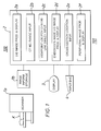
- Figure 1 is a configuration diagram showing an image display apparatus in accordance with a first embodiment of the present invention.
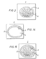
- Figure 2 is a schematic diagram showing a 3D image obtained by the image display apparatus shown in Fig. 1.
- Figure 3 is a flow chart of a procedure in which the image display apparatus shown in Fig. 1 is employed to display an endoscope mode 3D image.
- Figure 4 is a schematic diagram showing a plurality of 2D images on which a 3D image is based.
- Figure 5 is an explanatory diagram illustrating a screen for input of a viewpoint on the 2D image.
- Figure 6 is an explanatory diagram illustrating display of the 3D image by the image display apparatus shown in Fig. 1.
- Figure 7 is an explanatory diagram illustrating the positional relationship between a viewpoint and a cross section.
- Figure 8 is a conceptual diagram illustrating a peripheral image obtained by the image display apparatus shown in Fig. 1.
- Figure 9 is an explanatory diagram illustrating display of the 3D image and the peripheral image by the image display apparatus shown in Fig. 1.
- Figure 10 is an explanatory diagram illustrating display of the 3D image, the peripheral image and a cross-sectional location by the image display apparatus shown in Fig. 1.
- Figure 11 is an explanatory diagram illustrating another display of the 3D image, the peripheral image and a cross-sectional location by the image display apparatus shown in Fig. 1.
- Figure 12 is a configuration diagram showing an image display apparatus in accordance with a second embodiment of the present invention.
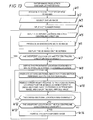
- Figure 13 is a flow chart of a procedure in which the image display apparatus shown in Fig. 12 is employed to display an endoscope mode 3D image.
- Figure 14 is a conceptual diagram illustrating a cross-sectional image obtained by the image display apparatus shown in Fig. 12.
- Figure 15 is a conceptual diagram illustrating a superimposed image obtained by the image display apparatus shown in Fig. 12.
- Figure 16 is a configuration diagram showing an image display apparatus in accordance with a third embodiment of the present invention.
- Figure 17 is a flow chart of a procedure in which the image display apparatus shown in Fig. 16 is employed to display an endoscope mode 3D image.
- Figure 18 is a flow chart continued from the flow chart shown in Fig. 17.
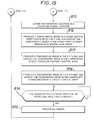
- Figure 19 is another flow chart continued from the flow chart shown in Fig. 17.
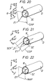
- Figure 20 is an explanatory diagram illustrating a synchro axial plane.
- Figure 21 is an explanatory diagram illustrating a synchro sagittal plane and a synchro coronal plane.
- Figure 22 is an explanatory diagram illustrating a normal axial plane.
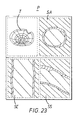
- Figure 23 is a schematic diagram showing the 3D image and reference images obtained by the image display apparatus shown in Fig. 16.
- Figure 1 is a configuration diagram showing an image display apparatus in accordance with a first embodiment of the present invention in combination with image information acquisition means and image information storage means in an X-ray CT apparatus.
- An image display apparatus 101 of the present invention comprises an image processor 2, a display 3 and an input device 4.
- the image processor 2 includes a two-dimensional (2D) image production and display portion 2a, a CT number range input portion 2b, a viewpoint location / field-of-view (FOV) centerline direction input portion 2c, an endoscope mode three-dimensional (3D) image production and display portion 2d, a cross-sectional location input portion 2e and a peripheral image production and display portion 2f.
- 2D two-dimensional
- a scanner 1a scans a patient K at different slice locations (a slice refers to a planar region imaged by tomography) and acquires scan data for a plurality of slices.
- Image storage means 1b stores the scan data.
- the 2D image production and display portion 2a in the image processor 2 processes the scan data for the plurality of slices to generate 2D image data for each slice, and displays a 2D image on the display 3.
- the operator reads from the 2D image a CT number range of the internal body structure (such as ventriculus or blood vessel) of which the endoscope mode 3D image is to be produced, and inputs the CT number range via the input device 4.
- a CT number range of the internal body structure such as ventriculus or blood vessel
- the CT number range input portion 2b in the image processor 2 receives the input CT number range and passes it to the endoscope mode 3D image production and display portion 2d.
- the operator determines a viewpoint location (a virtual endoscope lens position) in the internal space of the internal body tissue and inputs the viewpoint location via the input device 4.
- a FOV centerline direction an optical axis direction of a virtual endoscope lens is also input via the input device 4.
- the viewpoint location / FOV centerline direction input portion 2c in the image processor 2 receives the input viewpoint location and FOV centerline direction and passes them to the endoscope mode 3D image production and display portion 2d.
- the endoscope mode 3D image production and display portion 2d in the image processor 2 extracts from the 2D image data for each slice the pixels within the CT number range in the FOV which extends radially from the viewpoint toward the FOV centerline direction to produce a 3D image as viewing a wall surface of the internal body tissue, and displays the 3D image on the display 3.
- the operator determines a cross-sectional location within a predetermined range lying near the viewpoint location, and inputs the cross-sectional location via the input device 4.
- the cross-sectional location input portion 2e in the image processor 2 receives the input cross-sectional location and passes it to the peripheral image production and display portion 2f.
- the peripheral image production and display portion 2f in the image processor 2 produces a tomographic image of a cross section perpendicular to the FOV centerline at the cross-sectional location based on the 2D image data, and produces a peripheral image (see Fig. 8) obtained by removing the 3D image region from the tomographic image, to display the tomographic image on the display 3.
- Figure 3 is a flow chart of a procedure in which the image display apparatus 101 is employed to display the endoscope mode 3D image .
- Step V1 the patient K is scanned at different slice locations, and data sets for a plurality of sequential 2D images are acquired.
- the sequential 2D images S1 - S7 are illustrated in Fig. 4.
- reference symbol D designates the large intestine.
- Reference symbol K designates the lumen, i.e., the internal space of the large intestine D.
- Each 2D image S1 - S7 is a tomographic image in a plane perpendicular to the z-axis.
- the z-axis is the axis along which the patient K is moved in the scanner 1
- the x-axis is the horizontal axis perpendicular to the z-axis
- the y-axis is the vertical axis perpendicular to the z-axis.
- Step V2 the operator selects an appropriate 2D image from the sequential images using the input device 4.
- the image S5 is selected from among the 2D images S1 - S7.
- Step V3 the operator reads from the selected 2D image a CT number range of the internal body tissue (e.g., the large intestine) of which the endoscope mode 3D image is to be produced, and inputs the CT number range. For example, if the CT number range of the pixels in the large intestine D in the 2D image S5 is "equal to or above 300", "300" is input as the minimum value of the CT number range (and, if necessary, the maximum value may be input).
- Step V4 the operator determines a viewpoint location in the internal space of the internal body tissue and inputs the viewpoint location. For example, as shown in Fig. 5, a cursor U is positioned at a point within the lumen K, the internal space of the large intestine D, and the position is selected.
- the FOV centerline direction is also input. For example, the "depth direction" of the displayed 2D image is specified.
- Step V5 the endoscope mode 3D image production and display portion 2d in the image processor 2 extracts from the 2D image data for each slice the pixels within the CT number range in the FOV which extends radially from the viewpoint toward the FOV centerline direction to produce a 3D image as viewing a wall surface of the internal body tissue.
- the 3D image T shown in Fig. 2 is produced.
- reference symbol A designates a tumor developed on the wall of the large intestine D.
- Step V6 the endoscope mode 3D image production and display portion 2d in the image processor 2 displays the 3D image T in the left screen region GL on the display 3 as shown in Fig. 6.
- Step V7 a check is made whether the operator changed the viewpoint location or the FOV centerline direction. If a change was made, the process returns to Step V5 to update the 3D image; otherwise it goes to Step V8. That is, while the viewpoint location or the FOV centerline direction is being changed, the 3D image continues to be varied according to the change, and when the change is stopped at a certain 3D image, the process goes to Step V8.
- Step V8 the peripheral image production and display portion 2f in the image processor 2 defines the frontmost location contained in the 3D image as a cross-sectional location.
- Step V9 the pixels in a cross section perpendicular to the FOV centerline at the cross-sectional location are extracted from the 2D image data to produce a tomographic image.
- a part of the wall of the large intestine D which is contained in the FOV and lies in the location nearest to the viewpoint El is defined as a cross section Q1, for which a tomographic image is produced.
- the 3D image region is removed from the tomographic image to produce the peripheral image C shown in Fig. 8.
- Step V10 the peripheral image production and display portion 2f in the image processor 2 displays the peripheral image C in the right screen region GR on the display 3 as shown in Fig. 9.
- Step V11 a cross-sectional location indication SL is displayed on the 3D image T as shown in Fig. 10.
- Step V12 a check is made whether the operator changed the cross-sectional location. If a change was made, the process returns to Step V5 to update the peripheral image, and displays the peripheral image in Step V10 and the cross-sectional location indication in Step 11. For example, if the cross-sectional location is moved toward the depth direction, the display as shown in Fig. 11 is formed.
- Step V13 a check is made whether the operator changed the viewpoint location or the FOV centerline direction. If a change was not made, the process returns to Step V12 to maintain the current display; otherwise it goes to Step V14.
- Step V14 the peripheral image C is removed to restore the display as shown in Fig. 6.
- the process then returns to Step V5. That is, when the viewpoint location or the FOV centerline direction was changed, the 3D image T is varied according to the change, and while the 3D image T is being varied, the peripheral image C is not displayed.
- the endoscope mode 3D image T is displayed in the left screen region on the display 3, and the peripheral image C is displayed in the right screen region when the viewpoint is fixed, which enables the surface condition and the internal condition (such as CT numbers of the internal of tissue) of the tumor A to be simultaneously displayed.
- Step V10 the tomographic image may be displayed just as it is. Furthermore, in Step V9, a cross-sectional image of the internal body tissue in a cross section perpendicular to the FOV centerline at the cross-sectional location may be produced based on the 3D data to display the cross-sectional image in Step V10.
- Figure 12 is a configuration diagram showing an image display apparatus in accordance with a second embodiment of the present invention in combination with image information acquisition means and image information storage means in an X-ray CT apparatus.
- the X-ray CT apparatus 200 comprises an image processor 12, a display 3 and an input device 4.
- the image processor 12 includes a 2D image production and display portion 2a, a CT number range input portion 2b, a viewpoint location / FOV centerline direction input portion 2c, an endoscope mode 3D image production and display portion 12d, a cross-sectional location input portion 2e, a cross-sectional image production portion 12f and a superimposed image display portion 12g.
- a scanner 1 scans a patient K at different slice locations and acquires scan data for a plurality of slices.
- the 2D image production and display portion 2a in the image processor 12 processes the scan data for the plurality of slices to generate 2D image data for each slice, and displays a 2D image on the display 3.
- the operator reads from the 2D image a CT number range of the internal body tissue (such as ventriculus or blood vessel) of which the endoscope mode 3D image is to be produced, and inputs the CT number range via the input device 4.
- a CT number range of the internal body tissue such as ventriculus or blood vessel
- the CT number range input portion 2b in the image processor 12 receives the input CT number range and passes it to the endoscope mode 3D image production and display portion 12d.
- the operator determines a viewpoint location in the internal space of the internal body tissue and inputs the viewpoint location via the input device 4.
- the FOV centerline direction is also input via the input device 4.
- the viewpoint location / FOV centerline direction input portion 2c in the image processor 12 receives the input viewpoint location and FOV centerline direction and passes them to the endoscope mode 3D image production and display portion 12d.
- the endoscope mode 3D image production and display portion 12d in the image processor 12 extracts from the 2D image data for each slice the pixels within the CT number range to generate 3D data of the internal body tissue, produces a 3D image (see Fig. 2) representing a wall surface of the internal body tissue as seen in the FOV which extends radially from the viewpoint toward the FOV centerline direction based on the 3D data, and displays the 3D image on the display 3.
- the operator determines a cross-sectional location within a predetermined range lying near the viewpoint location, and inputs the cross-sectional location via the input device 4.
- the cross-sectional location input portion 2e in the image processor 12 receives the input cross-sectional location and passes it to the cross-sectional image production portion 12f.
- the cross-sectional image production portion 12f in the image processor 12 produces a cross-sectional image (see Fig. 14) of the internal body tissue in a cross section perpendicular to the FOV centerline at the cross-sectional location based on the 3D data.
- the superimposed image display portion 12g in the image processor 12 combines the 3D image with the cross-sectional image to display a superimposed image (see Fig. 15) on the screen of the display 3.
- Figure 13 is a flow chart of a procedure in which the image display apparatus 201 is employed to display the endoscope mode 3D image.
- Step W1 the patient K is scanned at different slice locations, and data sets for a plurality of sequential 2D images are acquired.
- the sequential 2D images S1 - S7 are illustrated in Fig. 4.
- reference symbol D designates the large intestine.
- Reference symbol K designates the lumen, i.e., the internal space of the large intestine D.
- Step W2 the operator selects an appropriate 2D image from the sequential images using the input device 4.
- the image S5 is selected from among the 2D images S1 - S7.
- Step W3 the operator reads from the selected 2D image a CT number range of the internal body tissue (e.g., the large intestine D) of which the endoscope mode 3D image is to be produced, and inputs the CT number range. For example, if the CT number range of the pixels in the large intestine D in the 2D image S5 is "equal to or above 300", "300" is input as the minimum value of the CT number range (and, if necessary, the maximum value may be input).
- Step W4 the operator determines a viewpoint location in the internal space of the internal body tissue and inputs the viewpoint location. For example, as shown in Fig. 5, a cursor U is positioned at a point within the lumen K, the internal space of the large intestine D, and the position is selected.
- the FOV centerline direction is also input. For example, the "depth direction" of the displayed 2D image is specified.
- Step W5 the endoscope mode 3D image production and display portion 12d in the image processor 12 extracts from the 2D image data for each slice the pixels within the CT number range to generate 3D data of the internal body tissue, and produces a 3D image representing a wall surface of the internal body tissue as seen in the FOV which extends radially from the viewpoint toward the FOV centerline direction based on the 3D data.
- the 3D image T shown in Fig. 2 is produced.
- reference symbol A designates a tumor developed on the wall of the large intestine D.
- Step W6 the endoscope mode 3D image production and display portion 12d in the image processor 12 displays the 3D image T on the display 3.
- Step W7 a check is made whether the operator changed the viewpoint location or the FOV centerline direction. If a change was made, the process returns to Step W5 to update the 3D image (however, the 3D data need not be regenerated); otherwise it goes to Step W8. That is, while the viewpoint location or the FOV centerline direction is being changed, the 3D image continues to be varied according to the change, and when the change is stopped at a certain 3D image, the process goes to Step W8.
- Step W8 the cross-sectional image production portion 12f in the image processor 12 defines the frontmost location contained in the 3D image as a cross-sectional location.
- Step W9 the pixels in a cross section perpendicular to the FOV centerline at the cross-sectional location are extracted from the 3D data to produce a cross-sectional image.
- the cross-sectional image E shown in Fig. 14 is produced.
- the superimposed image production portion 12g in the image processor 12 removes a front region relative to the cross-sectional location from the 3D image, combines it with the cross-sectional image to produce a superimposed image, and displays the superimposed image I as shown in Fig. 15.
- Step W12 a check is made whether the operator changed the cross-sectional location. If a change was made, the process returns to Step W9 to update the cross-sectional image, and produces and displays the superimposed image in Step W10.
- Step W13 a check is made whether the operator changed the viewpoint location or the FOV centerline direction. If a change was not made, the process returns to Step W12 to maintain the current display; otherwise it goes to Step W14.
- Step W14 the superimposed image I is removed to restore the display as shown in Fig. 6.
- the process then returns to Step W5. That is, when the viewpoint location or the FOV centerline direction was changed, the 3D image T is varied according to the change, and while the 3D image T is being varied, the superimposed image I is not displayed.
- the endoscope mode 3D image T is displayed on the screen of the display 3, and the superimposed image I obtained by combining the 3D image T with the cross-sectional image E is displayed on the screen when the viewpoint is fixed, which enables the surface condition and the internal condition (such as CT numbers) of the tumor A to be simultaneously displayed.
- a tomographic image may be produced in a cross section perpendicular to the FOV centerline at the cross-sectional location based on the 2D image data, and may be combined with the 3D image for display in Step W10.
- 3D volume data may be used.
- Figure 16 is a configuration diagram showing an image display apparatus in accordance with a third embodiment of the present invention in combination with image information acquisition means and image information storage means in an X-ray CT apparatus.
- the image display apparatus 301 comprises an image processor 22, a display 3 and an input device 4.
- the image processor 22 includes a 2D image production and display portion 2a, a CT number range input portion 2b, a viewpoint location / FOV centerline direction / rotational angle input portion 22c, an endoscope mode 3D image production and display portion 2d, a synchro reference image production and display portion 22f and a normal reference image production and display portion 22g.
- normal reference image is meant a reference image based on a coordinate axis assumed to be fixed relative to the image information acquisition means (i.e., the scanner in this embodiment)
- synchro reference image is meant a reference image based on a coordinate axis assumed to be established each time according to a viewpoint location, a FOV centerline direction and a rotational angle specified during endoscope mode imaging.
- a scanner 1 scans a patient K at different slice locations (a slice refers to a planar region imaged by tomography) and acquires scan data for a plurality of slices.
- the 2D image production and display portion 2a in the image processor 22 processes the scan data for the plurality of slices to generate 2D image data for each slice, and displays a 2D image on the display 3.
- the operator reads from the 2D image a CT number range of the internal body tissue (such as ventriculus or blood vessel) of which the endoscope mode 3D image is to be produced, and inputs the CT number range via the input device 4.
- a CT number range of the internal body tissue such as ventriculus or blood vessel
- the CT number range input portion 2b in the image processor 22 receives the input CT number range and passes it to the endoscope mode 3D image production and display portion 2d.
- the operator determines a viewpoint location (a virtual endoscope lens position) in the internal space of the internal body tissue and inputs the viewpoint location via the input device 4.
- a FOV centerline direction an optical axis direction of a virtual endoscope lens
- a rotational angle is input via the input device 4.
- the rotational angle represents a rotational angle around a pivot of the endoscope.
- the viewpoint location / FOV centerline direction / rotational angle input portion 22c in the image processor 22 receives the input viewpoint location, FOV centerline direction and rotational angle, and passes them to the endoscope mode 3D image production and display portion 2d.
- the endoscope mode 3D image production and display portion 2d in the image processor 22 extracts from the 2D image data for each slice the pixels within the CT number range in the FOV which extends radially from the viewpoint location toward the FOV centerline direction to produce a 3D image as viewing a wall surface of the internal body tissue, and displays the 3D image on the display 3.
- the orientation of the display of the 3D image is determined so that the spatial direction corresponding to the rotational angle coincides with the screen vertical axis.
- the operator specifies and inputs via the input device 4 which of the normal reference image and the synchro reference image is to be displayed as a reference image.
- the normal reference image production and display portion 22g in the image processor 22 produces a tomographic image in a plane parallel to the x-y plane shown in Fig. 4 and passing through the viewpoint location based on the 2D image data, and displays the image as a normal axial image.
- the normal reference image production and display portion 22f also produces a tomographic image in a plane parallel to the z-y plane shown in Fig. 4 and passing through the viewpoint location, and displays the image as a normal sagittal image.
- the normal reference image production and display portion 22f produces a tomographic image in a plane parallel to the z-x plane shown in Fig. 4 and passing through the viewpoint location, and displays the image as a normal coronal image.
- the synchro reference image production and display portion 22f in the image processor 22 produces a tomographic image in a plane perpendicular to the FOV centerline and passing through the viewpoint location (SAP in Fig. 20) based on the 2D image data, and displays the image as a synchro axial image (SA in Fig. 23).
- the synchro reference image production and display portion 22g also produces a tomographic image in a plane parallel to the spatial axis which corresponds to the screen vertical axis of the display 3 displaying the 3D image, and containing the viewpoint location and the FOV centerline (SSP in Fig. 21), and displays the image as a synchro sagittal image (SS in Fig.
- the synchro reference image production and display portion 22g produces a tomographic image in a plane parallel to the spatial axis which corresponds to the screen horizontal axis of the display 3 displaying the 3D image, and containing the viewpoint location and the FOV centerline (SCP in Fig. 21), and displays the image as a synchro coronal image (SC in Fig. 23).
- Figures 17 - 19 are flow charts of a procedure in which the image display apparatus 301 is employed to display the endoscope mode 3D image.
- Step R1 the patient K is scanned at different slice locations, and data sets for a plurality of sequential 2D images are acquired.
- the sequential 2D images S1 - S7 are illustrated in Fig. 4.
- reference symbol D designates the large intestine.
- Reference symbol K designates the lumen, i.e., the internal space of the large intestine D.
- Each 2D image S1 - S7 is a tomographic image in a plane perpendicular to the z-axis.
- the z-axis is the axis along which the patient K is moved in the scanner 1
- the x-axis is the horizontal axis perpendicular to the z-axis
- the y-axis is the vertical axis perpendicular to the z-axis.
- Step R2 the operator selects an appropriate 2D image from the sequential images using the input device 4.
- the image S5 is selected from among the 2D images S1 - S7.
- Step R3 the operator reads from the selected 2D image a CT number range of the internal body tissue (e.g., the large intestine D) of which the endoscope mode 3D image is to be produced, and inputs the CT number range. For example, if the CT number range of the pixels in the large intestine D in the 2D image S5 is "equal to or above 300", "300" is input as the minimum value of the CT number range (and, if necessary, the maximum value may be input).
- Step R4 the operator determines a viewpoint location in the internal space of the internal body tissue and inputs the viewpoint location. For example, as shown in Fig. 5, a cursor U is positioned at a point within the lumen K, the internal space of the large intestine D, on the 2D image S5, and the position is selected.
- the FOV centerline direction and the rotational angle are also input. For example, if the home position is input via a keyboard of the input device 4, the FOV centerline direction is +z direction and the rotational angle is 0°. Furthermore, if a track ball in the input device 4 is rotated, the FOV centerline direction and the rotational angle can be rotated to establish a coordinate axis corresponding to the endoscope mode.
- Step R5 the endoscope mode 3D image production and display portion 2d in the image processor 22 extracts from the 2D image data for each slice the pixels within the CT number range in the FOV which extends radially from the viewpoint toward the FOV centerline direction to produce a 3D image as viewing a wall surface of the internal body tissue.
- Step R6 the endoscope mode 3D image production and display portion 2d in the image processor 22 displays a 3D image T in the upper-left screen region with a display orientation such that a spatial direction corresponding to the rotational angle coincides with the axis perpendicular to the display screen, as shown in Fig. 23.
- Step R7 a check is made whether the operator changed the viewpoint location, the FOV centerline direction or the rotational angle. If a change was made, the process returns to Step R5 to update the 3D image; otherwise it goes to Step R8. That is, while the viewpoint location, the FOV centerline direction or the rotational angle is being changed, the 3D image continues to be varied according to the change, and when the change is stopped at a certain 3D image, the process goes to Step R8.
- Step R8 a check is made whether the operator specified the synchro reference image as a reference image. If so specified, the process goes to Step R9 in Fig. 18, otherwise to Step R15 in Fig. 19.
- Step R9 in Fig. 18 the synchro reference image production and display portion 22f in the image processor 22 defines the viewpoint location as a cross-sectional location.
- Step R10 the synchro reference image production and display portion 22f extracts from the 2D image data the pixels in the synchro axial plane SAP perpendicular to the FOV centerline SC and containing the viewpoint El as shown in Fig. 20 to produce a tomographic image, and displays the image in the upper-right screen region as a synchro axial image SA as shown in Fig. 23.
- Figure 20 illustrates the relationship among the internal body tissue (i.e., the large intestine in this example) which is an object for image display, the coordinate system (x, y, z) assumed to be fixed relative to the image information acquisition means, and the coordinate systems (x', y', z') and (X', Y', z') established each time the endoscope mode is executed.
- the coordinate system (x, y, z) assumed to be fixed relative to the image information acquisition means
- the coordinate systems (x', y', z') and (X', Y', z') established each time the endoscope mode is executed.
- the z'-axis is a coordinate axis parallel to the FOV center axis SC.
- the Y'-axis is an axis which is contained within the z-y plane and perpendicular to the z'-axis
- the y'-axis is an axis which is formed by rotating the Y'-axis by the rotational angle ⁇ around the z'-axis.
- the X'-axis is an axis which is perpendicular to the z'-axis and the Y'-axis
- the x'-axis is an axis which is perpendicular to the z'-axis and the y'-axis.
- the synchro reference image production and display portion 22f extracts from the 2D image data the pixels in the synchro sagittal plane SSP parallel to the z'-y' plane and containing the viewpoint El as shown in Fig. 21 to produce a tomographic image, and displays the image in the lower-right screen region as a synchro sagittal image SS as shown in Fig. 23.
- the synchro reference image production and display portion 22f extracts from the 2D image data the pixels in the synchro coronal plane SCP parallel to the z'-x' plane and containing the viewpoint El as shown in Fig. 21 to produce a tomographic image, and displays the image in the lower-left screen region as a synchro coronal image SC as shown in Fig. 23.
- Step R13 a check is made whether the operator changed the viewpoint location, the FOV centerline direction or the rotational angle. If a change was made, the process goes to Step R14; otherwise it maintains the current display.
- Step R14 all of the images are removed, and the process returns to Step R5 in Fig. 17.
- Step R8 in Fig. 17 the normal reference image production and display portion 22g in the image processor 22 defines the visual position as a cross-sectional location in Step R15 in Fig. 19.
- Step R16 the normal reference image production and display portion 22g extracts from the 2D image data the pixels in the normal axial plane NAP perpendicular to the z-axis and containing the viewpoint El as shown in Fig. 22 to produce a tomographic image, and displays the image in the upper-right screen region as a normal axial image.
- the normal reference image production and display portion 22g extracts from the 2D image data the pixels in a plane parallel to the z-y plane and containing the viewpoint E1 to produce a tomographic image, and displays the image in the lower-right screen region as a normal sagittal image.
- Step R18 the normal reference image production and display portion 22g extracts from the 2D image data the pixels in a plane parallel to the z-x plane and containing the viewpoint El to produce a tomographic image, and displays the image in the lower-left screen region as a normal coronal image.
- Step R19 a check is made whether the operator changed the viewpoint location, the FOV centerline direction or the rotational angle. If a change was made, the process goes to Step R20; otherwise it maintains the current display.
- Step R20 all of the images are removed, and the process returns to Step R5 in Fig. 17.
- the endoscope mode 3D image T is displayed on the screen of the display 3, and the reference images are displayed in the other screen regions when the viewpoint is fixed. This enables the operator to spatially recognize the current FOV centerline direction clearly.
- the image display apparatus of the present invention can be operated separately from the image information acquisition means so long as the image display apparatus is placed under circumstances in which the apparatus can access systematically stored image information.
- the image information on the human internal body tissue may be acquired by any other means, such as an MRI (magnetic resonance imaging) apparatus.
- MRI magnetic resonance imaging
- image information acquisition means and the image information storage means are described as being conceptually separated, they can also be understood to be included in an image diagnostic apparatus system, such as an X-ray CT apparatus or an MRI apparatus.
- a step for inputting the CT value as a parameter representing the image signal intensity is included in the image display process, but what should be input as such a parameter may be appropriately selected according to the image information acquisition means employed, including whether the step for inputting such a parameter is to be included in the process.
- large intestine tissue is cited as an object to be displayed in the description of the above embodiments, but the image display method in accordance with the present invention applies suitably to any other tissue which may have a cavity therein, such as small intestine, stomach, esophagus, trachea, urethra, vagina, uterus or oviduct.
Landscapes
- Engineering & Computer Science (AREA)
- Health & Medical Sciences (AREA)
- Life Sciences & Earth Sciences (AREA)
- Medical Informatics (AREA)
- Physics & Mathematics (AREA)
- Molecular Biology (AREA)
- Public Health (AREA)
- Biophysics (AREA)
- Nuclear Medicine, Radiotherapy & Molecular Imaging (AREA)
- Optics & Photonics (AREA)
- Pathology (AREA)
- Radiology & Medical Imaging (AREA)
- Biomedical Technology (AREA)
- Heart & Thoracic Surgery (AREA)
- Veterinary Medicine (AREA)
- Surgery (AREA)
- Animal Behavior & Ethology (AREA)
- General Health & Medical Sciences (AREA)
- High Energy & Nuclear Physics (AREA)
- Theoretical Computer Science (AREA)
- Human Computer Interaction (AREA)
- Computer Vision & Pattern Recognition (AREA)
- Computer Graphics (AREA)
- Computer Hardware Design (AREA)
- General Engineering & Computer Science (AREA)
- Software Systems (AREA)
- General Physics & Mathematics (AREA)
- Pulmonology (AREA)
- Apparatus For Radiation Diagnosis (AREA)
- Measuring And Recording Apparatus For Diagnosis (AREA)
Applications Claiming Priority (3)
| Application Number | Priority Date | Filing Date | Title |
|---|---|---|---|
| JP230039/97 | 1997-08-26 | ||
| JP09230039A JP3117665B2 (ja) | 1997-08-26 | 1997-08-26 | 画像表示方法および画像表示装置 |
| JP23003997 | 1997-08-26 |
Publications (3)
| Publication Number | Publication Date |
|---|---|
| EP0899693A2 true EP0899693A2 (de) | 1999-03-03 |
| EP0899693A3 EP0899693A3 (de) | 2003-06-25 |
| EP0899693B1 EP0899693B1 (de) | 2007-11-14 |
Family
ID=16901616
Family Applications (1)
| Application Number | Title | Priority Date | Filing Date |
|---|---|---|---|
| EP98306843A Expired - Lifetime EP0899693B1 (de) | 1997-08-26 | 1998-08-26 | Bildanzeigevorrichtung und Verfahren |
Country Status (6)
| Country | Link |
|---|---|
| US (1) | US6252599B1 (de) |
| EP (1) | EP0899693B1 (de) |
| JP (1) | JP3117665B2 (de) |
| KR (2) | KR100327812B1 (de) |
| DE (1) | DE69838698T2 (de) |
| TW (1) | TW390802B (de) |
Cited By (4)
| Publication number | Priority date | Publication date | Assignee | Title |
|---|---|---|---|---|
| EP0981109A3 (de) * | 1998-08-14 | 2004-01-14 | Ge Yokogawa Medical Systems, Ltd. | Bildanzeigungs-Verfahren und Gerät |
| CN101088464B (zh) * | 2006-06-15 | 2011-05-25 | Ge医疗系统环球技术有限公司 | 成像设备和成像方法 |
| US8285012B2 (en) | 2005-04-28 | 2012-10-09 | Hitachi Medical Corporation | Image display apparatus and program |
| EP2157546A3 (de) * | 2008-08-18 | 2014-03-26 | Kabushiki Kaisha Toshiba | Vorrichtung zur Verarbeitung medizinischer Bilder, Ultraschallbildgebungsvorrichtung, Röntgen-CT-Vorrichtung (Röntgen-Computertomographievorrichtung) und Verfahren zur Verarbeitung medizinischer Bilder |
Families Citing this family (35)
| Publication number | Priority date | Publication date | Assignee | Title |
|---|---|---|---|---|
| SE509524C2 (sv) | 1997-06-04 | 1999-02-08 | Volvo Lastvagnar Ab | Förbränningsmotor med AT-regulator |
| KR100346363B1 (ko) * | 2000-06-02 | 2002-08-01 | 주식회사 엔지티 | 자동 의료 영상 분할을 통한 3차원 영상 데이터 구축방법/장치, 및 그를 이용한 영상유도 수술 장치 |
| JP5361103B2 (ja) * | 2000-10-24 | 2013-12-04 | 株式会社東芝 | 画像処理装置 |
| US7095401B2 (en) * | 2000-11-02 | 2006-08-22 | Siemens Corporate Research, Inc. | System and method for gesture interface |
| JP2003167659A (ja) * | 2001-11-28 | 2003-06-13 | Fujitsu Ltd | 情報処理装置および情報オブジェクトの表示方法 |
| US6892090B2 (en) * | 2002-08-19 | 2005-05-10 | Surgical Navigation Technologies, Inc. | Method and apparatus for virtual endoscopy |
| EP1781175B1 (de) * | 2004-08-17 | 2019-05-01 | Koninklijke Philips N.V. | System und verfahren für flexible 3dra-ct-fusion |
| JP4130428B2 (ja) * | 2004-09-02 | 2008-08-06 | ザイオソフト株式会社 | 画像処理方法及び画像処理プログラム |
| KR100702148B1 (ko) * | 2004-12-30 | 2007-03-30 | 한국전기연구원 | 단층영상과 입체 표면영상을 동시에 얻을 수 있는 엑스선단층 촬영장치 |
| JP4694435B2 (ja) * | 2005-07-29 | 2011-06-08 | 株式会社竹中工務店 | 断面画像表示装置、断面画像表示方法及び断面画像表示プログラム |
| JP2008000270A (ja) * | 2006-06-21 | 2008-01-10 | Aze Ltd | 生体組織の識別画像作成方法、装置およびプログラム |
| US20080086051A1 (en) * | 2006-09-20 | 2008-04-10 | Ethicon Endo-Surgery, Inc. | System, storage medium for a computer program, and method for displaying medical images |
| US8457718B2 (en) * | 2007-03-21 | 2013-06-04 | Ethicon Endo-Surgery, Inc. | Recognizing a real world fiducial in a patient image data |
| US20080319307A1 (en) * | 2007-06-19 | 2008-12-25 | Ethicon Endo-Surgery, Inc. | Method for medical imaging using fluorescent nanoparticles |
| US8155728B2 (en) * | 2007-08-22 | 2012-04-10 | Ethicon Endo-Surgery, Inc. | Medical system, method, and storage medium concerning a natural orifice transluminal medical procedure |
| US20080221434A1 (en) * | 2007-03-09 | 2008-09-11 | Voegele James W | Displaying an internal image of a body lumen of a patient |
| US20080234544A1 (en) * | 2007-03-20 | 2008-09-25 | Ethicon Endo-Sugery, Inc. | Displaying images interior and exterior to a body lumen of a patient |
| US8081810B2 (en) * | 2007-03-22 | 2011-12-20 | Ethicon Endo-Surgery, Inc. | Recognizing a real world fiducial in image data of a patient |
| JP5283877B2 (ja) * | 2007-09-21 | 2013-09-04 | 株式会社東芝 | 超音波診断装置 |
| JP2009240621A (ja) * | 2008-03-31 | 2009-10-22 | Hoya Corp | 内視鏡装置 |
| JP5392644B2 (ja) * | 2008-06-13 | 2014-01-22 | 株式会社日立メディコ | 画像表示装置、方法、及びプログラム |
| JP5433240B2 (ja) * | 2009-01-21 | 2014-03-05 | 株式会社東芝 | 超音波診断装置及び画像表示装置 |
| JP5395538B2 (ja) * | 2009-06-30 | 2014-01-22 | 株式会社東芝 | 超音波診断装置及び画像データ表示用制御プログラム |
| JP5523784B2 (ja) * | 2009-09-30 | 2014-06-18 | 株式会社東芝 | 画像処理装置および医用画像診断装置 |
| JP5631584B2 (ja) * | 2009-12-25 | 2014-11-26 | 株式会社東芝 | 医用画像処理装置、医用画像処理プログラム及び医用画像診断装置 |
| JP2012040081A (ja) * | 2010-08-17 | 2012-03-01 | Toshiba Corp | 医用画像処理装置、及び医用画像処理プログラム |
| JP2012040207A (ja) * | 2010-08-19 | 2012-03-01 | Toshiba Corp | 超音波診断装置、超音波診断装置の制御プログラム、及び画像処理装置 |
| JP5309109B2 (ja) | 2010-10-18 | 2013-10-09 | 富士フイルム株式会社 | 医用画像処理装置および方法、並びにプログラム |
| JP6266217B2 (ja) * | 2012-04-02 | 2018-01-24 | 東芝メディカルシステムズ株式会社 | 医用画像処理システム、方法及びプログラム |
| US9741166B2 (en) * | 2012-11-24 | 2017-08-22 | Novarad Corporation | Generation and viewing of panoramic images |
| US10510171B2 (en) * | 2016-11-29 | 2019-12-17 | Biosense Webster (Israel) Ltd. | Visualization of anatomical cavities |
| US10499997B2 (en) | 2017-01-03 | 2019-12-10 | Mako Surgical Corp. | Systems and methods for surgical navigation |
| US10506991B2 (en) | 2017-08-31 | 2019-12-17 | Biosense Webster (Israel) Ltd. | Displaying position and optical axis of an endoscope in an anatomical image |
| JP2022135392A (ja) * | 2021-03-05 | 2022-09-15 | コニカミノルタ株式会社 | 医用情報管理装置、医用情報管理方法および医用情報管理プログラム |
| WO2024028925A1 (ja) | 2022-08-01 | 2024-02-08 | 日本電気株式会社 | 内視鏡検査支援装置、内視鏡検査支援方法、及び、記録媒体 |
Family Cites Families (7)
| Publication number | Priority date | Publication date | Assignee | Title |
|---|---|---|---|---|
| US5608849A (en) * | 1991-08-27 | 1997-03-04 | King, Jr.; Donald | Method of visual guidance for positioning images or data in three-dimensional space |
| WO1995035139A1 (en) * | 1994-06-17 | 1995-12-28 | Namco Ltd. | Three-dimensional simulator and image generating method |
| US5920319A (en) * | 1994-10-27 | 1999-07-06 | Wake Forest University | Automatic analysis in virtual endoscopy |
| US5963209A (en) * | 1996-01-11 | 1999-10-05 | Microsoft Corporation | Encoding and progressive transmission of progressive meshes |
| US6009188A (en) * | 1996-02-16 | 1999-12-28 | Microsoft Corporation | Method and system for digital plenoptic imaging |
| JPH1031761A (ja) * | 1996-07-17 | 1998-02-03 | Ge Yokogawa Medical Syst Ltd | 画像表示方法および画像表示装置 |
| US5990900A (en) * | 1997-12-24 | 1999-11-23 | Be There Now, Inc. | Two-dimensional to three-dimensional image converting system |
-
1997
- 1997-08-26 JP JP09230039A patent/JP3117665B2/ja not_active Expired - Fee Related
-
1998
- 1998-05-16 US US09/080,176 patent/US6252599B1/en not_active Expired - Lifetime
- 1998-07-15 KR KR1019980028533A patent/KR100327812B1/ko not_active Expired - Fee Related
- 1998-08-13 TW TW087113333A patent/TW390802B/zh not_active IP Right Cessation
- 1998-08-26 DE DE69838698T patent/DE69838698T2/de not_active Expired - Lifetime
- 1998-08-26 EP EP98306843A patent/EP0899693B1/de not_active Expired - Lifetime
-
2001
- 2001-05-31 KR KR1020010030359A patent/KR100340773B1/ko not_active Expired - Fee Related
Cited By (4)
| Publication number | Priority date | Publication date | Assignee | Title |
|---|---|---|---|---|
| EP0981109A3 (de) * | 1998-08-14 | 2004-01-14 | Ge Yokogawa Medical Systems, Ltd. | Bildanzeigungs-Verfahren und Gerät |
| US8285012B2 (en) | 2005-04-28 | 2012-10-09 | Hitachi Medical Corporation | Image display apparatus and program |
| CN101088464B (zh) * | 2006-06-15 | 2011-05-25 | Ge医疗系统环球技术有限公司 | 成像设备和成像方法 |
| EP2157546A3 (de) * | 2008-08-18 | 2014-03-26 | Kabushiki Kaisha Toshiba | Vorrichtung zur Verarbeitung medizinischer Bilder, Ultraschallbildgebungsvorrichtung, Röntgen-CT-Vorrichtung (Röntgen-Computertomographievorrichtung) und Verfahren zur Verarbeitung medizinischer Bilder |
Also Published As
| Publication number | Publication date |
|---|---|
| KR100327812B1 (ko) | 2002-04-17 |
| DE69838698D1 (de) | 2007-12-27 |
| DE69838698T2 (de) | 2008-09-25 |
| EP0899693A3 (de) | 2003-06-25 |
| KR19990023201A (ko) | 1999-03-25 |
| JPH1156832A (ja) | 1999-03-02 |
| US6252599B1 (en) | 2001-06-26 |
| TW390802B (en) | 2000-05-21 |
| EP0899693B1 (de) | 2007-11-14 |
| KR100340773B1 (ko) | 2002-06-20 |
| KR20010078402A (ko) | 2001-08-20 |
| JP3117665B2 (ja) | 2000-12-18 |
Similar Documents
| Publication | Publication Date | Title |
|---|---|---|
| EP0899693B1 (de) | Bildanzeigevorrichtung und Verfahren | |
| JP4421016B2 (ja) | 医用画像処理装置 | |
| US6456735B1 (en) | Image display method and apparatus | |
| US5229935A (en) | 3-dimensional image display apparatus capable of displaying a 3-D image by manipulating a positioning encoder | |
| EP0216156B1 (de) | Kubusteilungssystem und Verfahren zur Anzeige von im Innengebiet eines massiven Körpers enthaltenen Flächenstrukturen | |
| US5526812A (en) | Display system for enhancing visualization of body structures during medical procedures | |
| US5261404A (en) | Three-dimensional mammal anatomy imaging system and method | |
| EP0646263B1 (de) | Graphisches digitalverarbeitungssystem und echtzeitvideosystem zur verbesserung der darstellung von körperstrukturen während eines chirugischen eingriffs. | |
| US6768496B2 (en) | System and method for generating an image from an image dataset and a video image | |
| US6990231B2 (en) | Method and apparatus for forming and displaying projection image from a plurality of sectional images | |
| CA2003497C (en) | Probe-correlated viewing of anatomical image data | |
| EP0791894A3 (de) | System und Verfahren zur Anzeige von windschiefen Schnittebenen im Innern eines massiven Körpers | |
| JPH04183446A (ja) | 画像合成による手術支援システム | |
| EP2483865A1 (de) | Medizinisches bildanalysesystem für deformierte anatomische bilder und zugehörige verfahren | |
| US5514962A (en) | Oblique MR image controlled from a 3D workstation model | |
| EP0629963A2 (de) | Anzeigesystem zur Darstellung von Körperteilen während medizinischen Verfahren | |
| JPH0838433A (ja) | 医用画像診断装置 | |
| US6429862B1 (en) | Three-dimensional image processing apparatus | |
| JPH08161520A (ja) | 三次元画像の対象部分抽出方法 | |
| JPH1031761A (ja) | 画像表示方法および画像表示装置 | |
| JP2001076184A (ja) | 3次元表示方法および3次元表示装置 | |
| WO1991014397A1 (en) | Three-dimensional graphics simulation and actual imaging data composite display | |
| JPH08280710A (ja) | 実時間医用装置及び患者に医用手順を遂行するために操作者を支援する方法 | |
| Zamorano et al. | 3D 2D Multiplanar Stereotactic Planning System: Hardware And Software Configuration | |
| JP2007014483A (ja) | 医用診断装置及び診断支援装置 |
Legal Events
| Date | Code | Title | Description |
|---|---|---|---|
| PUAI | Public reference made under article 153(3) epc to a published international application that has entered the european phase |
Free format text: ORIGINAL CODE: 0009012 |
|
| AK | Designated contracting states |
Kind code of ref document: A2 Designated state(s): AT BE CH CY DE DK ES FI FR GB GR IE IT LI LU MC NL PT SE |
|
| AX | Request for extension of the european patent |
Free format text: AL;LT;LV;MK;RO;SI |
|
| PUAL | Search report despatched |
Free format text: ORIGINAL CODE: 0009013 |
|
| AK | Designated contracting states |
Designated state(s): AT BE CH CY DE DK ES FI FR GB GR IE IT LI LU MC NL PT SE |
|
| AX | Request for extension of the european patent |
Extension state: AL LT LV MK RO SI |
|
| 17P | Request for examination filed |
Effective date: 20031229 |
|
| AKX | Designation fees paid |
Designated state(s): DE FR GB |
|
| 17Q | First examination report despatched |
Effective date: 20041213 |
|
| GRAP | Despatch of communication of intention to grant a patent |
Free format text: ORIGINAL CODE: EPIDOSNIGR1 |
|
| GRAS | Grant fee paid |
Free format text: ORIGINAL CODE: EPIDOSNIGR3 |
|
| GRAA | (expected) grant |
Free format text: ORIGINAL CODE: 0009210 |
|
| AK | Designated contracting states |
Kind code of ref document: B1 Designated state(s): DE FR GB |
|
| REG | Reference to a national code |
Ref country code: GB Ref legal event code: FG4D |
|
| REF | Corresponds to: |
Ref document number: 69838698 Country of ref document: DE Date of ref document: 20071227 Kind code of ref document: P |
|
| ET | Fr: translation filed | ||
| PLBE | No opposition filed within time limit |
Free format text: ORIGINAL CODE: 0009261 |
|
| STAA | Information on the status of an ep patent application or granted ep patent |
Free format text: STATUS: NO OPPOSITION FILED WITHIN TIME LIMIT |
|
| 26N | No opposition filed |
Effective date: 20080815 |
|
| GBPC | Gb: european patent ceased through non-payment of renewal fee |
Effective date: 20080826 |
|
| REG | Reference to a national code |
Ref country code: FR Ref legal event code: ST Effective date: 20090430 |
|
| PG25 | Lapsed in a contracting state [announced via postgrant information from national office to epo] |
Ref country code: FR Free format text: LAPSE BECAUSE OF NON-PAYMENT OF DUE FEES Effective date: 20080901 |
|
| PG25 | Lapsed in a contracting state [announced via postgrant information from national office to epo] |
Ref country code: GB Free format text: LAPSE BECAUSE OF NON-PAYMENT OF DUE FEES Effective date: 20080826 |
|
| PGFP | Annual fee paid to national office [announced via postgrant information from national office to epo] |
Ref country code: DE Payment date: 20150827 Year of fee payment: 18 |
|
| REG | Reference to a national code |
Ref country code: DE Ref legal event code: R119 Ref document number: 69838698 Country of ref document: DE |
|
| PG25 | Lapsed in a contracting state [announced via postgrant information from national office to epo] |
Ref country code: DE Free format text: LAPSE BECAUSE OF NON-PAYMENT OF DUE FEES Effective date: 20170301 |