EP0899461B2 - Pompe immergée avec une conduit de décharge rigide - Google Patents
Pompe immergée avec une conduit de décharge rigide Download PDFInfo
- Publication number
- EP0899461B2 EP0899461B2 EP98113238A EP98113238A EP0899461B2 EP 0899461 B2 EP0899461 B2 EP 0899461B2 EP 98113238 A EP98113238 A EP 98113238A EP 98113238 A EP98113238 A EP 98113238A EP 0899461 B2 EP0899461 B2 EP 0899461B2
- Authority
- EP
- European Patent Office
- Prior art keywords
- liquid
- pipe
- submersible pump
- duct unit
- pipe segment
- Prior art date
- Legal status (The legal status is an assumption and is not a legal conclusion. Google has not performed a legal analysis and makes no representation as to the accuracy of the status listed.)
- Expired - Lifetime
Links
- 230000008878 coupling Effects 0.000 claims abstract description 8
- 238000010168 coupling process Methods 0.000 claims abstract description 8
- 238000005859 coupling reaction Methods 0.000 claims abstract description 8
- 229910052782 aluminium Inorganic materials 0.000 claims abstract description 6
- XAGFODPZIPBFFR-UHFFFAOYSA-N aluminium Chemical compound [Al] XAGFODPZIPBFFR-UHFFFAOYSA-N 0.000 claims abstract description 6
- 229910052751 metal Inorganic materials 0.000 claims abstract 2
- 239000002184 metal Substances 0.000 claims abstract 2
- 239000007788 liquid Substances 0.000 claims description 79
- 238000007789 sealing Methods 0.000 claims description 6
- 238000005452 bending Methods 0.000 claims description 2
- 239000004411 aluminium Substances 0.000 claims 1
- XLYOFNOQVPJJNP-UHFFFAOYSA-N water Substances O XLYOFNOQVPJJNP-UHFFFAOYSA-N 0.000 description 15
- 238000004519 manufacturing process Methods 0.000 description 5
- 239000012530 fluid Substances 0.000 description 4
- 238000005086 pumping Methods 0.000 description 3
- XEEYBQQBJWHFJM-UHFFFAOYSA-N Iron Chemical compound [Fe] XEEYBQQBJWHFJM-UHFFFAOYSA-N 0.000 description 2
- 230000000712 assembly Effects 0.000 description 2
- 238000000429 assembly Methods 0.000 description 2
- 238000009434 installation Methods 0.000 description 2
- 230000002262 irrigation Effects 0.000 description 2
- 238000003973 irrigation Methods 0.000 description 2
- 239000000463 material Substances 0.000 description 2
- 238000005096 rolling process Methods 0.000 description 2
- 238000003892 spreading Methods 0.000 description 2
- XQTLDIFVVHJORV-UHFFFAOYSA-N tecnazene Chemical compound [O-][N+](=O)C1=C(Cl)C(Cl)=CC(Cl)=C1Cl XQTLDIFVVHJORV-UHFFFAOYSA-N 0.000 description 2
- 238000003809 water extraction Methods 0.000 description 2
- 241001166076 Diapheromera femorata Species 0.000 description 1
- 238000004140 cleaning Methods 0.000 description 1
- 230000007797 corrosion Effects 0.000 description 1
- 238000005260 corrosion Methods 0.000 description 1
- 238000006073 displacement reaction Methods 0.000 description 1
- 230000000694 effects Effects 0.000 description 1
- 238000000605 extraction Methods 0.000 description 1
- 230000002550 fecal effect Effects 0.000 description 1
- 230000037431 insertion Effects 0.000 description 1
- 238000003780 insertion Methods 0.000 description 1
- 229910052742 iron Inorganic materials 0.000 description 1
- 210000002445 nipple Anatomy 0.000 description 1
- 238000003825 pressing Methods 0.000 description 1
- 230000000284 resting effect Effects 0.000 description 1
- 239000000725 suspension Substances 0.000 description 1
Images
Classifications
-
- F—MECHANICAL ENGINEERING; LIGHTING; HEATING; WEAPONS; BLASTING
- F04—POSITIVE - DISPLACEMENT MACHINES FOR LIQUIDS; PUMPS FOR LIQUIDS OR ELASTIC FLUIDS
- F04D—NON-POSITIVE-DISPLACEMENT PUMPS
- F04D29/00—Details, component parts, or accessories
- F04D29/40—Casings; Connections of working fluid
- F04D29/406—Casings; Connections of working fluid especially adapted for liquid pumps
-
- F—MECHANICAL ENGINEERING; LIGHTING; HEATING; WEAPONS; BLASTING
- F04—POSITIVE - DISPLACEMENT MACHINES FOR LIQUIDS; PUMPS FOR LIQUIDS OR ELASTIC FLUIDS
- F04D—NON-POSITIVE-DISPLACEMENT PUMPS
- F04D13/00—Pumping installations or systems
- F04D13/02—Units comprising pumps and their driving means
- F04D13/06—Units comprising pumps and their driving means the pump being electrically driven
- F04D13/08—Units comprising pumps and their driving means the pump being electrically driven for submerged use
-
- F—MECHANICAL ENGINEERING; LIGHTING; HEATING; WEAPONS; BLASTING
- F16—ENGINEERING ELEMENTS AND UNITS; GENERAL MEASURES FOR PRODUCING AND MAINTAINING EFFECTIVE FUNCTIONING OF MACHINES OR INSTALLATIONS; THERMAL INSULATION IN GENERAL
- F16L—PIPES; JOINTS OR FITTINGS FOR PIPES; SUPPORTS FOR PIPES, CABLES OR PROTECTIVE TUBING; MEANS FOR THERMAL INSULATION IN GENERAL
- F16L27/00—Adjustable joints; Joints allowing movement
- F16L27/12—Adjustable joints; Joints allowing movement allowing substantial longitudinal adjustment or movement
- F16L27/127—Adjustable joints; Joints allowing movement allowing substantial longitudinal adjustment or movement with means for locking the longitudinal adjustment or movement in the final mounted position
- F16L27/1274—Adjustable joints; Joints allowing movement allowing substantial longitudinal adjustment or movement with means for locking the longitudinal adjustment or movement in the final mounted position by means of a swivel nut
Definitions
- the invention relates to a device for conducting a liquid from a submersible pump immersed at least partially into the liquid to a liquid dispenser which can be arranged outside the liquid, according to the preamble of claim 1 and to a submersible pump arrangement according to the preamble of claim 12
- Submersible pumps are suitable for underwater operation suitable liquid pumps, which are used for example in the context of garden irrigation to promote collected rainwater from wells, ponds or rainwater collection containers. They are also suitable, for example, for pumping out flooded cellars or the like. As a rule, submersible pumps are completely submerged, normally standing on the liquid-coated floor and sucking in the liquid through intake openings near the floor. The liquid is then discharged through a liquid outlet, which is also usually below the liquid surface.
- a hose For directing the conveyed liquid out of the liquid, it is known to connect a hose to a remplisstechniksauslisterstutzen the submersible pump housing, for example via a hose quick coupling.
- the hose is normally mounted before lowering the submersible pump in the liquid at the liquid outlet and forms with its end facing away from the pump a liquid output to which, for example, a syringe, a shower, a sprinkler or irrigation system can be connected.
- a rigid tube can be rigidly and removably attached as a conduit unit.
- An example is shown in US-A-3,085,513.
- the made of iron or copper-de tube is shaped so that its end protrudes beyond the edge of a container into which the submersible pump is inserted.
- a telescopic nozzle tube is provided to produce a fountain fountain. Only the nozzle at the upper end of the nozzle tube protrudes over a water level, while at the lower end of the nozzle tube a branch wrap is envisaged.
- the invention has as its object to provide a device for guiding a pumped by a submersible liquid, which allows a convenient operation and a more efficient use of submersible pump assemblies, especially in the garden area.
- the invention proposes a device with the features of claim 1.
- a rigid pipe unit for guiding the conveyed by the submersible liquid for liquid delivery, which is designed for rigid connection with the submersible pump.
- the detachable connected to the submersible pump, rigid line unit forms after connection to the submersible pump with this submersible Anordnüng that is dimensionally stable and in which the liquid output is in geometrically fixed relationship to the submersible pump.
- the spatial arrangement of the liquid output is therefore determined by the position and position of the usually quite heavy and stable submersible pump. The liquid output therefore requires no additional fixation and must not be held in liquid extraction.
- the line unit has a length which is preferably infinitely variable.
- the submersible pump arrangement can be optimally adapted in its dimensions to the corresponding dimensions of the liquid reservoir and / or the requirements of the spatial arrangement of the liquid dispensing. It is the length of the line unit to the desired level detectable, which in a preferred embodiment without tools, ie without the aid of tools manually is possible.
- the length of the line unit is given essentially by the length of the liquid channel formed by it.
- a preferred embodiment is characterized in that the line unit is constructed as a tube with a plurality of preferably detachably connectable pipe segments. These can be screwed or clamped to one another or to one another, for example, with the interposition of seals.
- the pipe segments may optionally have different lengths, so that the desired length is adjustable via suitable combinations of pipe segments. Straight and / or curved pipe segments can be used. The use of pipe segments has among other manufacturing advantages.
- the line unit is formed as a telescopic tube, whereby a continuous length adjustment is possible at least in a certain length range.
- a first tube segment and an axially displaceably arranged in the first tube segment second tube segment is provided.
- the relative position of the pipe segments to each other can preferably be fixed by a clamping device which defines the pipe segments together and which is preferably manually operable.
- the tube segments can be sealed liquid-tight against each other by means of a sealing device, so that no fluid exits from the liquid channel formed by the line unit between the pump and liquid output even at higher liquid pressures.
- the line unit is self-supporting. Their shape can be substantially stable regardless of the fluid pressure prevailing in the line unit.
- the line unit is so rigid that the submersible pump is movable by movement of the line unit.
- Such a line unit allows handling of the pump assembly in such a way that the submersible pump can be placed using the line unit in the manner of a stem to an otherwise otherwise difficult to access location in the liquid reservoir.
- the line unit has in such an embodiment in addition to the function as a liquid line another function as an extended handle for the submersible pump.
- the conduit unit has at least one, preferably exactly one rigid tube.
- the tube forming a fluid channel expediently provides the necessary rigidity, so that no additional external or internal stiffening elements are necessary.
- the tube may be made of plastic, but in a preferred embodiment is a metallic tube, especially aluminum.
- aluminum is specifically light, so that an inclined installation does not lead to a strong tilt load of the submersible pump arrangement, on the other hand aluminum is corrosion resistant and therefore also suitable for continuous use in potentially aggressive liquids.
- the conduit unit in particular the tube has a bend in which the pumped liquid changes its direction of flow.
- this may possibly be guided around obstacles such as trees, shrubs or the like, while maintaining the flexural rigidity.
- Angling may form an angle of a few degrees or a few tens of degrees.
- the preferably straight line sections adjoining the bend are at an angle of more than 90 ° to one another.
- the angle can be between 120 ° and 160 °, preferably at about 145 °.
- a hook-shaped bend allows, inter alia, the suspension of the entire arrangement, for example, on the upper edge of a water tank with substantially vertical walls.
- the duct means comprises a hooking means for hooking the ducting unit or the pumping assembly formed by ducting unit and pump to a support, e.g. a crossbar or a liquid container wall.
- the bend is kink-free and preferably has a radius of curvature that is between twice and five times the diameter of the liquid line, preferably about three times the diameter of the liquid line. It is preferred if the radius of curvature in the region of the bend is uniform, so that the line, in particular the tube in the region of the bend extends in a circular arc.
- a uniform pipe bend has the advantage in manufacturing that a straight pipe can be used, which can be bent later.
- a not too small, preferably uniform curvature also has fluidic advantages.
- At least one pipe segment preferably the first pipe segment, is straightforward and therefore particularly easy to manufacture.
- Another pipe segment preferably the second pipe segment, has the angling.
- the pipe preferably has a straight pipe section on at least one side of the bend, preferably on both sides of the bend.
- Such an angled pipe or pipe segment is particularly easy to axially adjacent pipe segments and / or other functional units such as pipe connectors or valve devices on the straight pipe sections, connected.
- a connection device for rigid, liquid-conducting connection of the line unit with a liquid outlet of the submersible pump may be provided on the line unit, in particular on the first pipe segment, a connection device for rigid, liquid-conducting connection of the line unit with a liquid outlet of the submersible pump.
- the liquid outlet may be formed, for example, in the form of a vertical standing at just standing submersible nozzle.
- the line unit is detachably connected to the submersible pump, in particular to the liquid outlet of the submersible pump.
- the pump outlet with a common tap piece of a quick coupling to which then a hose can be connected directly.
- a manually operable screw connection is provided.
- the conduit device itself and the submersible pump must not be rotated relative to each other.
- the tube of the line unit is rather frontally mounted on an end face approximately the same diameter of the liquid outlet and connected by means of a connecting device in the manner of a union nut by screwing rigidly with the sosstechniksauslisterstutzen.
- shut-off device for the liquid dispensing, which is preferably designed as a shut-off valve that is in particular continuously adjustable, preferably by hand.
- connection device for connecting a further liquid line to the line unit.
- the further liquid line may in particular be a hose, for example, to a sprinkler o.
- the connection device is designed as a hose quick coupling, to which the hose can be connected quickly and without the aid of tools or from which it can be removed.
- the connecting device may be an integrally formed with a housing of the shut-off nozzle.
- the liquid dispensing is oriented so that when the pump is substantially vertical, the liquid is discharged obliquely downwards. This allows a comfortable handling of the shut-off device and the connecting device.
- An electrical supply cable for the submersible pump can be guided by the line unit associated fastening means, in particular by attachable to this clamp holder, along the dimensionally stable line unit to the submersible pump.
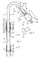
- FIG. 1 shows a device designed as a telescopic standpipe for the conduction of water, which is supported by a submerged entirely in water submersible pump to a lying above the water surface discharge location.
- the submersible pump not shown, has a substantially vertically upward from the submersible pump housing leading cylindrical screw connection piece 1, at its end an external thread 2 is formed.
- the threaded connector 1 is designed to cooperate with a later-described connection device of the line unit and allows a liquid-tight, rigid but detachable attachment of the line unit to the submersible pump.
- the illustrated embodiment of a conduit unit 5 is formed as a rigid telescopic tube with a curvature.
- the telescopic tube has a lower, first tube segment 6 and a parallel to the longitudinal axis of the tube segment slidably disposed upper, second tube segment 7, which has a smaller diameter than the first tube segment.
- Both pipe segments 6, 7 are made of rigid, thin-walled seamless aluminum tubes and are circular in cross-section.
- the lower, first pipe segment 6 has at its end facing the nozzle 1 on a flaring 8 in the form of an outwardly directed collar, which is engaged behind in the axial direction of the tube.
- an inwardly directed chamfer 9 is formed, which will be described in more detail in connection with FIG.
- the upper tube segment 7 is similarly formed at its ends and has a flaring 10 at its lower end inserted into the first tube segment 6 and a chamfer 11 at its other, free end.
- the provided with the chamfer 11 free pipe end forms a liquid discharge 12, which is liquid-conductively connected to the nozzle 1 by the telescopic tube 5.
- the inner diameter of the lower tube segment 6 in the region of the chamfer 9 substantially corresponds to the outer diameter of the upper tube segment 7, while the outer diameter of the upper Pipe segment 7 in the region of the flaring 10 substantially corresponds to the inner diameter of the lower pipe segment.
- the inwardly directed pipe end in the region of the chamfer 9 engages behind the flaring 10 in the axial direction, while in the axial direction it engages behind the diameter constriction in the region of the chamfer 9.
- the inserted into the lower tube segment 6 upper tube segment is captively secured in the lower tube segment 6 and can not be completely pulled out of this up.
- This pipe connection with stop against withdrawal is also almost liquid impermeable because of the matched diameter.
- a connecting device 15 is provided for releasably connecting the line unit 5 with the submersible pump.
- An essential element of the connecting device 15 is a substantially cylindrical plastic sleeve 16. This has a cylindrical upper portion 17 whose inner diameter is slightly larger than the outer diameter of the lower tubular segment 6 and on the outer circumference axially extending grip ribs are formed.
- an inwardly directed collar 18 is formed, whose inner diameter corresponds substantially to the outer diameter of the lower tube segment 6.
- a downwardly adjoining the collar 18 lower portion 19 has an inner diameter which substantially corresponds to the outer diameter of the lower tube segment 6 in the region of the flaring 8.
- the lower portion 19 has an internal thread 20 which is provided for cooperation with the external thread 2 of the nozzle 1.
- the plastic sleeve 16 is screwed manually with the internal thread 20 on the external thread 2 of the connecting piece 1.
- the inwardly directed projection 18 of the sleeve presses the crimped edge of the lower tube segment 6 with the interposition of a plastic gasket 21 against the upper edge of the connecting piece 1 and thereby produces a mechanically strong and sufficiently waterproof liquid-conducting connection between the line unit 5 and submersible pump.
- the holding element 25 has a lower portion 26 with an inner diameter which corresponds substantially to the outer diameter of the lower tube segment 6, but may have a slight undersize. Above a collar-shaped diameter widening 27, an upper section 28 adjoins, the inner diameter of which substantially corresponds to the outer diameter of the second tube segment 7. As a result, the upper portion 28 of the holder 25 acts as a guide for the upper tube segment 7 in axial displacement. On the outside of the upper portion 28, an external thread 29 is formed.
- the upper edge region of the holder 25 is designed to form a seal by the edge inwards, i. to the upper tube segment 7 out, a running approximately 45 ° to the tube axis bevel 30 has.
- the chamfer 9 of the upper tube end shown in detail in FIG. 2 is preferably produced by rolling, wherein at the same time a small, sharp, outwardly directed ridge 31 is formed, which engages positively in the soft plastic material of the holder 25 and the lower tube segment in the Plastic holder 25 firmly anchored against withdrawal.
- a slotted plastic sleeve 35 is slid from the side of the chamfer 11 forth, the cylindrical inner diameter substantially corresponds to the outer diameter of the upper tube segment 7.
- the sleeve 35 has an annularly closed, cylindrical lower portion 36 which faces the holder 25, and an upper portion 37 integrally formed with the lower portion, in which four equally distributed around the circumference of the sleeve 35 from the upper end to the ring portion 36 slightly tapered axial slots are recessed. In the region of the slots, the sleeve 35 is spreadable or compressible by radial movement of the tabs formed between the slots.
- the tabs separated by the slots have conical oblique surfaces 38 on their outer widths which, in the direction of the lower tube segment 6, effect an outer diameter enlargement of the sleeve 35.
- a conical chamfer 39 is attached at the lower front end of the lower portion 36.
- the chamfer 39 bounded together with the chamfer 30 of the holder 25 has a cross-sectionally substantially triangular or trapezoidal annular space which widens towards the upper tube segment 7 and in which a plastic O-ring 40 is inserted.
- the clamping sleeve 45 has an upper portion 46, on the substantially cylindrical outer surface axial gripping grooves are mounted. On the inner circumference of the upper portion 46, a conical inclined surface 47 is formed, which corresponds to the inclined surfaces 38 of the slotted sleeve 35 and bears substantially over the entire surface thereof.
- the down to the inclined surface 47 adjacent cylindrical portion has an inner diameter which substantially corresponds to the outer diameter of the annular lower portion 36 of the slotted sleeve 35, so that the clamping sleeve is guided in this area on the slotted sleeve.
- an outer diameter extended lower portion 48 is formed, which has an internal thread 49 which can be screwed onto the external thread 29 of the holding element 25.
- the clamping sleeve 45 is at least partially unscrewed from the holder 25, so that the inclined surfaces 38, 47 axially against each other, whereby a force acting on the tabs of the slotted sleeve 35 inward radial force is released.
- the upper tube segment 7 can be moved axially relative to the lower tube segment 6, wherein the inwardly bent edge of the chamfer 9 together with the flaring 10 forms an axial stop against complete pulling apart of the tube segments.
- the pipe segments 6, 7 are shifted to one another in the desired relative position. If the desired length of the line unit 5 is set, then the clamping sleeve 45 is screwed onto the holder 25 manually. In the region of the slanting surfaces sliding on each other, the tabs of the slotted sleeve 35 are pressed inwardly on the tube segment 7 and ensure a frictional fixing of the upper tube in its relative position to the lower tube and for an overall rigid connection of the tube segments, so that the line unit. 5 is completely rigid.
- the slotted sleeve 35 is slightly axially displaced towards the lower tube 6, whereby the sealing ring 40 lying between the bevels 30, 39 is clamped between the cooperating bevels and seals the connection point in a liquid-tight manner on all sides.
- a pipe segments liquid-tight sealing sealing device is formed between the two pipe segments.
- the upper tube segment 7 has subsequently to the leading into the lower tube segment 6 straight pipe section 55 a circular arc-shaped bend 56, which leads to a further straight pipe section 57 of the upper pipe segment 7.
- the straight pipe sections 55, 57 on both sides of the bend 56 are at an angle of approximately 145 ° to each other.
- the bend has a radius of curvature which corresponds approximately to three times the diameter of the upper tube segment 7.
- the line unit 5 can be hung at the top of the water tank with the bend in the manner of a hook. Due to the length adjustability of the telescopic tube arrangement, the pump, possibly with the interposition of extension tube sections, are lowered to the container bottom, in which case the sheet does not have to rest directly on the container edge. However, the length of the conduit unit may also be adjusted so that the water inlet of the pump, usually the bottom of the pump, maintains a certain distance from the container bottom, with the arc 56 of the inner tube 7 resting on the container rim and determining the vertical pumping position.
- the whereabouts of a minimum volume of water in a reservoir can be set via such an arrangement of the submersible pump at a certain height above a reservoir bottom.
- the bend 56 of the overall rigid arrangement also forms a comfortable handle in the manner of a walking stick handle, by means of which the rigidly attached to the line unit 5 submersible pump can be parked in places difficult to access in a liquid container or reservoir.
- a plastic holder 60 is attached, whose structure corresponds substantially to the structure of the holding element 25.
- the lower portion 61 is slightly shorter and at the top, provided with a non-visible external thread portion is no chamfer provided.
- the chamfer 11 is also made by rolling and has along its outer periphery a radially projecting ridge, which burrows into the soft plastic material of the holder 60 and this anchored against slipping on the pipe end.
- the plastic holder 60 serves as a connecting element to which, for example, the shut-off device 65 shown in FIG. 1 can be screwed.
- the shut-off device 65 is designed as a continuously adjustable shut-off valve and has a two-armed operating lever 66, over which a rotatable in a valve housing 67 valve body is rotated.
- the intended for manual operation lever 66 expediently away from the vertical in Fig. 1 section of the telescopic tube assembly, which facilitates the operation.
- the taching pump can continue to run continuously without loss of water, even if the liquid withdrawal is interrupted frequently, as in the case of repeated filling of a watering can, for example.
- a nipple 68 Integral with the valve housing 67, a nipple 68 is provided for a hose quick coupling.
- This allows for a direct water extraction with a sufficiently well-bundled beam and on the other hand, the connection of any device, in particular with the interposition of a hose. It thus forms one of the liquid discharge 12 liquid-conducting associated terminal device, which allows the connection of a further liquid line and at the same time forms a liquid discharge opening itself.
- the outflow direction in the end region 12 of the curved tube or of the tubing connecting piece 68 attached thereto is advantageously inclined obliquely downwards when the vertical position of the standpipe is vertical. This allows a comfortable handling of the shut-off valve and the hose connection piece.
- the valve housing 67 may be slidably mounted rotatably on the holder 60 so that misalignments when pressing the holder 60 on the upper tube can still be corrected or that in individual cases for better handling of the actuating lever 66 can be directed to another position.
- a fastening means for tool-free attachment of an electrical supply cable for the submersible pump is provided on the straight portion 57 of the upper tube segment 7, a fastening means for tool-free attachment of an electrical supply cable for the submersible pump is provided.
- the fastening means is designed as a clamp holder for the cable. He has two limited by spreadable fingers, successively arranged openings, the smaller opening 71 is accessible only through the larger opening 72.
- the supply cable is clipped with slight spreading of the fingers surrounding the openings from the side of the larger opening into the smaller opening 71.
- the clamp holder 70 can be clipped with renewed spreading of the fingers on a pipe of the line unit that the tube passes through the larger opening 72, wherein the fingers largely surround the tube laterally.
- a straight standpipe 6 is screwed onto a pump outlet 1 which discharges upwards at the pump housing, in which an inner tube 7 is telescopically displaceable.
- the relative position of the two telescoping tubes can be determined by tightening a cap screw sleeve clamping.
- the end of the inner tube facing away from the standpipe is angled and ends in a shut-off valve 65 with hose connection 68.
- the bend 56 which is preferably designed as a bend of the inner tube 7, allows the attachment of the assembly to the edge of a vessel.
- a line unit according to the invention can also be used advantageously with conventional, can be erected outside a liquid reservoir floor pumps, which suck the liquid via a suction hose from a reservoir.
- a rigid rigid line unit connected to a floor pump forms a convenient operated Füsstechniksent Spotifystelle with a preferably height-adjustable and storable liquid outlet. It can be a portable, installable faucet can be created.
Landscapes
- Engineering & Computer Science (AREA)
- General Engineering & Computer Science (AREA)
- Mechanical Engineering (AREA)
- Structures Of Non-Positive Displacement Pumps (AREA)
Claims (13)
- Dispositif pour la conduction d'un liquide à partir d'une pompe submersible pouvant être immergé au moins en partie dans le liquide à une sortie de liquide pouvant être disposée à l'extérieur du liquide, le dispositif présentant une unité de guidage (5) rigide à la flexion réalisée pour un raccordement rigide et désserrable avec la pompe submersible, l'unité de guidage (5) présentant une longueur variable, caractérisé en ce que l'unité de guidage présente un moyen d'obturation (65) pour le moyen d'évacuation des liquides (12) et/ou un moyen de raccordement (68) associé au moyen d'évacuation des liquides (12) pour le raccordement d'un autre conduit de liquides.
- Dispositif d'après la revendication 1, caractérisé en ce que la longueur de l'unité de guidage peut être variée de manière continue et qu'elle peut être fixée de préférence sans outils.
- Dispositif d'après la revendication 1 ou 2, caractérisé en ce que l'unité de guidage (5) est réalisée en tant que gaine télescopique, de préférence avec un premier segment de tuyau (6) et un deuxième segment de tuyau disposé de manière déplaçable dans le premier segment de tuyau, le premier segment de tuyau (6) et le deuxième segment de tuyau (7) pouvant être fixés l'un à l'autre par un moyen de serrage (25, 35, 45) et/ou qu'entre le premier segment de tuyau (6) et le deuxième segment de tuyau (7) est prévu un moyen antifuite (30, 39, 40) étanchant les segments de tuyau à l'épreuve des liquides.
- Dispositif d'après la revendication 1 ou 2, caractérisé en ce que l'unité de guidage (5) est tellement rigide à la flexion, que la pompe submersible peut être déplacée par des mouvements de l'unité de guidage.
- Dispositif d'après une des revendications précédentes, caractérisé en ce que l'unité de guidage (5) présente un tuyau (6, 7) rigide à la flexion, notamment un tuyau métallique, de préférence en aluminium.
- Dispositif d'après une des revendications précédentes, caractérisé en ce que l'unité de guidage (5), notamment le tuyau, présente une courbure (56), formant de préférence un angle de plus de 90°, l'angle présentant notamment une valeur entre 120° et 160°, de préférence à peu près de 1450.
- Dispositif d'après la revendication 6, caractérisé en ce que la courbure (56) présente un rayon de courbure de préférence uniforme, qui se monte à une valeur entre le double et le quintuple du diamètre du conduit de liquide, de préférence à une valeur correspondant à peu près au triple, et/ou en ce que la courbure (56) est réalisée par une flexion du tuyau (7).
- Dispositif d'après une des revendications de 3 à 7, caractérisé en ce qu'au moins un segment de tuyau, de préférence le premier segment de tuyau (1) est droit et en ce qu'un autre segment de tuyau, de préférence le deuxième segment de tuyau (7) présente la courbure (56) et/ou en ce que le tuyau (7) présente une partie de tuyau (55, 57) droite au moins d'un côté de la courbure (56), de préférence des deux côtés de la courbure.
- Dispositif d'après une des revendications précédentes, caractérisé en ce qu'auprès de l'unité de guidage, notamment auprès du premier segment de tuyau est prévu un moyen de raccordement (15) pour la jonction rigide et capable de conduire des liquides, de l'unité de guidage avec une sortie des liquides de la pompe submersible, le moyen de raccordement (15) étant de préférence réalisé en tant que raccordement à vis pouvant être actionné de préférence manuellement.
- Dispositif d'après une des revendications précédentes, caractérisé en ce que le moyen d'obturation (65) pour le moyen d'évacuation des liquides (12) pouvant être actionné de manière manuelle, le moyen d'obturation étant réalisé de préférence en tant que soupape d'arrêt pouvant notamment être réglé de manière progressive et continue.
- Dispositif d'après une des revendications précédentes, caractérisé en ce que le moyen de raccordement est réalisé en tant que raccord rapide de tuyaux (68).
- Configuration de pompe submersible avec une pompe submersible pouvant être immergée au moins en partie dans le liquide et une unité de guidage (5) rigide à la flexion étant raccordée de manière rigide et désserrable à la sortie de la pompe submersible, l'unité de guidage (5) présentant une longueur variable, caractérisé en ce que l'unité de guidage présente un moyen d'obturation (65) pour le moyen d'évacuation des liquides (12) et/ou un moyen de raccordement (68) associé au moyen d'évacuation des liquides (12) pour le raccordement d'un autre conduit de liquides.
- Configuration de pompe submersible d'après la revendication 12, caractérisé par les caractéristiques de la partie significatives d'après au moins une des revendications de 2 à 11.
Priority Applications (3)
| Application Number | Priority Date | Filing Date | Title |
|---|---|---|---|
| DE29824965U DE29824965U1 (de) | 1997-08-29 | 1998-07-16 | Vorrichtung zur Leitung einer Flüssigkeit |
| DE29825017U DE29825017U1 (de) | 1997-08-29 | 1998-07-16 | Vorrichtung zur Leitung einer Flüssigkeit |
| DE29825118U DE29825118U1 (de) | 1997-08-29 | 1998-07-16 | Vorrichtung zur Leitung einer Flüssigkeit |
Applications Claiming Priority (2)
| Application Number | Priority Date | Filing Date | Title |
|---|---|---|---|
| DE19737670 | 1997-08-29 | ||
| DE19737670A DE19737670B4 (de) | 1997-08-29 | 1997-08-29 | Vorrichtung zur Leitung einer Flüssigkeit |
Publications (3)
| Publication Number | Publication Date |
|---|---|
| EP0899461A1 EP0899461A1 (fr) | 1999-03-03 |
| EP0899461B1 EP0899461B1 (fr) | 2002-01-16 |
| EP0899461B2 true EP0899461B2 (fr) | 2006-08-02 |
Family
ID=7840544
Family Applications (1)
| Application Number | Title | Priority Date | Filing Date |
|---|---|---|---|
| EP98113238A Expired - Lifetime EP0899461B2 (fr) | 1997-08-29 | 1998-07-16 | Pompe immergée avec une conduit de décharge rigide |
Country Status (3)
| Country | Link |
|---|---|
| EP (1) | EP0899461B2 (fr) |
| AT (1) | ATE212108T1 (fr) |
| DE (3) | DE19737670B4 (fr) |
Cited By (3)
| Publication number | Priority date | Publication date | Assignee | Title |
|---|---|---|---|---|
| CN110030448A (zh) * | 2019-05-21 | 2019-07-19 | 上饶市圣麦司科技有限公司 | 一种水龙头伸缩出水管 |
| EP3827664A1 (fr) * | 2019-11-29 | 2021-06-02 | Robert Bosch GmbH | Dispositif d'arrosage |
| US12612916B2 (en) | 2021-06-16 | 2026-04-28 | Techtronic Cordless Gp | Portable pump with telescopic tubes |
Families Citing this family (4)
| Publication number | Priority date | Publication date | Assignee | Title |
|---|---|---|---|---|
| DE102009044087A1 (de) * | 2009-09-23 | 2011-03-24 | Gardena Manufacturing Gmbh | Gartenpumpe, insbesondere Regenfasspumpe |
| DE102009048022A1 (de) * | 2009-10-02 | 2011-04-07 | J. Wagner Gmbh | Transportables Farbsprühgerät |
| EP2867568B1 (fr) * | 2012-06-27 | 2017-05-31 | Husqvarna AB | Ensemble raccord |
| CN222949118U (zh) | 2024-08-13 | 2025-06-06 | 恺霖卫浴科技(厦门)有限公司 | 一种可调节的淋浴管组 |
Family Cites Families (12)
| Publication number | Priority date | Publication date | Assignee | Title |
|---|---|---|---|---|
| FR750085A (fr) * | 1932-04-28 | 1933-08-03 | Tecalemit | Perfectionnements aux pompes à liquides comportant un rotor de forme hélicoïdale, et application aux appareils transvaseurs de liquides |
| US3085513A (en) * | 1961-07-31 | 1963-04-16 | March Mfg Co | Portable immersion electric liquid pump |
| DE2165889C2 (de) * | 1971-12-31 | 1974-01-10 | Bergwerksverband Gmbh, 4300 Essen | Blasvorrichtung zum Hinterfüllen von Streckenausbau |
| AT329109B (de) * | 1973-11-08 | 1976-04-26 | Universale Hoch & Tiefbau | Vorrichtung zum auskleiden von tunneln oder stollen mit pumpbeton |
| US4059922A (en) * | 1976-01-12 | 1977-11-29 | Digiacinto Joseph A | Sprayer hydroponic grower |
| DE3128995A1 (de) * | 1981-07-22 | 1983-02-10 | Rheinhütte vorm. Ludwig Beck & Co, 6200 Wiesbaden | Anlage zum betanken von kraftfahrzeugen mit fluessigen, insbesondere kryogenen treibstoffen |
| DE3339722A1 (de) * | 1983-11-03 | 1985-05-15 | Robert Krups Stiftung & Co KG, 5650 Solingen | Elektrisches fritiergeraet |
| FR2597708B1 (fr) * | 1986-04-24 | 1989-05-05 | Benedetti Michel | Dispositif pour l'arrosage automatique des sols. |
| DE3921549C2 (de) * | 1989-06-30 | 1993-11-18 | Abs Pumpen Ag | Tauchmotorpumpe |
| DE9104697U1 (de) * | 1991-04-17 | 1991-07-18 | Ellwart, Heinrich | Gießkanne |
| US5380158A (en) * | 1993-12-09 | 1995-01-10 | Gerbitz; Daniel R. | Apparatus and method for holding a sump pump |
| US5577895A (en) * | 1995-02-24 | 1996-11-26 | Fe Petro Inc. | Submerged pump unit having a variable length pipe assembly |
-
1997
- 1997-08-29 DE DE19737670A patent/DE19737670B4/de not_active Expired - Fee Related
- 1997-08-29 DE DE19758947A patent/DE19758947B4/de not_active Expired - Fee Related
-
1998
- 1998-07-16 DE DE59802616T patent/DE59802616D1/de not_active Expired - Lifetime
- 1998-07-16 EP EP98113238A patent/EP0899461B2/fr not_active Expired - Lifetime
- 1998-07-16 AT AT98113238T patent/ATE212108T1/de not_active IP Right Cessation
Cited By (3)
| Publication number | Priority date | Publication date | Assignee | Title |
|---|---|---|---|---|
| CN110030448A (zh) * | 2019-05-21 | 2019-07-19 | 上饶市圣麦司科技有限公司 | 一种水龙头伸缩出水管 |
| EP3827664A1 (fr) * | 2019-11-29 | 2021-06-02 | Robert Bosch GmbH | Dispositif d'arrosage |
| US12612916B2 (en) | 2021-06-16 | 2026-04-28 | Techtronic Cordless Gp | Portable pump with telescopic tubes |
Also Published As
| Publication number | Publication date |
|---|---|
| ATE212108T1 (de) | 2002-02-15 |
| EP0899461B1 (fr) | 2002-01-16 |
| EP0899461A1 (fr) | 1999-03-03 |
| DE59802616D1 (de) | 2002-02-21 |
| DE19737670B4 (de) | 2008-07-03 |
| DE19758947B4 (de) | 2010-04-08 |
| DE19737670A1 (de) | 1999-03-04 |
Similar Documents
| Publication | Publication Date | Title |
|---|---|---|
| EP0899461B2 (fr) | Pompe immergée avec une conduit de décharge rigide | |
| EP2501940B1 (fr) | Pompe de jardin avec support de rangement de tubes | |
| DE10158114B4 (de) | Anschlussvorrichtung für Wellschauchleitung und Leitungssystem | |
| DE29825017U1 (de) | Vorrichtung zur Leitung einer Flüssigkeit | |
| EP3006636B1 (fr) | Évacuation murale avec pompe | |
| EP3656936B1 (fr) | Système de levage | |
| DE69817983T2 (de) | Reinigungsvorrichtung | |
| DE202004008849U1 (de) | Pumpenanordnung | |
| DE4328409A1 (de) | Schlauchkupplung | |
| DE10326300A1 (de) | Sanitärschlauch mit drehbarer Kupplung für ein Anschlussstück | |
| EP2569096B1 (fr) | Lance à jet réglable à longeur comprenant une poignée axialement réglable | |
| EP1043537A1 (fr) | Système sous pression, verin et bride de fixation | |
| DE3442179A1 (de) | Abwasserrohrstueck fuer eine verstellbare steckverbindung | |
| CH686496A5 (de) | Reinigungseinrichtung. | |
| DE2609374A1 (de) | Einsteckteil | |
| DE20308477U1 (de) | Reinigungsgerät | |
| WO1991000428A1 (fr) | Pompe a moteur submersible | |
| DE8309754U1 (de) | Ueberlaufsicherung fuer fluessigkeitsbehaelter, insbesondere regentonne | |
| DE3413002A1 (de) | Freiland-zapfstelle fuer wasserleitungen, insbesondere fuer beregnungsanlagen | |
| DE20111177U1 (de) | Kontrollschacht | |
| EP4691954A1 (fr) | Support de tuyau | |
| DE102010017589B3 (de) | Rahmenstandpumpe | |
| AT18336U1 (de) | Anschlussstück für Schläuche | |
| DE3124311A1 (de) | "pumpvorrichtung" | |
| DE20211996U1 (de) | Sicherheitsschlaucheinbindung mit Sicherheitskonus |
Legal Events
| Date | Code | Title | Description |
|---|---|---|---|
| PUAI | Public reference made under article 153(3) epc to a published international application that has entered the european phase |
Free format text: ORIGINAL CODE: 0009012 |
|
| AK | Designated contracting states |
Kind code of ref document: A1 Designated state(s): AT CH DE FR GB IT LI NL SE |
|
| AX | Request for extension of the european patent |
Free format text: AL;LT;LV;MK;RO;SI |
|
| 17P | Request for examination filed |
Effective date: 19990825 |
|
| AKX | Designation fees paid |
Free format text: AT CH DE FR GB IT LI NL SE |
|
| 17Q | First examination report despatched |
Effective date: 20001005 |
|
| GRAG | Despatch of communication of intention to grant |
Free format text: ORIGINAL CODE: EPIDOS AGRA |
|
| GRAG | Despatch of communication of intention to grant |
Free format text: ORIGINAL CODE: EPIDOS AGRA |
|
| GRAH | Despatch of communication of intention to grant a patent |
Free format text: ORIGINAL CODE: EPIDOS IGRA |
|
| GRAH | Despatch of communication of intention to grant a patent |
Free format text: ORIGINAL CODE: EPIDOS IGRA |
|
| GRAA | (expected) grant |
Free format text: ORIGINAL CODE: 0009210 |
|
| REG | Reference to a national code |
Ref country code: GB Ref legal event code: IF02 |
|
| AK | Designated contracting states |
Kind code of ref document: B1 Designated state(s): AT CH DE FR GB IT LI NL SE |
|
| PG25 | Lapsed in a contracting state [announced via postgrant information from national office to epo] |
Ref country code: NL Free format text: LAPSE BECAUSE OF FAILURE TO SUBMIT A TRANSLATION OF THE DESCRIPTION OR TO PAY THE FEE WITHIN THE PRESCRIBED TIME-LIMIT Effective date: 20020116 Ref country code: GB Free format text: LAPSE BECAUSE OF FAILURE TO SUBMIT A TRANSLATION OF THE DESCRIPTION OR TO PAY THE FEE WITHIN THE PRESCRIBED TIME-LIMIT Effective date: 20020116 |
|
| REF | Corresponds to: |
Ref document number: 212108 Country of ref document: AT Date of ref document: 20020215 Kind code of ref document: T |
|
| REG | Reference to a national code |
Ref country code: CH Ref legal event code: EP |
|
| REF | Corresponds to: |
Ref document number: 59802616 Country of ref document: DE Date of ref document: 20020221 |
|
| NLV1 | Nl: lapsed or annulled due to failure to fulfill the requirements of art. 29p and 29m of the patents act | ||
| ET | Fr: translation filed | ||
| PG25 | Lapsed in a contracting state [announced via postgrant information from national office to epo] |
Ref country code: AT Free format text: LAPSE BECAUSE OF NON-PAYMENT OF DUE FEES Effective date: 20020716 |
|
| GBV | Gb: ep patent (uk) treated as always having been void in accordance with gb section 77(7)/1977 [no translation filed] |
Effective date: 20020116 |
|
| PG25 | Lapsed in a contracting state [announced via postgrant information from national office to epo] |
Ref country code: LI Free format text: LAPSE BECAUSE OF NON-PAYMENT OF DUE FEES Effective date: 20020731 Ref country code: CH Free format text: LAPSE BECAUSE OF NON-PAYMENT OF DUE FEES Effective date: 20020731 |
|
| PLBQ | Unpublished change to opponent data |
Free format text: ORIGINAL CODE: EPIDOS OPPO |
|
| PLBI | Opposition filed |
Free format text: ORIGINAL CODE: 0009260 |
|
| PLBF | Reply of patent proprietor to notice(s) of opposition |
Free format text: ORIGINAL CODE: EPIDOS OBSO |
|
| 26 | Opposition filed |
Opponent name: HOFFMANN MASCHINENBAU GMBH Effective date: 20021016 |
|
| REG | Reference to a national code |
Ref country code: CH Ref legal event code: PL |
|
| PLBF | Reply of patent proprietor to notice(s) of opposition |
Free format text: ORIGINAL CODE: EPIDOS OBSO |
|
| PLBF | Reply of patent proprietor to notice(s) of opposition |
Free format text: ORIGINAL CODE: EPIDOS OBSO |
|
| RAP2 | Party data changed (patent owner data changed or rights of a patent transferred) |
Owner name: GARDENA MANUFACTURING GMBH |
|
| APBP | Date of receipt of notice of appeal recorded |
Free format text: ORIGINAL CODE: EPIDOSNNOA2O |
|
| APAH | Appeal reference modified |
Free format text: ORIGINAL CODE: EPIDOSCREFNO |
|
| APAH | Appeal reference modified |
Free format text: ORIGINAL CODE: EPIDOSCREFNO |
|
| APBU | Appeal procedure closed |
Free format text: ORIGINAL CODE: EPIDOSNNOA9O |
|
| PUAH | Patent maintained in amended form |
Free format text: ORIGINAL CODE: 0009272 |
|
| STAA | Information on the status of an ep patent application or granted ep patent |
Free format text: STATUS: PATENT MAINTAINED AS AMENDED |
|
| PGFP | Annual fee paid to national office [announced via postgrant information from national office to epo] |
Ref country code: IT Payment date: 20060731 Year of fee payment: 9 |
|
| 27A | Patent maintained in amended form |
Effective date: 20060802 |
|
| AK | Designated contracting states |
Kind code of ref document: B2 Designated state(s): AT CH DE FR GB IT LI NL SE |
|
| REG | Reference to a national code |
Ref country code: SE Ref legal event code: RPEO |
|
| ET3 | Fr: translation filed ** decision concerning opposition | ||
| PGFP | Annual fee paid to national office [announced via postgrant information from national office to epo] |
Ref country code: SE Payment date: 20060724 Year of fee payment: 9 |
|
| EUG | Se: european patent has lapsed | ||
| PG25 | Lapsed in a contracting state [announced via postgrant information from national office to epo] |
Ref country code: SE Free format text: LAPSE BECAUSE OF NON-PAYMENT OF DUE FEES Effective date: 20070717 |
|
| PG25 | Lapsed in a contracting state [announced via postgrant information from national office to epo] |
Ref country code: IT Free format text: LAPSE BECAUSE OF NON-PAYMENT OF DUE FEES Effective date: 20070716 |
|
| REG | Reference to a national code |
Ref country code: FR Ref legal event code: TP Owner name: HUSQVARNA AB, SE Effective date: 20140407 |
|
| REG | Reference to a national code |
Ref country code: DE Ref legal event code: R081 Ref document number: 59802616 Country of ref document: DE Owner name: HUSQVARNA AB, SE Free format text: FORMER OWNER: GARDENA MANUFACTURING GMBH, 89079 ULM, DE Effective date: 20140627 |
|
| REG | Reference to a national code |
Ref country code: FR Ref legal event code: PLFP Year of fee payment: 19 |
|
| REG | Reference to a national code |
Ref country code: FR Ref legal event code: PLFP Year of fee payment: 20 |
|
| PGFP | Annual fee paid to national office [announced via postgrant information from national office to epo] |
Ref country code: FR Payment date: 20170626 Year of fee payment: 20 |
|
| PGFP | Annual fee paid to national office [announced via postgrant information from national office to epo] |
Ref country code: DE Payment date: 20170529 Year of fee payment: 20 |
|
| REG | Reference to a national code |
Ref country code: DE Ref legal event code: R071 Ref document number: 59802616 Country of ref document: DE |