EP0899461B2 - Submerged pump with a rigid discharge duct - Google Patents
Submerged pump with a rigid discharge duct Download PDFInfo
- Publication number
- EP0899461B2 EP0899461B2 EP98113238A EP98113238A EP0899461B2 EP 0899461 B2 EP0899461 B2 EP 0899461B2 EP 98113238 A EP98113238 A EP 98113238A EP 98113238 A EP98113238 A EP 98113238A EP 0899461 B2 EP0899461 B2 EP 0899461B2
- Authority
- EP
- European Patent Office
- Prior art keywords
- liquid
- pipe
- submersible pump
- duct unit
- pipe segment
- Prior art date
- Legal status (The legal status is an assumption and is not a legal conclusion. Google has not performed a legal analysis and makes no representation as to the accuracy of the status listed.)
- Expired - Lifetime
Links
Images
Classifications
-
- F—MECHANICAL ENGINEERING; LIGHTING; HEATING; WEAPONS; BLASTING
- F04—POSITIVE - DISPLACEMENT MACHINES FOR LIQUIDS; PUMPS FOR LIQUIDS OR ELASTIC FLUIDS
- F04D—NON-POSITIVE-DISPLACEMENT PUMPS
- F04D29/00—Details, component parts, or accessories
- F04D29/40—Casings; Connections of working fluid
- F04D29/406—Casings; Connections of working fluid especially adapted for liquid pumps
-
- F—MECHANICAL ENGINEERING; LIGHTING; HEATING; WEAPONS; BLASTING
- F04—POSITIVE - DISPLACEMENT MACHINES FOR LIQUIDS; PUMPS FOR LIQUIDS OR ELASTIC FLUIDS
- F04D—NON-POSITIVE-DISPLACEMENT PUMPS
- F04D13/00—Pumping installations or systems
- F04D13/02—Units comprising pumps and their driving means
- F04D13/06—Units comprising pumps and their driving means the pump being electrically driven
- F04D13/08—Units comprising pumps and their driving means the pump being electrically driven for submerged use
-
- F—MECHANICAL ENGINEERING; LIGHTING; HEATING; WEAPONS; BLASTING
- F16—ENGINEERING ELEMENTS AND UNITS; GENERAL MEASURES FOR PRODUCING AND MAINTAINING EFFECTIVE FUNCTIONING OF MACHINES OR INSTALLATIONS; THERMAL INSULATION IN GENERAL
- F16L—PIPES; JOINTS OR FITTINGS FOR PIPES; SUPPORTS FOR PIPES, CABLES OR PROTECTIVE TUBING; MEANS FOR THERMAL INSULATION IN GENERAL
- F16L27/00—Adjustable joints, Joints allowing movement
- F16L27/12—Adjustable joints, Joints allowing movement allowing substantial longitudinal adjustment or movement
- F16L27/127—Adjustable joints, Joints allowing movement allowing substantial longitudinal adjustment or movement with means for locking the longitudinal adjustment or movement in the final mounted position
- F16L27/1274—Adjustable joints, Joints allowing movement allowing substantial longitudinal adjustment or movement with means for locking the longitudinal adjustment or movement in the final mounted position by means of a swivel nut
Definitions
- the invention relates to a device for conducting a liquid from a submersible pump immersed at least partially into the liquid to a liquid dispenser which can be arranged outside the liquid, according to the preamble of claim 1 and to a submersible pump arrangement according to the preamble of claim 12
- Submersible pumps are suitable for underwater operation suitable liquid pumps, which are used for example in the context of garden irrigation to promote collected rainwater from wells, ponds or rainwater collection containers. They are also suitable, for example, for pumping out flooded cellars or the like. As a rule, submersible pumps are completely submerged, normally standing on the liquid-coated floor and sucking in the liquid through intake openings near the floor. The liquid is then discharged through a liquid outlet, which is also usually below the liquid surface.
- a hose For directing the conveyed liquid out of the liquid, it is known to connect a hose to a remplisstechniksauslisterstutzen the submersible pump housing, for example via a hose quick coupling.
- the hose is normally mounted before lowering the submersible pump in the liquid at the liquid outlet and forms with its end facing away from the pump a liquid output to which, for example, a syringe, a shower, a sprinkler or irrigation system can be connected.
- a rigid tube can be rigidly and removably attached as a conduit unit.
- An example is shown in US-A-3,085,513.
- the made of iron or copper-de tube is shaped so that its end protrudes beyond the edge of a container into which the submersible pump is inserted.
- a telescopic nozzle tube is provided to produce a fountain fountain. Only the nozzle at the upper end of the nozzle tube protrudes over a water level, while at the lower end of the nozzle tube a branch wrap is envisaged.
- the invention has as its object to provide a device for guiding a pumped by a submersible liquid, which allows a convenient operation and a more efficient use of submersible pump assemblies, especially in the garden area.
- the invention proposes a device with the features of claim 1.
- a rigid pipe unit for guiding the conveyed by the submersible liquid for liquid delivery, which is designed for rigid connection with the submersible pump.
- the detachable connected to the submersible pump, rigid line unit forms after connection to the submersible pump with this submersible Anordnüng that is dimensionally stable and in which the liquid output is in geometrically fixed relationship to the submersible pump.
- the spatial arrangement of the liquid output is therefore determined by the position and position of the usually quite heavy and stable submersible pump. The liquid output therefore requires no additional fixation and must not be held in liquid extraction.
- the line unit has a length which is preferably infinitely variable.
- the submersible pump arrangement can be optimally adapted in its dimensions to the corresponding dimensions of the liquid reservoir and / or the requirements of the spatial arrangement of the liquid dispensing. It is the length of the line unit to the desired level detectable, which in a preferred embodiment without tools, ie without the aid of tools manually is possible.
- the length of the line unit is given essentially by the length of the liquid channel formed by it.
- a preferred embodiment is characterized in that the line unit is constructed as a tube with a plurality of preferably detachably connectable pipe segments. These can be screwed or clamped to one another or to one another, for example, with the interposition of seals.
- the pipe segments may optionally have different lengths, so that the desired length is adjustable via suitable combinations of pipe segments. Straight and / or curved pipe segments can be used. The use of pipe segments has among other manufacturing advantages.
- the line unit is formed as a telescopic tube, whereby a continuous length adjustment is possible at least in a certain length range.
- a first tube segment and an axially displaceably arranged in the first tube segment second tube segment is provided.
- the relative position of the pipe segments to each other can preferably be fixed by a clamping device which defines the pipe segments together and which is preferably manually operable.
- the tube segments can be sealed liquid-tight against each other by means of a sealing device, so that no fluid exits from the liquid channel formed by the line unit between the pump and liquid output even at higher liquid pressures.
- the line unit is self-supporting. Their shape can be substantially stable regardless of the fluid pressure prevailing in the line unit.
- the line unit is so rigid that the submersible pump is movable by movement of the line unit.
- Such a line unit allows handling of the pump assembly in such a way that the submersible pump can be placed using the line unit in the manner of a stem to an otherwise otherwise difficult to access location in the liquid reservoir.
- the line unit has in such an embodiment in addition to the function as a liquid line another function as an extended handle for the submersible pump.
- the conduit unit has at least one, preferably exactly one rigid tube.
- the tube forming a fluid channel expediently provides the necessary rigidity, so that no additional external or internal stiffening elements are necessary.
- the tube may be made of plastic, but in a preferred embodiment is a metallic tube, especially aluminum.
- aluminum is specifically light, so that an inclined installation does not lead to a strong tilt load of the submersible pump arrangement, on the other hand aluminum is corrosion resistant and therefore also suitable for continuous use in potentially aggressive liquids.
- the conduit unit in particular the tube has a bend in which the pumped liquid changes its direction of flow.
- this may possibly be guided around obstacles such as trees, shrubs or the like, while maintaining the flexural rigidity.
- Angling may form an angle of a few degrees or a few tens of degrees.
- the preferably straight line sections adjoining the bend are at an angle of more than 90 ° to one another.
- the angle can be between 120 ° and 160 °, preferably at about 145 °.
- a hook-shaped bend allows, inter alia, the suspension of the entire arrangement, for example, on the upper edge of a water tank with substantially vertical walls.
- the duct means comprises a hooking means for hooking the ducting unit or the pumping assembly formed by ducting unit and pump to a support, e.g. a crossbar or a liquid container wall.
- the bend is kink-free and preferably has a radius of curvature that is between twice and five times the diameter of the liquid line, preferably about three times the diameter of the liquid line. It is preferred if the radius of curvature in the region of the bend is uniform, so that the line, in particular the tube in the region of the bend extends in a circular arc.
- a uniform pipe bend has the advantage in manufacturing that a straight pipe can be used, which can be bent later.
- a not too small, preferably uniform curvature also has fluidic advantages.
- At least one pipe segment preferably the first pipe segment, is straightforward and therefore particularly easy to manufacture.
- Another pipe segment preferably the second pipe segment, has the angling.
- the pipe preferably has a straight pipe section on at least one side of the bend, preferably on both sides of the bend.
- Such an angled pipe or pipe segment is particularly easy to axially adjacent pipe segments and / or other functional units such as pipe connectors or valve devices on the straight pipe sections, connected.
- a connection device for rigid, liquid-conducting connection of the line unit with a liquid outlet of the submersible pump may be provided on the line unit, in particular on the first pipe segment, a connection device for rigid, liquid-conducting connection of the line unit with a liquid outlet of the submersible pump.
- the liquid outlet may be formed, for example, in the form of a vertical standing at just standing submersible nozzle.
- the line unit is detachably connected to the submersible pump, in particular to the liquid outlet of the submersible pump.
- the pump outlet with a common tap piece of a quick coupling to which then a hose can be connected directly.
- a manually operable screw connection is provided.
- the conduit device itself and the submersible pump must not be rotated relative to each other.
- the tube of the line unit is rather frontally mounted on an end face approximately the same diameter of the liquid outlet and connected by means of a connecting device in the manner of a union nut by screwing rigidly with the sosstechniksauslisterstutzen.
- shut-off device for the liquid dispensing, which is preferably designed as a shut-off valve that is in particular continuously adjustable, preferably by hand.
- connection device for connecting a further liquid line to the line unit.
- the further liquid line may in particular be a hose, for example, to a sprinkler o.
- the connection device is designed as a hose quick coupling, to which the hose can be connected quickly and without the aid of tools or from which it can be removed.
- the connecting device may be an integrally formed with a housing of the shut-off nozzle.
- the liquid dispensing is oriented so that when the pump is substantially vertical, the liquid is discharged obliquely downwards. This allows a comfortable handling of the shut-off device and the connecting device.
- An electrical supply cable for the submersible pump can be guided by the line unit associated fastening means, in particular by attachable to this clamp holder, along the dimensionally stable line unit to the submersible pump.
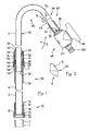
- FIG. 1 shows a device designed as a telescopic standpipe for the conduction of water, which is supported by a submerged entirely in water submersible pump to a lying above the water surface discharge location.
- the submersible pump not shown, has a substantially vertically upward from the submersible pump housing leading cylindrical screw connection piece 1, at its end an external thread 2 is formed.
- the threaded connector 1 is designed to cooperate with a later-described connection device of the line unit and allows a liquid-tight, rigid but detachable attachment of the line unit to the submersible pump.
- the illustrated embodiment of a conduit unit 5 is formed as a rigid telescopic tube with a curvature.
- the telescopic tube has a lower, first tube segment 6 and a parallel to the longitudinal axis of the tube segment slidably disposed upper, second tube segment 7, which has a smaller diameter than the first tube segment.
- Both pipe segments 6, 7 are made of rigid, thin-walled seamless aluminum tubes and are circular in cross-section.
- the lower, first pipe segment 6 has at its end facing the nozzle 1 on a flaring 8 in the form of an outwardly directed collar, which is engaged behind in the axial direction of the tube.
- an inwardly directed chamfer 9 is formed, which will be described in more detail in connection with FIG.
- the upper tube segment 7 is similarly formed at its ends and has a flaring 10 at its lower end inserted into the first tube segment 6 and a chamfer 11 at its other, free end.
- the provided with the chamfer 11 free pipe end forms a liquid discharge 12, which is liquid-conductively connected to the nozzle 1 by the telescopic tube 5.
- the inner diameter of the lower tube segment 6 in the region of the chamfer 9 substantially corresponds to the outer diameter of the upper tube segment 7, while the outer diameter of the upper Pipe segment 7 in the region of the flaring 10 substantially corresponds to the inner diameter of the lower pipe segment.
- the inwardly directed pipe end in the region of the chamfer 9 engages behind the flaring 10 in the axial direction, while in the axial direction it engages behind the diameter constriction in the region of the chamfer 9.
- the inserted into the lower tube segment 6 upper tube segment is captively secured in the lower tube segment 6 and can not be completely pulled out of this up.
- This pipe connection with stop against withdrawal is also almost liquid impermeable because of the matched diameter.
- a connecting device 15 is provided for releasably connecting the line unit 5 with the submersible pump.
- An essential element of the connecting device 15 is a substantially cylindrical plastic sleeve 16. This has a cylindrical upper portion 17 whose inner diameter is slightly larger than the outer diameter of the lower tubular segment 6 and on the outer circumference axially extending grip ribs are formed.
- an inwardly directed collar 18 is formed, whose inner diameter corresponds substantially to the outer diameter of the lower tube segment 6.
- a downwardly adjoining the collar 18 lower portion 19 has an inner diameter which substantially corresponds to the outer diameter of the lower tube segment 6 in the region of the flaring 8.
- the lower portion 19 has an internal thread 20 which is provided for cooperation with the external thread 2 of the nozzle 1.
- the plastic sleeve 16 is screwed manually with the internal thread 20 on the external thread 2 of the connecting piece 1.
- the inwardly directed projection 18 of the sleeve presses the crimped edge of the lower tube segment 6 with the interposition of a plastic gasket 21 against the upper edge of the connecting piece 1 and thereby produces a mechanically strong and sufficiently waterproof liquid-conducting connection between the line unit 5 and submersible pump.
- the holding element 25 has a lower portion 26 with an inner diameter which corresponds substantially to the outer diameter of the lower tube segment 6, but may have a slight undersize. Above a collar-shaped diameter widening 27, an upper section 28 adjoins, the inner diameter of which substantially corresponds to the outer diameter of the second tube segment 7. As a result, the upper portion 28 of the holder 25 acts as a guide for the upper tube segment 7 in axial displacement. On the outside of the upper portion 28, an external thread 29 is formed.
- the upper edge region of the holder 25 is designed to form a seal by the edge inwards, i. to the upper tube segment 7 out, a running approximately 45 ° to the tube axis bevel 30 has.
- the chamfer 9 of the upper tube end shown in detail in FIG. 2 is preferably produced by rolling, wherein at the same time a small, sharp, outwardly directed ridge 31 is formed, which engages positively in the soft plastic material of the holder 25 and the lower tube segment in the Plastic holder 25 firmly anchored against withdrawal.
- a slotted plastic sleeve 35 is slid from the side of the chamfer 11 forth, the cylindrical inner diameter substantially corresponds to the outer diameter of the upper tube segment 7.
- the sleeve 35 has an annularly closed, cylindrical lower portion 36 which faces the holder 25, and an upper portion 37 integrally formed with the lower portion, in which four equally distributed around the circumference of the sleeve 35 from the upper end to the ring portion 36 slightly tapered axial slots are recessed. In the region of the slots, the sleeve 35 is spreadable or compressible by radial movement of the tabs formed between the slots.
- the tabs separated by the slots have conical oblique surfaces 38 on their outer widths which, in the direction of the lower tube segment 6, effect an outer diameter enlargement of the sleeve 35.
- a conical chamfer 39 is attached at the lower front end of the lower portion 36.
- the chamfer 39 bounded together with the chamfer 30 of the holder 25 has a cross-sectionally substantially triangular or trapezoidal annular space which widens towards the upper tube segment 7 and in which a plastic O-ring 40 is inserted.
- the clamping sleeve 45 has an upper portion 46, on the substantially cylindrical outer surface axial gripping grooves are mounted. On the inner circumference of the upper portion 46, a conical inclined surface 47 is formed, which corresponds to the inclined surfaces 38 of the slotted sleeve 35 and bears substantially over the entire surface thereof.
- the down to the inclined surface 47 adjacent cylindrical portion has an inner diameter which substantially corresponds to the outer diameter of the annular lower portion 36 of the slotted sleeve 35, so that the clamping sleeve is guided in this area on the slotted sleeve.
- an outer diameter extended lower portion 48 is formed, which has an internal thread 49 which can be screwed onto the external thread 29 of the holding element 25.
- the clamping sleeve 45 is at least partially unscrewed from the holder 25, so that the inclined surfaces 38, 47 axially against each other, whereby a force acting on the tabs of the slotted sleeve 35 inward radial force is released.
- the upper tube segment 7 can be moved axially relative to the lower tube segment 6, wherein the inwardly bent edge of the chamfer 9 together with the flaring 10 forms an axial stop against complete pulling apart of the tube segments.
- the pipe segments 6, 7 are shifted to one another in the desired relative position. If the desired length of the line unit 5 is set, then the clamping sleeve 45 is screwed onto the holder 25 manually. In the region of the slanting surfaces sliding on each other, the tabs of the slotted sleeve 35 are pressed inwardly on the tube segment 7 and ensure a frictional fixing of the upper tube in its relative position to the lower tube and for an overall rigid connection of the tube segments, so that the line unit. 5 is completely rigid.
- the slotted sleeve 35 is slightly axially displaced towards the lower tube 6, whereby the sealing ring 40 lying between the bevels 30, 39 is clamped between the cooperating bevels and seals the connection point in a liquid-tight manner on all sides.
- a pipe segments liquid-tight sealing sealing device is formed between the two pipe segments.
- the upper tube segment 7 has subsequently to the leading into the lower tube segment 6 straight pipe section 55 a circular arc-shaped bend 56, which leads to a further straight pipe section 57 of the upper pipe segment 7.
- the straight pipe sections 55, 57 on both sides of the bend 56 are at an angle of approximately 145 ° to each other.
- the bend has a radius of curvature which corresponds approximately to three times the diameter of the upper tube segment 7.
- the line unit 5 can be hung at the top of the water tank with the bend in the manner of a hook. Due to the length adjustability of the telescopic tube arrangement, the pump, possibly with the interposition of extension tube sections, are lowered to the container bottom, in which case the sheet does not have to rest directly on the container edge. However, the length of the conduit unit may also be adjusted so that the water inlet of the pump, usually the bottom of the pump, maintains a certain distance from the container bottom, with the arc 56 of the inner tube 7 resting on the container rim and determining the vertical pumping position.
- the whereabouts of a minimum volume of water in a reservoir can be set via such an arrangement of the submersible pump at a certain height above a reservoir bottom.
- the bend 56 of the overall rigid arrangement also forms a comfortable handle in the manner of a walking stick handle, by means of which the rigidly attached to the line unit 5 submersible pump can be parked in places difficult to access in a liquid container or reservoir.
- a plastic holder 60 is attached, whose structure corresponds substantially to the structure of the holding element 25.
- the lower portion 61 is slightly shorter and at the top, provided with a non-visible external thread portion is no chamfer provided.
- the chamfer 11 is also made by rolling and has along its outer periphery a radially projecting ridge, which burrows into the soft plastic material of the holder 60 and this anchored against slipping on the pipe end.
- the plastic holder 60 serves as a connecting element to which, for example, the shut-off device 65 shown in FIG. 1 can be screwed.
- the shut-off device 65 is designed as a continuously adjustable shut-off valve and has a two-armed operating lever 66, over which a rotatable in a valve housing 67 valve body is rotated.
- the intended for manual operation lever 66 expediently away from the vertical in Fig. 1 section of the telescopic tube assembly, which facilitates the operation.
- the taching pump can continue to run continuously without loss of water, even if the liquid withdrawal is interrupted frequently, as in the case of repeated filling of a watering can, for example.
- a nipple 68 Integral with the valve housing 67, a nipple 68 is provided for a hose quick coupling.
- This allows for a direct water extraction with a sufficiently well-bundled beam and on the other hand, the connection of any device, in particular with the interposition of a hose. It thus forms one of the liquid discharge 12 liquid-conducting associated terminal device, which allows the connection of a further liquid line and at the same time forms a liquid discharge opening itself.
- the outflow direction in the end region 12 of the curved tube or of the tubing connecting piece 68 attached thereto is advantageously inclined obliquely downwards when the vertical position of the standpipe is vertical. This allows a comfortable handling of the shut-off valve and the hose connection piece.
- the valve housing 67 may be slidably mounted rotatably on the holder 60 so that misalignments when pressing the holder 60 on the upper tube can still be corrected or that in individual cases for better handling of the actuating lever 66 can be directed to another position.
- a fastening means for tool-free attachment of an electrical supply cable for the submersible pump is provided on the straight portion 57 of the upper tube segment 7, a fastening means for tool-free attachment of an electrical supply cable for the submersible pump is provided.
- the fastening means is designed as a clamp holder for the cable. He has two limited by spreadable fingers, successively arranged openings, the smaller opening 71 is accessible only through the larger opening 72.
- the supply cable is clipped with slight spreading of the fingers surrounding the openings from the side of the larger opening into the smaller opening 71.
- the clamp holder 70 can be clipped with renewed spreading of the fingers on a pipe of the line unit that the tube passes through the larger opening 72, wherein the fingers largely surround the tube laterally.
- a straight standpipe 6 is screwed onto a pump outlet 1 which discharges upwards at the pump housing, in which an inner tube 7 is telescopically displaceable.
- the relative position of the two telescoping tubes can be determined by tightening a cap screw sleeve clamping.
- the end of the inner tube facing away from the standpipe is angled and ends in a shut-off valve 65 with hose connection 68.
- the bend 56 which is preferably designed as a bend of the inner tube 7, allows the attachment of the assembly to the edge of a vessel.
- a line unit according to the invention can also be used advantageously with conventional, can be erected outside a liquid reservoir floor pumps, which suck the liquid via a suction hose from a reservoir.
- a rigid rigid line unit connected to a floor pump forms a convenient operated Füsstechniksent Spotifystelle with a preferably height-adjustable and storable liquid outlet. It can be a portable, installable faucet can be created.
Abstract
Description
Die Erfindung betrifft eine Vorrichtung zur Leitung einer Flüssigkeit von einer mindestens teilweise in die Flüssigkeit eintauchbaren Tauchpumpe zu einer außerhalb der Flüssigkeit anordenbaren Flüssigkeitsausgabe, gemäß dem Oberbegriff von Anspruch 1 sowie eine Tauchpumpenanordnung gemäß dem Oberbegriff von Anspruch 12The invention relates to a device for conducting a liquid from a submersible pump immersed at least partially into the liquid to a liquid dispenser which can be arranged outside the liquid, according to the preamble of
Tauchpumpen sind für den Unterwasserbetrieb geeignete Flüssigkeitspumpen, die beispielsweise im Rahmen der Gartenbewässerung eingesetzt werden, um gesammeltes Regenwasser aus Brunnen, Teichen oder Regenwasser-Sammelbehältem zu fördern. Sie sind beispielsweise auch zum Auspumpen von überfluteten Kellerräumen o. dgl. geeignet. In der Regel befinden sich Tauchpumpen vollständig unter Wasser, wobei sie normalerweise auf dem flüssigkeitsbedeckten Boden stehen und die Flüssigkeit durch bodennahe Ansaugöffnungen ansaugen. Die Flüssigkeit wird dann durch einen Flüssigkeitsauslaß abgegeben, der in der Regel ebenfalls unterhalb der Flüssigkeitsoberfläche liegt.Submersible pumps are suitable for underwater operation suitable liquid pumps, which are used for example in the context of garden irrigation to promote collected rainwater from wells, ponds or rainwater collection containers. They are also suitable, for example, for pumping out flooded cellars or the like. As a rule, submersible pumps are completely submerged, normally standing on the liquid-coated floor and sucking in the liquid through intake openings near the floor. The liquid is then discharged through a liquid outlet, which is also usually below the liquid surface.
Zur Leitung der geförderten Flüssigkeit aus der Flüssigkeit heraus ist es bekannt, einen Schlauch an einen Flüssigkeitsauslaßstutzen des Tauchpumpengehäuses anzuschließen, beispielsweise über eine Schlauch-Schnellkupplung. Der Schlauch wird normalerweise vor Absenken der Tauchpumpe in die Flüssigkeit am Flüssigkeitsauslaß angebracht und bildet mit seinem der Pumpe abgewandten Ende eine Flüssigkeitsausgabe, an die beispielsweise eine Spritze, eine Brause, ein Regner oder eine Bewässerungsanlage angeschlossen werden kann.For directing the conveyed liquid out of the liquid, it is known to connect a hose to a Flüssigkeitsauslaßstutzen the submersible pump housing, for example via a hose quick coupling. The hose is normally mounted before lowering the submersible pump in the liquid at the liquid outlet and forms with its end facing away from the pump a liquid output to which, for example, a syringe, a shower, a sprinkler or irrigation system can be connected.
Bei bekannten Tauchpumpen-Anordnungen mit Tauchpumpe und Schlauch können sich Probleme ergeben, wenn die zur Wasserentnahme am besten geeignete Stelle des Flüssigkeitsreservoirs von außen schwer zugänglich ist. Für die optimale Plazierung der mit einem Handgriff versehenen Tauchpumpe muß sich der Anwender unter Umständen selbst mit Armen oder Füßen in die zu pumpende Flüssigkeit begeben, um die Tauchpumpe optimal aufzustellen. Dies kann insbesondere bei verschmutztem Wasser oder kühler Witterung unangenehm sein. Auch die Wasserentnahme am freien Ende des Schlauches kann umständlich sein, wenn beispielsweise die Flüssigkeitsausgabe nach Art eines Wasserhahns zur Füllung eines Eimers o. dgl. verwendet werden soll. Das freie Schlauchende mit der Flüssigkeitsausgabe muß ggf. mit einer Hand gehalten werden, während die andere Hand den Eimerhält. Das Fehlen einer dritten Hand zum Abstellen der Flüssigkeitszufuhr nach Füllen des Eimers ist in derartigen Situationen schon beklagt worden.In known submersible pump assemblies with submersible pump and hose problems may arise when the most suitable for water extraction point of the liquid reservoir is difficult to access from the outside. For the optimal placement of the submersible pump provided with a handle, the user may even have to go with arms or feet in the liquid to be pumped to optimally set up the submersible pump. This can be unpleasant, especially in dirty water or cold weather. The removal of water at the free end of the hose can be cumbersome, if, for example, the liquid dispensing in the manner of a faucet to fill a bucket o. The like. Should be used. If necessary, the free end of the hose with the liquid dispenser must be held with one hand while the other hand holds the bucket. The lack of a third hand to stop the supply of fluid after filling the bucket has already been complained of in such situations.
Es sind auch Tauchpumpen-Anordnungen bekannt, bei denen am Auslaß der Tauchpumpe ein biegesteifes Rohr als Leitungseinheit starr und lösbar angebracht werden kann. Ein Beispiel ist in der US-A-3 085 513 gezeigt. Das aus Eisen oder Kupfer bestehen-de Rohr ist so geformt, daß sein Ende über den Rand eines Behälters hinausragt, in den die Tauchpumpe eingesetzt ist.There are also submersible pump arrangements are known in which at the outlet of the submersible pump, a rigid tube can be rigidly and removably attached as a conduit unit. An example is shown in US-A-3,085,513. The made of iron or copper-de tube is shaped so that its end protrudes beyond the edge of a container into which the submersible pump is inserted.
Ein anderes Beispiel ist in der DE 39 21 549 gezeigt. Eine für den festen Einbau in einen Schmutzwasser- oder Fäkalienbehälter vorgesehene Tauchpumpe hat einen nach oben gerichteten Auslaß, an den ein U-förmig gebogenes, als Leitungseinheit dienendes Rohrstück angeschraubt werden kann. Das als Flüssigkeitsausgabe dienende freie Ende des Rohrstückes ist nach unten gerichtet. An der Behälterwand des Fäkalienbehälters ragt das freie Ende einer Förderrohrleitung mit einer nach oben offenen Anschlußöffnung in den Behälter. Bei Absenken der mit der U-Rohrleitung verbundenen Tauchpumpe an einem vorgegebenen Platz in den Behälter soll das Ende der Rohrleitung mittels einer Steckkupplung selbstdichtend in die Anschlußöffnung eingleiten. Dies setzt eine genau festgelegte Geometrie des U-Rohrstückes voraus. Bei bekannten Springbrunnenpumpen der Marke "Fontanette" aus dem Prospekt "easytec (196) 100.0/0496 (B) " ist ein teleskopierbares Düsenrohr vorgesehen, um eine Springbrunnenfontäne zu erzeugen. Nur die Düse am oberen Ende des Düsenrohres ragt über einen Wasserspiegel, während am unteren Ende des Düsenrohres ein Zweigumschluß vergesehen ist.Another example is shown in
Die Erfindung stellt sich die Aufgabe, eine Vorrichtung zur Leitung einer von einer Tauchpumpe gepumpten Flüssigkeit zu schaffen, die eine bequeme Bedienung und einen effizienteren Einsatz von Tauchpumpen-Anordnungen insbesondere im Gartenbereich ermöglicht.The invention has as its object to provide a device for guiding a pumped by a submersible liquid, which allows a convenient operation and a more efficient use of submersible pump assemblies, especially in the garden area.
Zur Lösung dieser Aufgabe schlägt die Erfindung eine Vorrichtung mit den Merkmalen von Anspruch 1 vor.To solve this problem, the invention proposes a device with the features of
Gemäß der Erfindung ist zur Leitung der von der Tauchpumpe geförderten Flüssigkeit zur Flüssigkeitsausgabe eine biegesteife Leitungseinheit vorgesehen, die zur starren Verbindung mit der Tauchpumpe ausgebildet ist. Die lösbar an die Tauchpumpe anschließbare, biegesteife Leitungseinheit bildet nach Anschluß an die Tauchpumpe mit dieser eine Tauchpumpen-Anordnüng, die insgesamtformstabil ist und bei der die Flüssigkeitsausgabe in geometrisch fester Beziehung zur Tauchpumpe steht. Die räumliche Anordnung der Flüssigkeitsausgabe ist daher durch die Position und Stellung der in der Regel recht schweren und standsicheren Tauchpumpe festgelegt. Die Flüssigkeitsausgabe benötigt daher keine zusätzliche Fixierung und muß bei Flüssigkeitsentnahme nicht festgehalten werden.According to the invention, a rigid pipe unit is provided for guiding the conveyed by the submersible liquid for liquid delivery, which is designed for rigid connection with the submersible pump. The detachable connected to the submersible pump, rigid line unit forms after connection to the submersible pump with this submersible Anordnüng that is dimensionally stable and in which the liquid output is in geometrically fixed relationship to the submersible pump. The spatial arrangement of the liquid output is therefore determined by the position and position of the usually quite heavy and stable submersible pump. The liquid output therefore requires no additional fixation and must not be held in liquid extraction.
Für einen variablen Einsatz der Tauchpumpen-Anordnung insbesondere in unterschiedlich tiefen und/oder ausgedehnten Flüssigkeitsreservoirs ist erfindungsgemäß vorgesehen, daß die Leitungseinheit eine Länge hat, die, vorzugsweise stufenlos, veränderbar ist. Dadurch kann die Tauchpumpen-Anordnung in ihren Dimensionen den entsprechenden Dimensionen des Flüssigkeitsreservoirs und/oder den Anforderungen an die räumliche Anordnung der Flüssigkeitsausgabe optimal angepaßt werden. Es ist die Länge der Leitungseinheit auf das gewünschte Maß feststellbar, was bei einer bevorzugten Ausführungsform werkzeuglos, d.h. ohne Zuhilfenahme von Werkzeugen manuell möglich ist. Die Länge der Leitungseinheit ist im wesentlichen durch die Länge des durch sie gebildeten Flüssigkeitskanals gegeben.For a variable use of the submersible pump arrangement, in particular in different depths and / or extended liquid reservoirs, it is provided according to the invention that the line unit has a length which is preferably infinitely variable. As a result, the submersible pump arrangement can be optimally adapted in its dimensions to the corresponding dimensions of the liquid reservoir and / or the requirements of the spatial arrangement of the liquid dispensing. It is the length of the line unit to the desired level detectable, which in a preferred embodiment without tools, ie without the aid of tools manually is possible. The length of the line unit is given essentially by the length of the liquid channel formed by it.
Eine bevorzugte Ausführungsform zeichnet sich dadurch aus, daß die Leitungseinheit als Rohr mit mehreren vorzugsweise lösbar miteinander verbindbaren Rohrsegmenten aufgebaut ist. Diese können beispielsweise aneinander oder ineinander geschraubt oder geklemmt werden., ggf. unter Zwischenlage von Dichtungen. Die Rohrsegmente können ggf. unterschiedliche Längen aufweisen, so daß über geeignete Kombinationen von Rohrsegmenten die gewünschte Länge einstellbar ist. Es können gerade und/oder gekrümmte Rohrsegmente verwendet werden. Die Verwendung von Rohrsegmenten hat unter anderem herstellungstechnische Vorteile.A preferred embodiment is characterized in that the line unit is constructed as a tube with a plurality of preferably detachably connectable pipe segments. These can be screwed or clamped to one another or to one another, for example, with the interposition of seals. The pipe segments may optionally have different lengths, so that the desired length is adjustable via suitable combinations of pipe segments. Straight and / or curved pipe segments can be used. The use of pipe segments has among other manufacturing advantages.
Bei einer bevorzugten Ausführungsform ist die Leitungseinheit als Teleskoprohr ausgebildet, wodurch eine stufenlose Längeneinstellung zumindest in einem gewissen Längenbereich möglich ist. Vorzugsweise ist ein erstes Rohrsegment und ein in dem ersten Rohrsegment axial verschiebbar angeordnetes zweites Rohrsegment vorgesehen. Die relative Lage der Rohrsegmente zueinander kann vorzugsweise durch eine Klemmeinrichtung festgesetzt werden, die die Rohrsegmente aneinander festlegt und die vorzugsweise manuell betätigbar ist. Die Rohrsegmente können mittels einer Dichteinrichtung flüssigkeitsdicht gegeneinander abgedichtet sein, so daß zwischen Pumpe und Flüssigkeitsausgabe auch bei höheren Flüssigkeitsdrücken keine Flüssigkeit aus dem durch die Leitungseinheit gebildeten Flüssigkeitskanal austritt.In a preferred embodiment, the line unit is formed as a telescopic tube, whereby a continuous length adjustment is possible at least in a certain length range. Preferably, a first tube segment and an axially displaceably arranged in the first tube segment second tube segment is provided. The relative position of the pipe segments to each other can preferably be fixed by a clamping device which defines the pipe segments together and which is preferably manually operable. The tube segments can be sealed liquid-tight against each other by means of a sealing device, so that no fluid exits from the liquid channel formed by the line unit between the pump and liquid output even at higher liquid pressures.
Für viele Anwendungen kann es ausreichen, wenn die Leitungseinheit selbsttragend ist. Ihre Form kann unabhängig vom in der Leitungseinheit herrschenden Flüssigkeitsdruck im wesentlichen stabil sein. Vorzugsweise ist die Leitungseinheit derart biegesteif, daß die Tauchpumpe durch Bewegung der Leitungseinheit bewegbar ist. Eine derartige Leitungseinheit ermöglicht eine Handhabung der Pumpen-Anordnung in der Art, daß die Tauchpumpe unter Verwendung der Leitungseinheit nach Art eines Stiels an eine ggf. sonst nur schwer zugängliche Stelle im Flüssigkeitsreservoir plaziert werden kann. Die Leitungseinheit hat bei einer derartigen Ausführungsform neben der Funktion als Flüssigkeitsleitung eine weitere Funktion als verlängerter Griff für die Tauchpumpe.For many applications, it may be sufficient if the line unit is self-supporting. Their shape can be substantially stable regardless of the fluid pressure prevailing in the line unit. Preferably, the line unit is so rigid that the submersible pump is movable by movement of the line unit. Such a line unit allows handling of the pump assembly in such a way that the submersible pump can be placed using the line unit in the manner of a stem to an otherwise otherwise difficult to access location in the liquid reservoir. The line unit has in such an embodiment in addition to the function as a liquid line another function as an extended handle for the submersible pump.
Es ist möglich, zur Bildung der Leitungseinheit einen an sich biegeschlaffen Schlauch zu verwenden und durch geeignete Versteifungsmaßnahmen biegesteif zu machen, beispielsweise ihn durch ein im wesentlichen biegesteifes Gestell zu unterstützen. Bei einer bevorzugten Ausführungsform weist die Leitungseinheit mindestens ein, vorzugsweise genau ein biegesteifes Rohr auf. Das einen Flüssigkeitskanal bildende Rohr bringt zweckmäßigerweise die notwendige Steifigkeit mit, so daß keine zusätzlichen äußeren oder inneren Versteifungselemente notwendig sind. Das Rohr kann aus Kunststoff bestehen, ist jedoch bei einer bevorzugten Ausführungsform ein metallisches Rohr, insbesondere aus Aluminium. Aluminium ist einerseits spezifisch leicht, so daß eine Schrägaufstellung nicht zu einer starken Kippbelastung der Tauchpumpen-Anordnung führt, andererseits ist Aluminium korrosionsbeständig und daher auch für den Dauereinsatz in ggf. aggressiven Flüssigkeiten geeignet.It is possible to use a per se flexible hose to form the line unit and to make rigid by suitable stiffening measures, for example, to support him by a substantially rigid frame. In a preferred embodiment, the conduit unit has at least one, preferably exactly one rigid tube. The tube forming a fluid channel expediently provides the necessary rigidity, so that no additional external or internal stiffening elements are necessary. The tube may be made of plastic, but in a preferred embodiment is a metallic tube, especially aluminum. On the one hand aluminum is specifically light, so that an inclined installation does not lead to a strong tilt load of the submersible pump arrangement, on the other hand aluminum is corrosion resistant and therefore also suitable for continuous use in potentially aggressive liquids.
Bei einer bevorzugten Ausführungsform weist die Leitungseinheit, insbesondere das Rohr eine Abwinkelung auf, in der die gepumpte Flüssigkeit ihre Flußrichtung ändert. Durch eine oder mehrere Abwinkelungen im Verlauf der Leitungseinheit kann dieser unter Beibehaltung der Biegesteifigkeit ggf. um Hindernisse wie Bäume, Büsche o. dgl. herumgeführt werden. Eine Abwinkelung kann einen Winkel von wenigen Graden oder wenigen zehn Graden bilden. Bei einer bevorzugten Ausführungsform stehen die an die Abwinkelung anschließenden vorzugsweise geraden Leitungsabschnitte in einem Winkel von mehr als 90° zueinander. Insbesondere kann der Winkel zwischen 120° und 160° liegen, vorzugsweise bei ca. 145°. Eine hakenförmige Abwinkelung erlaubt unter anderem die Einhängung der gesamten Anordnung beispielsweise an der Oberkante eines Wasserbehälters mit im wesentlichen senkrechen Wänden. Durch die Abwinkelung weist die Leitungseinrichtung eine Einhängvorrichtung zum Einhängen der Leitungseinheit oder der aus Leitungseinheit und Pumpe gebildeten Pumpen-Anordnung an eine Halterung wie z.B. einer Querstange oder einer Flüssigkeitsbehälterwand auf.In a preferred embodiment, the conduit unit, in particular the tube has a bend in which the pumped liquid changes its direction of flow. By one or more bends in the course of the line unit, this may possibly be guided around obstacles such as trees, shrubs or the like, while maintaining the flexural rigidity. Angling may form an angle of a few degrees or a few tens of degrees. In a preferred embodiment, the preferably straight line sections adjoining the bend are at an angle of more than 90 ° to one another. In particular, the angle can be between 120 ° and 160 °, preferably at about 145 °. A hook-shaped bend allows, inter alia, the suspension of the entire arrangement, for example, on the upper edge of a water tank with substantially vertical walls. By bending, the duct means comprises a hooking means for hooking the ducting unit or the pumping assembly formed by ducting unit and pump to a support, e.g. a crossbar or a liquid container wall.
Zwar ist eine relativ scharfe Abwinkelung möglich, es ist jedoch bevorzugt, wenn die Abwinkelung knickfrei ist und vorzugsweise einen Krümmungsradius hat, der zwischen dem Doppelten und dem Fünffachen des Durchmessers der Flüssigkeitsleitung beträgt, vorzugsweise ca. das Dreifache des Durchmessers der Flüssigkeitsleitung. Bevorzugt ist es, wenn der Krümmungsradius im Bereich der Abwinkelung gleichmäßig ist, so daß die Leitung, insbesondere das Rohr im Bereich der Abwinkelung kreisbogenförmig verläuft. Eine gleichmäßige Rohrkrümmung hat in der Fertigung den Vorteil, daß ein gerades Rohr eingesetzt werden kann, welches nachträglich gebogen werden kann. Eine nicht zu kleine, vorzugsweise gleichmäßige Krümmung hat zudem strömungstechnische Vorteile.Although a relatively sharp bend is possible, it is preferred if the bend is kink-free and preferably has a radius of curvature that is between twice and five times the diameter of the liquid line, preferably about three times the diameter of the liquid line. It is preferred if the radius of curvature in the region of the bend is uniform, so that the line, in particular the tube in the region of the bend extends in a circular arc. A uniform pipe bend has the advantage in manufacturing that a straight pipe can be used, which can be bent later. A not too small, preferably uniform curvature also has fluidic advantages.
Bei einer bevorzugten Ausführungsform ist mindestens ein Rohrsegment, vorzugsweise das erste Rohrsegment gerade und damitfertigungstechnisch besonders einfach herzustellen. Ein anderes Rohrsegment, vorzugsweise das zweite Rohrsegment, weist die Abwinkelung auf. Vorzugsweise hat das Rohr auf mindestens einer Seite der Abwinkelung, vorzugsweise beidseitig der Abwinkelung, einen geraden Rohrabschnitt. Ein derart gewinkeltes Rohr bzw. Rohrsegment ist über die geraden Rohrabschnitte besonders einfach an axial benachbarte Rohrsegmente und/oder an weitere Funktionseinheiten wie Rohrverbinder oder Ventileinrichtungen, anschließbar.In a preferred embodiment, at least one pipe segment, preferably the first pipe segment, is straightforward and therefore particularly easy to manufacture. Another pipe segment, preferably the second pipe segment, has the angling. The pipe preferably has a straight pipe section on at least one side of the bend, preferably on both sides of the bend. Such an angled pipe or pipe segment is particularly easy to axially adjacent pipe segments and / or other functional units such as pipe connectors or valve devices on the straight pipe sections, connected.
Zur starren Verbindung der Leitungsainheit mit der Tauchpumpe kann an der Leitungseinheit, insbesondere an dem ersten Rohrsegment, eine Anschlußeinrichtung zur starren, flüssigkeitsleitenden Verbindung der Leitungseinheit mit einem Flüssigkeitsauslaß der Tauchpumpe vorgesehen sein. Der Flüssigkeitsauslaß kann beispielsweise in Form eines bei eben stehender Tauchpumpe vertikal verlaufenden Stutzens ausgebildet sein. Die Leitungseinheit ist lösbar mit der Tauchpumpe, insbesondere mit dem Flüssigkeitsauslaß der Tauchpumpe, verbindbar. Anstelle der Leitungsvorrichtung kann daherfür andere Einsatzfälle der Pumpenausgang auch mit einem gewöhnlichen Hahnstück einer Schnellkupplung versehen werden, an welcher dann direkt ein Schlauch angeschlossen werden kann. Bei einer bevorzugten Ausführungsform ist eine manuell betätigbare Schraubverbindung vorgesehen. Bei der Herstellung der Schraubverbindung müssen vorteilhaft die Leitungseinrichtung selbst und die Tauchpumpe nicht relativ zueinander verdreht werden. Das Rohr der Leitungseinheit wird vielmehr stirnseitig auf eine Stirnfläche etwa gleichen Durchmessers des Flüssigkeitsauslaßstutzens aufgesetzt und mittels einer Verbindungseinrichtung nach Art einer Überwurfmutter durch Schrauben starr mit dem Flüssigkeitsauslaßstutzen verbunden.For the rigid connection of the line unit with the submersible pump may be provided on the line unit, in particular on the first pipe segment, a connection device for rigid, liquid-conducting connection of the line unit with a liquid outlet of the submersible pump. The liquid outlet may be formed, for example, in the form of a vertical standing at just standing submersible nozzle. The line unit is detachably connected to the submersible pump, in particular to the liquid outlet of the submersible pump. Instead of the line device can therefore be provided for other applications, the pump outlet with a common tap piece of a quick coupling to which then a hose can be connected directly. In a preferred embodiment, a manually operable screw connection is provided. In the manufacture of the screw advantageously the conduit device itself and the submersible pump must not be rotated relative to each other. The tube of the line unit is rather frontally mounted on an end face approximately the same diameter of the liquid outlet and connected by means of a connecting device in the manner of a union nut by screwing rigidly with the Flüssigkeitsauslaßstutzen.
Es weist die Leitungseinheit eine der Flüssigkeitsausgabe zugeordnete Absperreinrichtung für die Flüssigkeitsausgabe auf, die vorzugsweise als Absperrventil ausgebildet ist, daß insbesondere stufenlos einstellbar ist, vorzugsweise per Hand. Durch die Absperreinrichtung kann auch bei häufiger Unterbrechung der Flüssigkeitsentnahme wie z.B. bei mehrmaligem Füllen einer Gießkanne, die Tauchpumpe ununterbrochen weiterlaufen, ohne daß es zu unerwünschten Wasserverlusten kommt.It has the line unit to the liquid output associated shut-off device for the liquid dispensing, which is preferably designed as a shut-off valve that is in particular continuously adjustable, preferably by hand. By means of the shut-off device, even with frequent interruptions of the liquid withdrawal, such as e.g. When filling a watering can several times, continue to run the submersible pump without causing unwanted loss of water.
Es ist an der Flüssigkeitsausgabe der Leitungseinheit eine Anschlußvorrichtung zum Anschluß einer weiteren Flüssigkeitsleitung an die Leitungseinheit vorgesehen Die weitere Flüssigkeitsleitung kann insbesondere ein Schlauch sein, der beispielsweise zu einer Regnerdüse o. dgl. führt. Vorzugsweise ist die Anschlußeinrichtung als Schlauch-Schnellkupplung ausgebildet, an die der Schlauch schnell und ohne Zuhilfenahme von Werkzeugen angeschlossen bzw. von der er abgenommen werden kann. Die Anschlußvorrichtung kann ein einstückig mit einem Gehäuse der Absperrvorrichtung ausgebildeter Stutzen sein. Vorzugsweise ist die Flüssigkeitsausgabe derart ausgerichtet, daß bei im wesentlichen senkrecht stehender Pumpe die Flüssigkeit schräg nach unten abgegeben wird. Dies erlaubt eine bequeme Handhabung der Absperreinrichtung und der Anschlußeinrichtung. Ein elektrisches Versorgungskabel für die Tauchpumpe kann durch der Leitungseinheit zugeordnete Befestigungsmittel, insbesondere durch an dieser befestigbare Klemmhalter, entlang der formstabilen Leitungseinheit zur Tauchpumpe geführt werden.It is provided at the liquid output of the line unit, a connection device for connecting a further liquid line to the line unit. The further liquid line may in particular be a hose, for example, to a sprinkler o. The like. Preferably, the connection device is designed as a hose quick coupling, to which the hose can be connected quickly and without the aid of tools or from which it can be removed. The connecting device may be an integrally formed with a housing of the shut-off nozzle. Preferably, the liquid dispensing is oriented so that when the pump is substantially vertical, the liquid is discharged obliquely downwards. This allows a comfortable handling of the shut-off device and the connecting device. An electrical supply cable for the submersible pump can be guided by the line unit associated fastening means, in particular by attachable to this clamp holder, along the dimensionally stable line unit to the submersible pump.
Diese und weitere Merkmale gehen außer aus den Ansprüchen auch aus der Beschreibung und den Zeichnungen hervor, wobei die einzelnen Merkmale jeweils für sich allein oder zu mehreren in Form von Unterkombinationen bei einer Ausführungsform der Erfindung und auf anderen Gebieten verwirklicht sein und vorteilhafte Ausführungen darstellen können. Es zeigen
- Fig. 1
- eine teilweise geschnittene Seitenansicht einer Ausführungsform einer erfindungsgemäßen Leitungsvorrichtung und
- Fig. 2
- eine gebrochene Seitenansicht einer Anfasung im Bereich II eines Rohrendes in Fig. 1.
- Fig. 1
- a partially sectioned side view of an embodiment of a conduit device according to the invention and
- Fig. 2
- a broken side view of a chamfer in the area II of a pipe end in Fig. 1st
Die Seitenansicht in Fig. 1 zeigt eine als Teleskop-Standrohr ausgebildete Vorrichtung zur Leitung von Wasser, das von einer vollständig in Wasser eingetauchten Tauchpumpe zu einem oberhalb der Wasseroberfläche liegenden Ausgabeort gefördert wird. Die nicht dargestellte Tauchpumpe hat einen im wesentlichen vertikal nach oben aus dem Tauchpumpengehäuse führenden zylindrischen Schraubanschlußstutzen 1, an dessen Endbereich ein Außengewinde 2 ausgebildet ist. Der Gewindestutzen 1 ist zum Zusammenwirken mit einer später beschriebenen Anschlußeinrichtung der Leitungseinheit ausgebildet und ermöglicht eine flüssigkeitsdichte, starre aber lösbare Befestigung der Leitungseinheit an der Tauchpumpe.The side view in Fig. 1 shows a device designed as a telescopic standpipe for the conduction of water, which is supported by a submerged entirely in water submersible pump to a lying above the water surface discharge location. The submersible pump, not shown, has a substantially vertically upward from the submersible pump housing leading cylindrical
Die gezeigte Ausführungsform einer Leitungseinheit 5 ist als biegesteifes Teleskoprohr mit einer Krümmung ausgebildet. Das Teleskoprohr hat ein unteres, erstes Rohrsegment 6 und ein darin parallel zur Längsachse des Rohrsegmentes verschiebbar angeordnetes oberes, zweites Rohrsegment 7, das einen geringeren Durchmesser hat als das erste Rohrsegment. Beide Rohrsegmente 6, 7 sind aus biegesteifen, dünnwandigen nahtlosen Aluminiumrahren hergestellt und sind im Querschnitt kreisrund. Das untere, erste Rohrsegment 6 weist an seinem dem Stutzen 1 zugewandten Ende eine Aufbördelung 8 in Form eines nach außen gerichteten Kragens auf, der in Axialrichtung des Rohres hintergreifbar ist. Am gegenüberliegenden Ende des ersten Rohrsegments ist eine nach innen gerichtete Anfasung 9 ausgebildet, die im Zusammenhang mit Fig. 2 näher beschrieben wird. Das obere Rohrsegment 7 ist an seinen Enden ähnlich ausgebildet und weist an seinem in das erste Rohrsegment 6 eingesteckten unteren Ende eine Aufbördelung 10 und an seinem anderen, freien Ende eine Anfasung 11 auf. Das mit der Anfasung 11 versehene freie Rohrende bildet eine Flüssigkeitsabgabe 12, die durch das Teleskoprohr 5 flüssigkeitsleitend mit dem Stutzen 1 verbindbar ist.The illustrated embodiment of a
Der Innendurchmesser des unteren Rohrsegments 6 im Bereich der Anfasung 9 entspricht im wesentlichen dem Außendurchmesser des oberen Rohrsegments 7, während der Außendurchmesser des oberen Rohrsegmentes 7 im Bereich der Aufbördelung 10 im wesentlichen dem Innendurchmesser des unteren Rohrsegments entspricht. Dadurch wird eine spielarme Axialführung des oberen Rohrsegmentes 7 im unteren Rohrsegment 6 geschaffen. Das nach innen gerichtete Rohrende im Bereich derAnfasung 9 hintergreift in axialer Richtung die Aufbördelung 10, während diese in axialer Richtung die Durchmesserverengung im Bereich der Fase 9 hintergreift. Dadurch ist das in das untere Rohrsegment 6 eingeschobene obere Rohrsegment unverlierbar im unteren Rohrsegment 6 gesichert und kann nach oben nicht vollständig aus diesem herausgezogen werden. Diese Rohrverbindung mit Anschlag gegen Herausziehen ist zudem wegen der aneinander angepaßten Durchmesser fast flüssigkeitsundurchlässig.The inner diameter of the
Am unteren Ende des unteren Rohrsegments 6 ist eine Anschlußeinrichtung 15 zur lösbaren Verbindung der Leitungseinheit 5 mit der Tauchpumpe vorgesehen. Ein wesentliches Element der Anschlußeinrichtung 15 ist eine im wesentlichen zylindrische Kunststoffhülse 16. Diese hat einen zylindrischen oberen Abschnitt 17, dessen Innendurchmesser geringfügig grö-βer ist als der Außendurchmesser des unteren Rohrsegments 6 und an dessen Außenumfang axial verlaufende Griffrippen ausgebildet sind. Am unteren Ende des oberen Abschnittes 17 ist ein nach innen gerichteter Kragen 18 ausgebildet, dessen Innendurchmesser im wesentlichen dem Außendurchmesser des unteren Rohrsegmentes 6 entspricht. Ein an den Kragen 18 nach unten anschließender unterer Abschnitt 19 hat einen Innendurchmesser, der im wesentlichen dem Au-βendurchmesser des unteren Rohrsegmentes 6 im Bereich der Aufbördelung 8 entspricht. Der untere Abschnitt 19 hat ein Innengewinde 20, das zum Zusammenwirken mit dem Außengewinde 2 des Stutzens 1 vorgesehen ist. Beim Zusammenbau der Leitungseinheit 5 mit der Tauchpumpe zur Bildung einer Tauchpumpen-Anordnung wird die Kunststoffhülse 16 manuell mit dem Innengewinde 20 auf das Außengewinde 2 des Anschlußstutzens 1 aufgeschraubt. Dabei drückt der nach innen gerichtete Vorsprung 18 der Hülse den aufgebördelten Rand des unteren Rohrsegmentes 6 unter Zwischenschlage einer Kunststoff-Flachdichtung 21 gegen den oberen Rand des Anschlußstutzens 1 und stellt dabei eine mechanisch feste und hinreichend wasserdichte flüssigkeitsleitende Verbindung zwischen Leitungseinheit 5 und Tauchpumpe her.At the lower end of the
Auf das obere Ende des unteren Rohrsegmentes 6 ist ein im wesentlichen zylindrisches Kunststoff-Halteelement 25 aufgesteckt. Das Halteelement 25 hat einen unteren Abschnitt 26 mit einem Innendurchmesser, der im wesentlichen dem Außendurchmesser des unteren Rohrsegmentes 6 entspricht, jedoch ein geringfügiges Untermaß aufweisen kann. Oberhalb einer bundförmigen Durchmessererweiterung 27 schließt ein oberer Abschnitt 28 an, dessen Innendurchmesser im wesentlichen dem Außendurchmesser des zweiten Rohrsegmentes 7 entspricht. Dadurch wirkt der obere Abschnitt 28 des Halters 25 als Führung für das obere Rohrsegment 7 bei axialer Verschiebung. An der Außenseite des oberen Abschnittes 28 ist ein Außengewinde 29 ausgebildet. Der obere Randbereich des Halters 25 ist zur Ausbildung einer Abdichtung gestaltet, indem der Rand nach innen, d.h. zum oberen Rohrsegment 7 hin, eine etwa 45° zur Rohrachse verlaufende Abschrägung 30 aufweist.On the upper end of the
Beim Zusammenbau wird das obere Ende des unteren Rohrsegmentes 6 in die zylindrische Öffnung des unteren Abschnittes 26 des Halters 25 eingeschoben, wobei die Anfasung 9 das Einschieben auch bei leichtem Untermaß der Öffnung im unteren Abschnitt 26 vereinfacht. Die in Fig. 2 im Detail gezeigte Anfasung 9 des oberen Rohrendes ist vorzugsweise durch Rollen erzeugt, wobei gleichzeitig ein kleiner, scharfer, nach außen gerichteter Grat 31 entsteht, der in das weiche Kunststoffmaterial des Halters 25 formschlüssig eingreift und der das untere Rohrsegment in dem Kunststoffhalter 25 gegen Herausziehen fest verankert.When assembling the upper end of the
Auf das obere Rohrsegment 7 ist von der Seite der Anfasung 11 her eine geschlitzte Kunststoff-Hülse 35 aufgeschoben, deren zylindrischer Innendurchmesser im wesentlichen dem Außendurchmesser des oberen Rohrsegmentes 7 entspricht. Die Hülse 35 hat einen ringförmig geschlossenen, zylindrischen unteren Abschnitt 36, der dem Halter 25 zugewandt ist, sowie einen mit dem unteren Abschnitt einstückig ausgebildeten oberen Abschnitt 37, in dem vom oberen Ende her vier gleichmäßig um den Umfang der Hülse 35 herum verteilte, sich zum Ringabschnitt 36 leicht verjüngende axiale Schlitze ausgespart sind. Im Bereich der Schlitze ist die Hülse 35 durch radiale Bewegung der zwischen den Schlitzen gebildeten Laschen auf spreizbar bzw. zusammendrückbar. Im oberen, dem Ringabschnitt 36 abgewandten Endbereich weisen die durch die Schlitze getrennten Laschen an ihren Außenweiten konische Schrägflächen 38 auf, die in Richtung auf das untere Rohrsegment 6 eine Außendurchmessererweiterung der Hülse 35 bewirken. Am unteren Stirnende des unteren Abschnitts 36 ist eine konische Abschrägung 39 angebracht. Die Abschrägung 39 begrenzt zusammen mit der Abschrägung 30 des Halters 25 einen im Querschnitt im wesentlichen dreieckförmigen oder trapezförmigen Ringraum, der sich zum oberen Rohrsegment 7 hin erweitert und in den ein Kunststoff-O-Ring 40 eingelegt ist.On the
Über die geschlitzte Hülse 35 ist eine ebenfalls vom angefasten Ende des oberen Rohrsegmentes 7 her aufgeschobene Kunststoff-Klemmhülse 45 gestülpt. Die Klemmhülse 45 hat einen oberen Abschnitt 46, an dessen im wesentlichen zylindrische Außenfläche axiale Griffrillen angebracht sind. Am Innenumfang des oberen Abschnitts 46 ist eine konische Schrägfläche 47 ausgebildet, die mit den Schrägflächen 38 der geschlitzten Hülse 35 korrespondiert und im wesentlichen vollflächig an diesen anliegt. Der nach unten an die Schrägfläche 47 anschließende zylindrische Bereich hat einen Innendurchmesser, der im wesentlichen den Außendurchmesser des ringförmigen unteren Abschnittes 36 der geschlitzten Hülse 35 entspricht, so daß die Klemmhülse in diesem Bereich auf der geschlitzten Hülse geführt ist. Unterhalb des oberen Abschnittes 46 ist ein im Außendurchmesser erweiterter unterer Abschnitt 48 ausgebildet, der ein Innengewinde 49 hat, das auf das Außengewinde 29 des Halteelementes 25 aufgeschraubt werden kann.About the slotted
Der Halter 25 bildet zusammen mit der geschlitzten Hülse 35 und der Überwurf-Klemmhülse 45 eine Klemmeinrichtung, durch die das erste Rohrsegment 6 und das zweite Rohrsegment 7 bei einer gewünschten Gesamtlänge der Leitungseinheit werkzeuglos aneinander festlegbar sind. Dafür wird zunächst die Klemmhülse 45 von dem Halter25 zumindest teilweise abgeschraubt, so daß sich die Schrägflächen 38, 47 axial gegeneinander verschieben, wodurch eine auf die Laschen der geschlitzten Hülse 35 nach innen wirkende Radialkraft aufgehoben wird. In diesem gelokkerten Zustand kann das obere Rohrsegment 7 axial relativ zum unteren Rohrsegment 6 verschoben werden, wobei der nach innen gebogene Rand der Anfasung 9 zusammen mit der Aufbördelung 10 einen axialen Anschlag gegen völliges Auseinanderziehen der Rohrsegmente bildet. Die Rohrsegmente 6, 7 werden in die gewünschte relative Lage zueinander verschoben. Ist die gewünschte Länge der Leitungseinheit 5 eingestellt, dann wird manuell die Klemmhülse 45 auf den Halter 25 aufgeschraubt. Im Bereich der aufeinander abgleitenden Schrägflächen werden die Laschen der geschlitzten Hülse 35 nach innen auf das Rohrsegment 7 gedrückt und sorgen für eine kraftschlüssige Festlegung des oberen Rohres in seiner relativen Position zum unteren Rohr und für eine insgesamt starre Verbindung der Rohrsegmente, so daß die Leitungseinheit 5 insgesamt biegesteif ist.The
Während des Festziehens der Klemmhülse 45 wird außerdem die geschlitzte Hülse 35 geringfügig axial auf das untere Rohr 6 hin verschoben, wodurch der zwischen den Abschrägungen 30, 39 liegende Dichtring 40 zwischen den zusammenwirkenden Abschrägungen eingeklemmt wird und die Verbindungsstelle nach allen Seiten flüssigkeitsdicht abdichtet. Hierdurch ist zwischen den beiden Rohrsegmenten eine die Rohrsegmente flüssigkeitsdicht abdichtende Dichteinrichtung gebildet. Durch Lösen der Klemmhülse wird die Klemmung aufgehoben und das obere Rohrsegment 7 kann in dem unteren Rohrsegment 6 zur Einstellung der Länge der Leitungseinheit verschoben werden.During the tightening of the clamping
Das obere Rohrsegment 7 hat anschließend an den in das untere Rohrsegment 6 führenden geraden Rohrabschnitt 55 eine kreisbogenförmige Abwinkelung 56, die zu einem weiteren geraden Rohrabschnitt 57 des oberen Rohrsegmentes 7 führt. Die geraden Rohrabschnitte 55, 57 beidseitig der Abwinkelung 56 stehen in einem Winkel von ca. 145° zueinander. Die Abwinkelung hat einen Krümmungsradius, der etwa dem Dreifachen des Durchmessers des oberen Rohrsegmentes 7 entspricht. Die Ausführung der Abwinkelung des Innenrohres 7 als gleichmäßige Rohrkrümmung hat in der Fertigung den Vorteil, daß zunächst ein gerades Rohr in das untere Rohrsegment 6 eingesetzt werden kann, welches nachträglich gebogen wird. Gegenüber einer scharfen Abwinkelung hat der Bogen auch strömungstechnische Vorteile. Wird beispielsweise die Tauchpumpenanordnung zur Entleerung eines Wasserbehälters mit im wesentlichen senkrechten Wänden verwendet, so kann die Leitungseinheit 5 an der Oberkante des Wasserbehälters mit der Abwinkelung nach Art eines Hakens eingehängt werden. Durch die Längenverstellbarkeit der Teleskoprohr-Anordnung kann die Pumpe, eventuell unter Zwischenfügung von Verlängerungsrohrabschnitten, bis zum Behältergrund abgesenktwerden, wobei dann der Bogen nicht unmittelbar auf dem Behälterrand aufliegen muß. Die Länge der Leitungseinheit kann jedoch auch so eingestelltwerden, daß der Wassereinlaß der Pumpe, üblicherweise die Unterseite der Pumpe, einen bestimmten Abstand vom Behälterboden einhält, wobei der Bogen 56 des Innenrohres 7 am Behälterrand aufliegen und die vertikale Pumpenposition bestimmen kann. Hierdurch kann zum einen die Ansaugung von sich auf dem Behälterboden ansammelnden Schmutz verringert und damit die Zeit bis zu einer evtl. notwendig werdenden Reinigung eines ggf. in die Pumpe eingesetzten Filters verringert werden und/oder es kann insgesamt die Mitbeförderung von Schmutz im abgepumpten Wasser reduziert werden. Zum anderen kann über eine solche Anordnung der Tauchpumpe in einer bestimmten Höhe oberhalb eines Reservoirbodens der Verbleib eines Mindestvolumens von Wasser in einem Reservoir eingestellt werden. Die Abwinkelung 56 der insgesamt biegesteifen Anordnung bildet außerdem einen bequemen Handgriff nach Art eines Spazierstock-Griffes, mit Hilfe dessen die starr an der Leitungseinheit 5 angebrachte Tauchpumpe an ggf. schwer zugänglichen Stellen in einem Flüssigkeitsbehälter oder -reservoir abgestellt werden kann.The
Auf das die Anfasung 11 aufweisende freie Ende des oberen Rohrsegmentes 7 ist ein Kunststoffhalter 60 aufgesteckt, dessen Aufbau im wesentlichen dem Aufbau des Halteelementes 25 entspricht. Im Unterschied zu diesem ist der untere Abschnitt 61 etwas kürzer und am oberen, mit einem nicht sichtbaren Außengewinde versehenen Abschnitt ist keine Abschrägung vorgesehen. Die Anfasung 11 ist ebenfalls durch Rollen hergestellt und hat entlang ihres Außenumfanges einen radial vorspringenden Grat, der sich in das weiche Kunststoffmaterials des Halters 60 eingräbt und diesen verrutschsicher auf dem Rohrende verankert.On the
Der Kunststoffhalter 60 dient als Verbindungselement, an das beispielsweise die in Fig. 1 gezeigte Absperreinrichtung 65 angeschraubt werden kann. Die Absperreinrichtung 65 ist als stufenlos einstellbares Absperrventil ausgebildet und hat einen zweiarmigen Betätigungshebel 66, über den ein in einem Ventilgehäuse 67 drehbarer Ventilkörper verdreht wird. Der für eine manuelle Betätigung vorgesehene Bedienungshebel 66 weist zweckmäßig von dem in Fig. 1 vertikalen Abschnitt der Teleskoprohr-Anordnung weg, was die Bedienung erleichtert. Durch die Absperreinrichtung kann auch bei häufiger Unterbrechung der Flüssigkeitsentnahme, wie z.B. bei mehrmaligem Füllen einer Gießkanne, die Tachpumpe ohne Wasserverlust ununterbrochen weiterlaufen.The
Einstückig mit dem Ventilgehäuse 67 ist ein Nippel 68 für eine Schlauch-Schnellkupplung vorgesehen. Dieser ermöglicht zum einen eine direkte Wasserentnahme mit einem hinreichend gut gebündelten Strahl und zum anderen auch den Anschluß von beliebigen Geräten, insbesondere unter Zwischenfügung eines Schlauches. Er bildet somit eine der Flüssigkeitsabgabe 12 flüssigkeitsleitend zugeordnete Anschlußvorrichtung, die den Anschluß einer weiteren Flüssigkeitsleitung ermöglicht und gleichzeitig selbst eine Flüssigkeitsabgabeöffnung bildet. Die Ausflußrichtung im Endbereich 12 des gekrümmten Rohres bzw. des daran angesetzten Schlauchanschlußstückes 68 ist bei vertikaler Ausrichtung des Standrohres vorteilhaft schräg nach unten geneigt. Dies erlaubt eine bequeme Handhabung des Absperrventils und des Schlauchanschlußstutzens.Integral with the
Das Ventilgehäuse 67 kann schwergängig drehbar auf dem Halter 60 befestigt sein, so daß Fehlstellungen beim Aufpressen des Halters 60 auf das obere Rohr noch korrigiert werden können oder daß in Einzelfällen zur besseren Handhabung der Betätigungshebel 66 in eine andere Position gerichtet werden kann.The
Auf dem geraden Abschnitt 57 des oberen Rohrsegmentes 7 ist ein Befestigungsmittel zur werkzeuglosen Befestigung eines elektrischen Versorgungskabels für die Tauchpumpe vorgesehen. Das Befestigungsmittel ist als Klemmhalter für das Kabel ausgebildet. Er hat zwei durch aufspreizbare Finger begrenzte, hintereinander angeordnete Öffnungen, wobei die kleinere Öffnung 71 nur über die größere Öffnung 72 zugänglich ist. Zunächst wird das Versorgungskabel unter geringfügiger Aufspreizung der die Öffnungen umschließenden Finger von der Seite der größeren Öffnung her in die kleinere Öffnung 71 eingeklipst. Danach kann der Klemmhalter 70 unter erneuter Aufspreizung der Finger derart auf ein Rohr der Leitungseinheit geklipst werden, daß das Rohr durch die größere Öffnung 72 führt, wobei die Finger das Rohr seitlich weitgehend umgreifen. Es können mehrere Befestigungsmittel entlang der Leitungseinheit vorgesehen sein. Mit Hilfe der an der biegesteifen Leitungseinheit angebrachten Klemmhalter kann neben der Flüssigkeit auch das elektrische Versorgungskabel der Tauchpumpe kontrolliert aus der Flüssigkeit heraus geführt werden.On the
Bei der beschriebenen Ausführungsform einer Tauchpumpen-Anordnung ist an einem am Pumpengehäuse nach oben abführenden Pumpenausgang 1 ein gerades Standrohr 6 aufgeschraubt, in welchem ein Innenrohr 7 teleskopartig verschiebbar ist. Die relative Position der beiden ineinander verschiebbaren Rohre kann durch Festdrehen einer Überwurf-Schraubhülse klemmend festgelegt werden. Das dem Standrohr abgewandte Ende des Innenrohrs ist abgewinkelt und endet in einem Absperrventil 65 mit Schlauchanschluß 68. Die Abwinkelung 56, die vorzugsweise als Biegung des Innenrohrs 7 ausgeführt ist, erlaubt die Einhängung der Anordnung an den Rand eines Gefäßes.In the described embodiment of a submersible pump arrangement, a
Die Erfindung ist im Zusammenhang mit einer Tauchpumpe erläutert worden und besonders vorteilhaft einsetzbar. Eine erfindungsgemäße Leitungseinheit kann jedoch auch mit üblichen, außerhalb eines Flüssigkeitsreservoirs aufstellbaren Standpumpen vorteilhaft eingesetzt werden, die die Flüssigkeit über einen Saugschlauch aus einem Reservoir ansaugen. Eine starr mit einer Standpumpe verbundene biegesteife Leitungseinheit bildet eine bequem bedienbare Füssigkeitsentnahmestelle mit einem vorzugsweise höhenverstellbaren und abstellbaren Flüssigkeitsauslaß. Es kann ein transportabler, ortsfest installierbarer Wasserhahn geschaffen werden.The invention has been explained in connection with a submersible pump and can be used particularly advantageously. However, a line unit according to the invention can also be used advantageously with conventional, can be erected outside a liquid reservoir floor pumps, which suck the liquid via a suction hose from a reservoir. A rigid rigid line unit connected to a floor pump forms a convenient operated Füssigkeitsentnahmestelle with a preferably height-adjustable and storable liquid outlet. It can be a portable, installable faucet can be created.
Claims (13)
- Device for conveying a liquid from a submersible pump which is at least partly immersible in the liquid to a liquid discharge means positionable outside the liquid, said device having a flexurally rigid duct unit (5), which is constructed for rigid, detachable connection with the submersible pump, wherein the duct unit (5) has a variable length, characterized in that the duct unit has a stop device (65) for the liquid discharge means (12) and/or a connecting device (68) associated with the liquid discharge means (12) for the connection of a further liquid duct.
- Device according to claim 1, characterized in that the length of the duct unit is continuously variable and can be fixed, preferably without tools.
- Device according to claim 1 or 2, characterized in that the duct unit (5) is constructed as telescopic pipe, preferably with a first pipe segment (6) and a second pipe segment displaceably placed within the first pipe segment and preferably the first pipe segment (6) and the second pipe segment (7) can be fixed to one another by a clamping device (25, 35, 45) and/or between the first pipe segment (6) and the second pipe segment (7) is provided a sealing device (30, 39, 40) sealing in liquid-tight manner the pipe segments.
- Device according to claim 1 or 2, characterized in that the duct unit (5) is flexurally rigid in such a way that the submersible pump is movable through the movement of the duct unit.
- Device according to one of the preceding claims, characterized in that the duct unit (5) has a flexurally rigid pipe (6, 7), particularly'a metal pipe, preferably of aluminium.
- Device according to one of the preceding claims, characterized in that the duct unit (5), particularly the pipe, has a bend (56), which preferably forms an angle of more than 90c, the angle being in particular between 120° and 1600, preferably approximately 1450.
- Device according to claim 6, characterized in that the bend (56) has a preferably uniform radius of curvature between twice and five times the diameter of the liquid duct and is preferably approximately three times said diameter, and/or the bend (56) is formed by bending the pipe (7).
- Device according to one of the claims 3 to 7, characterized in that at least one pipe segment, preferably the first pipe segment (1), is straight and that another pipe segment, preferably the second pipe segment (7), has the bend (56) and/or that the pipe (7) has on at least one side of the bend (56) and preferably on either side thereof, a straight pipe section (55, 57).
- Device according to one of the preceding claims, characterized in that on the duct unit, particularly on the first pipe segment, is provided a connecting device (15) for the rigid, liquidconveying connection of the duct unit with a liquid outlet of the submersible pump and preferably the connecting device (15) is constructed as a preferably manually operable screw connection.
- Device according to one of the preceding claims, characterized in that the device (65) for the liquid discharge means (12) is manually operable and is preferably constructed as an in particular continuously adjustable stop valve.
- Device according to one of the preceding claims, characterized in that the connecting device (68) is constructed as a rapid hose coupling (68).
- Submersible pump arrangement with a submersible pump at least partly immersible in the liquid and a flexurally rigid duct unit (5) connected rigidly and detachably to an outlet of the submersible pump, wherein the duct unit (5) has a variable length, characterized in that the duct unit has a stop device (65) for the liquid discharge means (12) and/or a connecting device (68) associated with the liquid discharge means (12) for the connection of a further liquid duct.
- Submersible pump arrangement according to claim 12, characterized by features of the characterizing part of at least one of the claims 2 to 11.
Priority Applications (3)
| Application Number | Priority Date | Filing Date | Title |
|---|---|---|---|
| DE29825017U DE29825017U1 (en) | 1997-08-29 | 1998-07-16 | Submersible water pump for e.g. garden watering or for pumping out cellars |
| DE29825118U DE29825118U1 (en) | 1997-08-29 | 1998-07-16 | Submersible water pump for e.g. garden watering or for pumping out cellars |
| DE29824965U DE29824965U1 (en) | 1997-08-29 | 1998-07-16 | Device for conveying a liquid |
Applications Claiming Priority (2)
| Application Number | Priority Date | Filing Date | Title |
|---|---|---|---|
| DE19737670 | 1997-08-29 | ||
| DE19737670A DE19737670B4 (en) | 1997-08-29 | 1997-08-29 | Device for conducting a liquid |
Publications (3)
| Publication Number | Publication Date |
|---|---|
| EP0899461A1 EP0899461A1 (en) | 1999-03-03 |
| EP0899461B1 EP0899461B1 (en) | 2002-01-16 |
| EP0899461B2 true EP0899461B2 (en) | 2006-08-02 |
Family
ID=7840544
Family Applications (1)
| Application Number | Title | Priority Date | Filing Date |
|---|---|---|---|
| EP98113238A Expired - Lifetime EP0899461B2 (en) | 1997-08-29 | 1998-07-16 | Submerged pump with a rigid discharge duct |
Country Status (3)
| Country | Link |
|---|---|
| EP (1) | EP0899461B2 (en) |
| AT (1) | ATE212108T1 (en) |
| DE (3) | DE19737670B4 (en) |
Cited By (2)
| Publication number | Priority date | Publication date | Assignee | Title |
|---|---|---|---|---|
| CN110030448A (en) * | 2019-05-21 | 2019-07-19 | 上饶市圣麦司科技有限公司 | A kind of flexible outlet pipe of tap |
| EP3827664A1 (en) | 2019-11-29 | 2021-06-02 | Robert Bosch GmbH | Irrigation system |
Families Citing this family (3)
| Publication number | Priority date | Publication date | Assignee | Title |
|---|---|---|---|---|
| DE102009044087A1 (en) | 2009-09-23 | 2011-03-24 | Gardena Manufacturing Gmbh | Garden pump, especially rain barrel pump |
| DE102009048022A1 (en) * | 2009-10-02 | 2011-04-07 | J. Wagner Gmbh | Transportable paint sprayer |
| PL2867568T3 (en) * | 2012-06-27 | 2018-01-31 | Husqvarna Ab | Connector assembly |
Family Cites Families (12)
| Publication number | Priority date | Publication date | Assignee | Title |
|---|---|---|---|---|
| FR750085A (en) * | 1932-04-28 | 1933-08-03 | Tecalemit | Improvements to liquid pumps comprising a helical-shaped rotor, and application to liquid transfer devices |
| US3085513A (en) * | 1961-07-31 | 1963-04-16 | March Mfg Co | Portable immersion electric liquid pump |
| DE2165889C2 (en) * | 1971-12-31 | 1974-01-10 | Bergwerksverband Gmbh, 4300 Essen | Blowing device for backfilling of track expansion |
| AT329109B (en) * | 1973-11-08 | 1976-04-26 | Universale Hoch & Tiefbau | DEVICE FOR LINING TUNNELS OR CLUTCHES WITH PUMP CONCRETE |
| US4059922A (en) * | 1976-01-12 | 1977-11-29 | Digiacinto Joseph A | Sprayer hydroponic grower |
| DE3128995A1 (en) * | 1981-07-22 | 1983-02-10 | Rheinhütte vorm. Ludwig Beck & Co, 6200 Wiesbaden | SYSTEM FOR REFUELING MOTOR VEHICLES WITH LIQUID, IN PARTICULAR CRYOGENIC FUELS |
| DE3339722A1 (en) * | 1983-11-03 | 1985-05-15 | Robert Krups Stiftung & Co KG, 5650 Solingen | ELECTRIC FRYER |
| FR2597708B1 (en) * | 1986-04-24 | 1989-05-05 | Benedetti Michel | DEVICE FOR AUTOMATIC SOIL WATERING. |
| DE3921549C2 (en) * | 1989-06-30 | 1993-11-18 | Abs Pumpen Ag | Submersible pump |
| DE9104697U1 (en) * | 1991-04-17 | 1991-07-18 | Ellwart, Heinrich | |
| US5380158A (en) * | 1993-12-09 | 1995-01-10 | Gerbitz; Daniel R. | Apparatus and method for holding a sump pump |
| US5577895A (en) * | 1995-02-24 | 1996-11-26 | Fe Petro Inc. | Submerged pump unit having a variable length pipe assembly |
-
1997
- 1997-08-29 DE DE19737670A patent/DE19737670B4/en not_active Expired - Fee Related
- 1997-08-29 DE DE19758947A patent/DE19758947B4/en not_active Expired - Fee Related
-
1998
- 1998-07-16 EP EP98113238A patent/EP0899461B2/en not_active Expired - Lifetime
- 1998-07-16 DE DE59802616T patent/DE59802616D1/en not_active Expired - Lifetime
- 1998-07-16 AT AT98113238T patent/ATE212108T1/en not_active IP Right Cessation
Cited By (2)
| Publication number | Priority date | Publication date | Assignee | Title |
|---|---|---|---|---|
| CN110030448A (en) * | 2019-05-21 | 2019-07-19 | 上饶市圣麦司科技有限公司 | A kind of flexible outlet pipe of tap |
| EP3827664A1 (en) | 2019-11-29 | 2021-06-02 | Robert Bosch GmbH | Irrigation system |
Also Published As
| Publication number | Publication date |
|---|---|
| EP0899461B1 (en) | 2002-01-16 |
| EP0899461A1 (en) | 1999-03-03 |
| DE19737670A1 (en) | 1999-03-04 |
| DE19737670B4 (en) | 2008-07-03 |
| ATE212108T1 (en) | 2002-02-15 |
| DE59802616D1 (en) | 2002-02-21 |
| DE19758947B4 (en) | 2010-04-08 |
Similar Documents
| Publication | Publication Date | Title |
|---|---|---|
| DE2431516B2 (en) | Device for dispensing fluids | |
| EP0899461B2 (en) | Submerged pump with a rigid discharge duct | |
| EP2501940B1 (en) | Garden pump with device for the storage of tubes | |
| DE4433812C2 (en) | Hose connection for connecting a hose, in particular a garden hose, to a connection nipple | |
| DE29825017U1 (en) | Submersible water pump for e.g. garden watering or for pumping out cellars | |
| EP1717380A1 (en) | Connection device for connecting a sanitary article | |
| DE10158114B4 (en) | Connecting device for corrugated hose and pipe system | |
| EP3006636B1 (en) | Wall drain with pump | |
| EP3656936B1 (en) | Lifting assembly | |
| DE10326300B4 (en) | Sanitary hose with rotatable coupling for a connection piece | |
| DE202004008849U1 (en) | Pump assembly for vessel containing especially rain water has immersible pump and flexurally rigid pipe unit, and hook-in device movable in longitudinal direction of pump unit and selectively fixed in different positions | |
| DE4328409A1 (en) | Hose coupling | |
| EP0479793B1 (en) | Submersible motor-driven pump | |
| DE69817983T2 (en) | cleaning device | |
| EP2569096B1 (en) | Spray lance with adjustable length and axially adjustable handle | |
| EP1043537A1 (en) | Pressure system, pressure cylinder and security clip | |
| DE3442179A1 (en) | Length of sewer pipe for an adjustable plug-in connection | |
| CH686496A5 (en) | Cleaning equipment for concrete mixer | |
| DE2609374A1 (en) | Flow monitoring plug for sewage system - has projecting claws and stop on tubular body to limit insertion depth | |
| EP0804970A2 (en) | Hand held spray gun for high pressure cleaning apparatus | |
| DE8309754U1 (en) | OVERFLOW PROTECTION FOR LIQUID CONTAINERS, IN PARTICULAR RAIN TONNES | |
| DE3413002A1 (en) | Outdoor tapping point for water pipes, in particular for sprinkling installations | |
| DE102010017589B3 (en) | Frame floor pump, has extendable hose unit comprising hose connected with nozzle at its end remote from another hose that is connected with connection head, where material of hoses has flexibility | |
| DE3124311A1 (en) | "Pumping appliance" | |
| DE1525997C (en) |
Legal Events
| Date | Code | Title | Description |
|---|---|---|---|
| PUAI | Public reference made under article 153(3) epc to a published international application that has entered the european phase |
Free format text: ORIGINAL CODE: 0009012 |
|
| AK | Designated contracting states |
Kind code of ref document: A1 Designated state(s): AT CH DE FR GB IT LI NL SE |
|
| AX | Request for extension of the european patent |
Free format text: AL;LT;LV;MK;RO;SI |
|
| 17P | Request for examination filed |
Effective date: 19990825 |
|
| AKX | Designation fees paid |
Free format text: AT CH DE FR GB IT LI NL SE |
|
| 17Q | First examination report despatched |
Effective date: 20001005 |
|
| GRAG | Despatch of communication of intention to grant |
Free format text: ORIGINAL CODE: EPIDOS AGRA |
|
| GRAG | Despatch of communication of intention to grant |
Free format text: ORIGINAL CODE: EPIDOS AGRA |
|
| GRAH | Despatch of communication of intention to grant a patent |
Free format text: ORIGINAL CODE: EPIDOS IGRA |
|
| GRAH | Despatch of communication of intention to grant a patent |
Free format text: ORIGINAL CODE: EPIDOS IGRA |
|
| GRAA | (expected) grant |
Free format text: ORIGINAL CODE: 0009210 |
|
| REG | Reference to a national code |
Ref country code: GB Ref legal event code: IF02 |
|
| AK | Designated contracting states |
Kind code of ref document: B1 Designated state(s): AT CH DE FR GB IT LI NL SE |
|
| PG25 | Lapsed in a contracting state [announced via postgrant information from national office to epo] |
Ref country code: NL Free format text: LAPSE BECAUSE OF FAILURE TO SUBMIT A TRANSLATION OF THE DESCRIPTION OR TO PAY THE FEE WITHIN THE PRESCRIBED TIME-LIMIT Effective date: 20020116 Ref country code: GB Free format text: LAPSE BECAUSE OF FAILURE TO SUBMIT A TRANSLATION OF THE DESCRIPTION OR TO PAY THE FEE WITHIN THE PRESCRIBED TIME-LIMIT Effective date: 20020116 |
|
| REF | Corresponds to: |
Ref document number: 212108 Country of ref document: AT Date of ref document: 20020215 Kind code of ref document: T |
|
| REG | Reference to a national code |
Ref country code: CH Ref legal event code: EP |
|
| REF | Corresponds to: |
Ref document number: 59802616 Country of ref document: DE Date of ref document: 20020221 |
|
| NLV1 | Nl: lapsed or annulled due to failure to fulfill the requirements of art. 29p and 29m of the patents act | ||
| ET | Fr: translation filed | ||
| PG25 | Lapsed in a contracting state [announced via postgrant information from national office to epo] |
Ref country code: AT Free format text: LAPSE BECAUSE OF NON-PAYMENT OF DUE FEES Effective date: 20020716 |
|
| GBV | Gb: ep patent (uk) treated as always having been void in accordance with gb section 77(7)/1977 [no translation filed] |
Effective date: 20020116 |
|
| PG25 | Lapsed in a contracting state [announced via postgrant information from national office to epo] |
Ref country code: LI Free format text: LAPSE BECAUSE OF NON-PAYMENT OF DUE FEES Effective date: 20020731 Ref country code: CH Free format text: LAPSE BECAUSE OF NON-PAYMENT OF DUE FEES Effective date: 20020731 |
|
| PLBQ | Unpublished change to opponent data |
Free format text: ORIGINAL CODE: EPIDOS OPPO |
|
| PLBI | Opposition filed |
Free format text: ORIGINAL CODE: 0009260 |
|
| PLBF | Reply of patent proprietor to notice(s) of opposition |
Free format text: ORIGINAL CODE: EPIDOS OBSO |
|
| 26 | Opposition filed |
Opponent name: HOFFMANN MASCHINENBAU GMBH Effective date: 20021016 |
|
| REG | Reference to a national code |
Ref country code: CH Ref legal event code: PL |
|
| PLBF | Reply of patent proprietor to notice(s) of opposition |
Free format text: ORIGINAL CODE: EPIDOS OBSO |
|
| PLBF | Reply of patent proprietor to notice(s) of opposition |
Free format text: ORIGINAL CODE: EPIDOS OBSO |
|
| RAP2 | Party data changed (patent owner data changed or rights of a patent transferred) |
Owner name: GARDENA MANUFACTURING GMBH |
|
| APBP | Date of receipt of notice of appeal recorded |
Free format text: ORIGINAL CODE: EPIDOSNNOA2O |
|
| APAH | Appeal reference modified |
Free format text: ORIGINAL CODE: EPIDOSCREFNO |
|
| APAH | Appeal reference modified |
Free format text: ORIGINAL CODE: EPIDOSCREFNO |
|
| APBU | Appeal procedure closed |
Free format text: ORIGINAL CODE: EPIDOSNNOA9O |
|
| PUAH | Patent maintained in amended form |
Free format text: ORIGINAL CODE: 0009272 |
|
| STAA | Information on the status of an ep patent application or granted ep patent |
Free format text: STATUS: PATENT MAINTAINED AS AMENDED |
|
| PGFP | Annual fee paid to national office [announced via postgrant information from national office to epo] |
Ref country code: IT Payment date: 20060731 Year of fee payment: 9 |
|
| 27A | Patent maintained in amended form |
Effective date: 20060802 |
|
| AK | Designated contracting states |
Kind code of ref document: B2 Designated state(s): AT CH DE FR GB IT LI NL SE |
|
| REG | Reference to a national code |
Ref country code: SE Ref legal event code: RPEO |
|
| ET3 | Fr: translation filed ** decision concerning opposition | ||
| PGFP | Annual fee paid to national office [announced via postgrant information from national office to epo] |
Ref country code: SE Payment date: 20060724 Year of fee payment: 9 |
|
| EUG | Se: european patent has lapsed | ||
| PG25 | Lapsed in a contracting state [announced via postgrant information from national office to epo] |
Ref country code: SE Free format text: LAPSE BECAUSE OF NON-PAYMENT OF DUE FEES Effective date: 20070717 |
|
| PG25 | Lapsed in a contracting state [announced via postgrant information from national office to epo] |
Ref country code: IT Free format text: LAPSE BECAUSE OF NON-PAYMENT OF DUE FEES Effective date: 20070716 |
|
| REG | Reference to a national code |
Ref country code: FR Ref legal event code: TP Owner name: HUSQVARNA AB, SE Effective date: 20140407 |
|
| REG | Reference to a national code |
Ref country code: DE Ref legal event code: R081 Ref document number: 59802616 Country of ref document: DE Owner name: HUSQVARNA AB, SE Free format text: FORMER OWNER: GARDENA MANUFACTURING GMBH, 89079 ULM, DE Effective date: 20140627 |
|
| REG | Reference to a national code |
Ref country code: FR Ref legal event code: PLFP Year of fee payment: 19 |
|
| REG | Reference to a national code |
Ref country code: FR Ref legal event code: PLFP Year of fee payment: 20 |
|
| PGFP | Annual fee paid to national office [announced via postgrant information from national office to epo] |
Ref country code: FR Payment date: 20170626 Year of fee payment: 20 |
|
| PGFP | Annual fee paid to national office [announced via postgrant information from national office to epo] |
Ref country code: DE Payment date: 20170529 Year of fee payment: 20 |
|
| REG | Reference to a national code |
Ref country code: DE Ref legal event code: R071 Ref document number: 59802616 Country of ref document: DE |