EP0899434B1 - Machine à ondes de pression utilisant la dynamique des gaz - Google Patents
Machine à ondes de pression utilisant la dynamique des gaz Download PDFInfo
- Publication number
- EP0899434B1 EP0899434B1 EP97810614A EP97810614A EP0899434B1 EP 0899434 B1 EP0899434 B1 EP 0899434B1 EP 97810614 A EP97810614 A EP 97810614A EP 97810614 A EP97810614 A EP 97810614A EP 0899434 B1 EP0899434 B1 EP 0899434B1
- Authority
- EP
- European Patent Office
- Prior art keywords
- pressure
- wave machine
- pressure wave
- channel
- gas
- Prior art date
- Legal status (The legal status is an assumption and is not a legal conclusion. Google has not performed a legal analysis and makes no representation as to the accuracy of the status listed.)
- Expired - Lifetime
Links
Images

Classifications
-
- F—MECHANICAL ENGINEERING; LIGHTING; HEATING; WEAPONS; BLASTING
- F02—COMBUSTION ENGINES; HOT-GAS OR COMBUSTION-PRODUCT ENGINE PLANTS
- F02B—INTERNAL-COMBUSTION PISTON ENGINES; COMBUSTION ENGINES IN GENERAL
- F02B33/00—Engines characterised by provision of pumps for charging or scavenging
- F02B33/02—Engines with reciprocating-piston pumps; Engines with crankcase pumps
-
- F—MECHANICAL ENGINEERING; LIGHTING; HEATING; WEAPONS; BLASTING
- F04—POSITIVE - DISPLACEMENT MACHINES FOR LIQUIDS; PUMPS FOR LIQUIDS OR ELASTIC FLUIDS
- F04F—PUMPING OF FLUID BY DIRECT CONTACT OF ANOTHER FLUID OR BY USING INERTIA OF FLUID TO BE PUMPED; SIPHONS
- F04F13/00—Pressure exchangers
-
- F—MECHANICAL ENGINEERING; LIGHTING; HEATING; WEAPONS; BLASTING
- F01—MACHINES OR ENGINES IN GENERAL; ENGINE PLANTS IN GENERAL; STEAM ENGINES
- F01N—GAS-FLOW SILENCERS OR EXHAUST APPARATUS FOR MACHINES OR ENGINES IN GENERAL; GAS-FLOW SILENCERS OR EXHAUST APPARATUS FOR INTERNAL-COMBUSTION ENGINES
- F01N3/00—Exhaust or silencing apparatus having means for purifying, rendering innocuous, or otherwise treating exhaust
- F01N3/08—Exhaust or silencing apparatus having means for purifying, rendering innocuous, or otherwise treating exhaust for rendering innocuous
- F01N3/10—Exhaust or silencing apparatus having means for purifying, rendering innocuous, or otherwise treating exhaust for rendering innocuous by thermal or catalytic conversion of noxious components of exhaust
- F01N3/18—Exhaust or silencing apparatus having means for purifying, rendering innocuous, or otherwise treating exhaust for rendering innocuous by thermal or catalytic conversion of noxious components of exhaust characterised by methods of operation; Control
- F01N3/22—Control of additional air supply only, e.g. using by-passes or variable air pump drives
-
- F—MECHANICAL ENGINEERING; LIGHTING; HEATING; WEAPONS; BLASTING
- F02—COMBUSTION ENGINES; HOT-GAS OR COMBUSTION-PRODUCT ENGINE PLANTS
- F02B—INTERNAL-COMBUSTION PISTON ENGINES; COMBUSTION ENGINES IN GENERAL
- F02B33/00—Engines characterised by provision of pumps for charging or scavenging
- F02B33/32—Engines with pumps other than of reciprocating-piston type
- F02B33/42—Engines with pumps other than of reciprocating-piston type with driven apparatus for immediate conversion of combustion gas pressure into pressure of fresh charge, e.g. with cell-type pressure exchangers
-
- F—MECHANICAL ENGINEERING; LIGHTING; HEATING; WEAPONS; BLASTING
- F01—MACHINES OR ENGINES IN GENERAL; ENGINE PLANTS IN GENERAL; STEAM ENGINES
- F01N—GAS-FLOW SILENCERS OR EXHAUST APPARATUS FOR MACHINES OR ENGINES IN GENERAL; GAS-FLOW SILENCERS OR EXHAUST APPARATUS FOR INTERNAL-COMBUSTION ENGINES
- F01N3/00—Exhaust or silencing apparatus having means for purifying, rendering innocuous, or otherwise treating exhaust
- F01N3/08—Exhaust or silencing apparatus having means for purifying, rendering innocuous, or otherwise treating exhaust for rendering innocuous
- F01N3/10—Exhaust or silencing apparatus having means for purifying, rendering innocuous, or otherwise treating exhaust for rendering innocuous by thermal or catalytic conversion of noxious components of exhaust
- F01N3/24—Exhaust or silencing apparatus having means for purifying, rendering innocuous, or otherwise treating exhaust for rendering innocuous by thermal or catalytic conversion of noxious components of exhaust characterised by constructional aspects of converting apparatus
- F01N3/30—Arrangements for supply of additional air
Definitions
- the present invention relates to a gas dynamic pressure wave machine according to the preamble of independent claim.
- Pressure wave machine is known from the prior art for example from WO-97 20134 A, the one Connection line between the high pressure charge air duct and the high pressure exhaust duct disclosed in the context of a heater for preheating the pressure wave machine serves.
- Equal pressure system delivers good efficiencies before the Pressure wave machine a volume in the exhaust manifold integrated to dampen the engine pulsations. Without these The hard engine pulsations would dampen above all lower engine speeds through the exhaust duct of the Penetrate the gas casing of the pressure wave machine into the rotor and the actual pressure wave process of Pressure wave machine interfere, which can be seen in a clear Degradation of efficiency and increased Recirculation noticeable. That in the exhaust collector before Pressure wave machine integrated, relatively large volume can only dampen part of these pulsations, not but to eliminate. Such an exhaust manifold volume also has the disadvantage of the larger volume and the greater heat capacity.
- the standard pressure wave machine is for high boost pressures and good efficiencies strongly dependent on filling.
- At deep Internal combustion engine throughput decreases the filling in the rotor of the Pressure wave machine and thus also the boost pressure.
- the The machine is actually too big in this map area. With a high internal combustion engine throughput, the filling increases strongly and the compression efficiency deteriorates yourself.
- the pressure wave machine is in this map area actually too small.
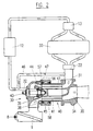
- FIG. 1 For the sake of simplicity, the processing according to FIG. 1 a pressure wave cycle shown and described while a two-cycle machine is shown in FIGS is.
- the invention is based on the number of pressure wave cycles regardless, it can be used for pressure wave machines with only one cycle or with two or more cycles become.
- Figure 1 shows a development of the rotor Pressure wave machine according to the prior art and you can see the internal combustion engine 1, the gas dynamic Pressure wave machine 2, the high pressure exhaust duct 3 and Low-pressure exhaust duct 4 including the purge air S, the rotor 6 with the individual cells 18, the fresh air inlet 8, or low-pressure fresh air supply duct 14, the high-pressure charge air duct 10, which merges into the charge air duct 11 and leads to the internal combustion engine 1.
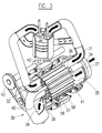
- FIG. 2 and 3 is an inventive Gas-dynamic pressure wave machine shown on the one Plenty of improvements have been made to overall to increase the efficiency significantly.
- the Pressure wave machine 30 is via the high-pressure exhaust duct 31 and the high pressure charge air duct 32 with the schematic shown internal combustion engine 33 connected.
- in the Gas housing 34 is also the low pressure exhaust duct 35, and it can be seen from this figure that the two channels, d. H. the high pressure exhaust duct and the Low-pressure exhaust duct, in the gas housing on the rotor side as sector-shaped openings, each with an opening edge 36, or 37 lead.
- the rotor 40 can also be seen with its Cells 41, the rotor being arranged in a jacket 42 and driven, for example, by a belt drive 43 becomes.
- the pressure wave machine is an open system, and that means that between the exhaust part and the Fresh air section a direct connection via the rotor consists. This also causes the engine pressure pulsations from the exhaust gas high pressure section to the fresh air high pressure section transfer.
- the connecting line 46, the High-pressure charge air duct 32 into the high-pressure exhaust duct 31 leads.
- the connecting line contains a Check valve 47, optionally with a electronic control is provided. It works Check valve as a regulation in the sense that only Pressure surges are transmitted, their energetic level is higher than the current pressure in the high-pressure exhaust duct.
- Branch that in Figure 2 or 3 somewhere between the High pressure charge air duct edge and the engine intake is arranged, directly after the opening edge of the high-pressure charge air duct is arranged.
- This variant is the Not shown for clarity.
- the pressure wave machine is after State of the art heavily dependent on filling.
- Reduction of pressure pulsations as described above allows the provision of a connecting line Return of charge air to the high pressure exhaust side of the Pressure wave machine, thereby increasing the Mass throughput of the machine and thus an increase in Fill levels, which results in a significant increase in pressure noticeable.
- An additional regulation of the returned Fresh air high pressure volume by means of the regulated Check valve can therefore be used to control the charge pressure in the general and in addition to the Otto engine Power control can be used.
- the pressure wave machine to improve compression efficiency at higher Engine throughputs can be dimensioned somewhat larger, without increasing the boost pressure at lower engine throughputs to lose.
- This can also be done, for example, by that the cross section of the connecting channel by means of a suitable, known device is regulated, wherein either the regulated check valve or one additional cross-sectional control can be used. This is particularly effective in the lower to middle Speed, temperature and load range of the Combustion engine.
Landscapes
- Engineering & Computer Science (AREA)
- Chemical & Material Sciences (AREA)
- Mechanical Engineering (AREA)
- General Engineering & Computer Science (AREA)
- Combustion & Propulsion (AREA)
- Health & Medical Sciences (AREA)
- Chemical Kinetics & Catalysis (AREA)
- Toxicology (AREA)
- Supercharger (AREA)
- Mechanical Treatment Of Semiconductor (AREA)
- Characterised By The Charging Evacuation (AREA)
- Motor Or Generator Frames (AREA)
Claims (5)
- Moteur à combustion interne avec machine à ondes de pression gazodynamique, la machine à ondes de pression étant destinée à amener l'air de charge au moteur à combustion interne et comprenant un rotor (6, 40) présentant des cellules (18, 41), un canal d'admission d'air frais à basse pression (14, 38), un canal d'air de charge à haute pression (10, 32) conduisant au moteur à combustion interne (1, 33), un canal des gaz d'échappement à haute pression (3, 31) en provenance du moteur à combustion interne et un canal des gaz d'échappement à basse pression (4, 35), le canal des gaz d'échappement à basse pression (4, 35) et le canal des gaz d'échappement à haute pression (3, 31) étant aménagés dans un carter à gaz (5, 34), et le canal d'amenée d'air frais à basse pression (14, 38) et le canal d'air de charge à haute pression (10, 32) étant aménagés dans un carter à air (15, 39), et une conduite de liaison (46) étant aménagée entre le canal d'air de charge à haute pression (32) et le canal des gaz d'échappement à haute pression (31), caractérisé en ce que seule la machine à ondes de pression est utilisée pour la suralimentation du moteur à combustion interne, et que la conduite de liaison (46) est munie d'une régulation d'écoulement pour éliminer des pulsations de pression nuisibles, augmenter le degré de remplissage résultant de la suralimentation et augmenter le rendement en compression.
- Machine à ondes de pression gazodynamique selon la revendication 1, caractérisée en ce que la conduite de liaison (46) comporte une soupape de non-retour (47) afin d'éviter une admission de gaz d'échappement à l'air de charge et afin de filtrer les pulsations de pression nuisibles.
- Machine à ondes de pression gazodynamique selon la revendication 2, caractérisée en ce que la soupape de non-retour (47) est commandée par l'intermédiaire d'un circuit électronique.
- Machine à ondes de pression gazodynamique selon l'une des revendications 1 à 3, caractérisée en ce que la section de la conduite de liaison (46) est variable au moyen d'un dispositif de régulation.
- Machine à ondes de pression gazodynamique selon l'une des revendications 1 à 4, caractérisée en ce que la conduite de liaison (46) bifurque près de l'arête d'ouverture du canal d'air de charge à haute pression (32).
Priority Applications (9)
| Application Number | Priority Date | Filing Date | Title |
|---|---|---|---|
| ES97810614T ES2225946T3 (es) | 1997-08-29 | 1997-08-29 | Maquina de onda de presion gasodinamica. |
| DE59711832T DE59711832D1 (de) | 1997-08-29 | 1997-08-29 | Gasdynamische Druckwellenmaschine |
| AT97810614T ATE272788T1 (de) | 1997-08-29 | 1997-08-29 | Gasdynamische druckwellenmaschine |
| EP97810614A EP0899434B1 (fr) | 1997-08-29 | 1997-08-29 | Machine à ondes de pression utilisant la dynamique des gaz |
| KR1020007002046A KR20010023404A (ko) | 1997-08-29 | 1998-08-25 | 가스-동압력 파형기 |
| PCT/EP1998/005379 WO1999011915A1 (fr) | 1997-08-29 | 1998-08-25 | Machine a ondes de pression gazodynamique |
| US09/486,452 US6314951B1 (en) | 1997-08-29 | 1998-08-25 | Gas-dynamic pressure-wave machine |
| AU95334/98A AU728535B2 (en) | 1997-08-29 | 1998-08-25 | Gas-dynamic pressure wave machine |
| JP2000508894A JP4190726B2 (ja) | 1997-08-29 | 1998-08-25 | 気体力学的圧力波機械 |
Applications Claiming Priority (1)
| Application Number | Priority Date | Filing Date | Title |
|---|---|---|---|
| EP97810614A EP0899434B1 (fr) | 1997-08-29 | 1997-08-29 | Machine à ondes de pression utilisant la dynamique des gaz |
Publications (2)
| Publication Number | Publication Date |
|---|---|
| EP0899434A1 EP0899434A1 (fr) | 1999-03-03 |
| EP0899434B1 true EP0899434B1 (fr) | 2004-08-04 |
Family
ID=8230359
Family Applications (1)
| Application Number | Title | Priority Date | Filing Date |
|---|---|---|---|
| EP97810614A Expired - Lifetime EP0899434B1 (fr) | 1997-08-29 | 1997-08-29 | Machine à ondes de pression utilisant la dynamique des gaz |
Country Status (9)
| Country | Link |
|---|---|
| US (1) | US6314951B1 (fr) |
| EP (1) | EP0899434B1 (fr) |
| JP (1) | JP4190726B2 (fr) |
| KR (1) | KR20010023404A (fr) |
| AT (1) | ATE272788T1 (fr) |
| AU (1) | AU728535B2 (fr) |
| DE (1) | DE59711832D1 (fr) |
| ES (1) | ES2225946T3 (fr) |
| WO (1) | WO1999011915A1 (fr) |
Families Citing this family (8)
| Publication number | Priority date | Publication date | Assignee | Title |
|---|---|---|---|---|
| DE10210358B4 (de) * | 2002-03-08 | 2013-08-22 | General Motors Llc ( N. D. Ges. D. Staates Delaware ) | Ein Brennstoffzellensystem mit Kompressor sowie Verfahren zum Betrieb eines solchen Brennstoffzellensystems |
| ATE306014T1 (de) | 2002-06-28 | 2005-10-15 | Verfahren zur regelung einer verbrennungsmaschine mit einer gasdynamischen druckwellenmaschine | |
| EP1375859B1 (fr) | 2002-06-28 | 2007-07-18 | Swissauto Engineering S.A. | Procédé de contrôle d'un moteur à combustion interne avec une machine à ondes de pression à dynamique des gaz |
| US7497666B2 (en) * | 2004-09-21 | 2009-03-03 | George Washington University | Pressure exchange ejector |
| FR2879250A1 (fr) * | 2004-12-09 | 2006-06-16 | Renault Sas | Dispositif de suralimentation d'air pour moteur a combustion interne avec recyclage de gaz d'echappement, et procede associe. |
| FR2879249A1 (fr) * | 2004-12-09 | 2006-06-16 | Renault Sas | Dispositif de suralimentation et de stratification de gaz d'echappement recycles pour moteur a combustion interne, notamment pour vehicule automobile, et procede associe. |
| DE102010008385A1 (de) * | 2010-02-17 | 2011-08-18 | Benteler Automobiltechnik GmbH, 33102 | Verfahren zur Einstellung eines Ladedruckes |
| JP5062334B2 (ja) * | 2010-04-20 | 2012-10-31 | トヨタ自動車株式会社 | 圧力波過給機 |
Family Cites Families (7)
| Publication number | Priority date | Publication date | Assignee | Title |
|---|---|---|---|---|
| JPS6128717A (ja) * | 1984-07-19 | 1986-02-08 | Mazda Motor Corp | 過給機付エンジン |
| US4702218A (en) * | 1984-07-24 | 1987-10-27 | Mazda Motor Corporation | Engine intake system having a pressure wave supercharger |
| EP0266636B1 (fr) * | 1986-10-29 | 1991-12-27 | Comprex Ag | Compresseur à ondes de pression |
| US4910959A (en) * | 1988-10-11 | 1990-03-27 | Pulso Catalytic Superchargers Corporation | Pulsed catalytic supercharger silencer |
| CH681738A5 (fr) | 1989-11-16 | 1993-05-14 | Comprex Ag | |
| US5284123A (en) * | 1993-01-22 | 1994-02-08 | Pulso Catalytic Superchargers | Pressure wave supercharger having a stationary cellular member |
| AT408785B (de) * | 1995-11-30 | 2002-03-25 | Blank Otto Ing | Aufladeeinrichtung für die ladeluft einer verbrennungskraftmaschine |
-
1997
- 1997-08-29 EP EP97810614A patent/EP0899434B1/fr not_active Expired - Lifetime
- 1997-08-29 DE DE59711832T patent/DE59711832D1/de not_active Expired - Lifetime
- 1997-08-29 ES ES97810614T patent/ES2225946T3/es not_active Expired - Lifetime
- 1997-08-29 AT AT97810614T patent/ATE272788T1/de active
-
1998
- 1998-08-25 KR KR1020007002046A patent/KR20010023404A/ko not_active Withdrawn
- 1998-08-25 US US09/486,452 patent/US6314951B1/en not_active Expired - Lifetime
- 1998-08-25 JP JP2000508894A patent/JP4190726B2/ja not_active Expired - Fee Related
- 1998-08-25 AU AU95334/98A patent/AU728535B2/en not_active Ceased
- 1998-08-25 WO PCT/EP1998/005379 patent/WO1999011915A1/fr not_active Ceased
Also Published As
| Publication number | Publication date |
|---|---|
| AU9533498A (en) | 1999-03-22 |
| DE59711832D1 (de) | 2004-09-09 |
| WO1999011915A1 (fr) | 1999-03-11 |
| ATE272788T1 (de) | 2004-08-15 |
| US6314951B1 (en) | 2001-11-13 |
| ES2225946T3 (es) | 2005-03-16 |
| EP0899434A1 (fr) | 1999-03-03 |
| KR20010023404A (ko) | 2001-03-26 |
| JP2001515172A (ja) | 2001-09-18 |
| AU728535B2 (en) | 2001-01-11 |
| JP4190726B2 (ja) | 2008-12-03 |
Similar Documents
| Publication | Publication Date | Title |
|---|---|---|
| DE69616932T2 (de) | Motorraumanordnung eines Fahrzeuges zum Einbringen von kaltem Ansaugluft | |
| DE69823039T2 (de) | Gasdynamische druckwellenmaschine | |
| EP0210328B1 (fr) | Turbochargeur pour un moteur à combustion interne avec un dispositif de commande de l'écoulement du gaz d'échappement à haute pression | |
| DE112009000075B4 (de) | Lufteinlasssystem mit Rückführkreis, Verfahren zum Halten eines Druckunterschieds und Leistungssystem | |
| DE3420015A1 (de) | Mehrzylinder-brennkraftmaschine mit zwei abgasturboladern | |
| EP0899434B1 (fr) | Machine à ondes de pression utilisant la dynamique des gaz | |
| CH665879A5 (de) | Kolbenbrennkraftmaschine. | |
| DE102011006117A1 (de) | Luftansaugvorrichtung für ein Fahrzeug | |
| DE602004005292T2 (de) | Regeneration eines Dieselpartikelfilters | |
| WO2008155111A1 (fr) | Procédé et dispositif pour augmenter la puissance de freinage moteur d'un moteur à combustion interne à piston alternatif dans un véhicule, en particulier d'un moteur diesel | |
| DE2809202A1 (de) | Aufladesystem fuer einen mehrzylinder- verbrennungsmotor | |
| DE3532345A1 (de) | Verfahren und einrichtung zum betrieb eines dieselmotors mit abgaspartikelfilter | |
| DE2544471B2 (de) | Arbeitsraumbildende Brennkraftmaschine mit zwei oder mehreren in Reihe geschalteten Abgasturboladern | |
| DE102018106679B4 (de) | Verfahren zum Betreiben einer Brennkraftmaschine, Brennkraftmaschine und Kraftfahrzeug | |
| DE4212984A1 (de) | Kraftfahrzeug mit mittels abgasturbolader aufladbarer brennkraftmaschine und hydrostatisch-mechanischem antrieb der nebenaggregate | |
| DE3136830A1 (de) | Turbolader, insbesondere fuer motorraeder | |
| DE3439999C1 (de) | Viertakt-Brennkraftmaschine mit zwei Abgasturboladern | |
| DE60303249T2 (de) | Aufladevorrichtung für Brennkraftmaschinen | |
| DE3029973A1 (de) | Ansaugsystem fuer einen verbrennungsmotor | |
| CH619030A5 (en) | Exhaust turbocharger unit on a piston internal combustion engine | |
| DE19928523A1 (de) | Ottomotor sowie Verfahren zum Betreiben eines Ottomotors | |
| DE2542970A1 (de) | Aufgeladene brennkraftmaschine | |
| CH641877A5 (de) | Verfahren zur mehrstufigen verdichtung von gasen und mehrstufiger kompressor zur durchfuehrung des verfahrens. | |
| DE102009047355B4 (de) | Verbrennungsmaschine mit einem Gasspeicherraum mit variablem Volumen und Verfahren zum Betrieb einer solchen Verbrennungsmaschine | |
| DE69507717T2 (de) | Brennkraftmaschine |
Legal Events
| Date | Code | Title | Description |
|---|---|---|---|
| PUAI | Public reference made under article 153(3) epc to a published international application that has entered the european phase |
Free format text: ORIGINAL CODE: 0009012 |
|
| AK | Designated contracting states |
Kind code of ref document: A1 Designated state(s): AT CH DE ES FR GB IT LI SE |
|
| AX | Request for extension of the european patent |
Free format text: AL;LT;LV;RO;SI |
|
| 17P | Request for examination filed |
Effective date: 19990901 |
|
| AKX | Designation fees paid |
Free format text: AT CH DE ES FR GB IT LI SE |
|
| 17Q | First examination report despatched |
Effective date: 20010502 |
|
| GRAP | Despatch of communication of intention to grant a patent |
Free format text: ORIGINAL CODE: EPIDOSNIGR1 |
|
| GRAS | Grant fee paid |
Free format text: ORIGINAL CODE: EPIDOSNIGR3 |
|
| GRAA | (expected) grant |
Free format text: ORIGINAL CODE: 0009210 |
|
| AK | Designated contracting states |
Kind code of ref document: B1 Designated state(s): AT CH DE ES FR GB IT LI SE |
|
| REG | Reference to a national code |
Ref country code: GB Ref legal event code: FG4D Free format text: NOT ENGLISH |
|
| REG | Reference to a national code |
Ref country code: CH Ref legal event code: EP |
|
| REF | Corresponds to: |
Ref document number: 59711832 Country of ref document: DE Date of ref document: 20040909 Kind code of ref document: P |
|
| PG25 | Lapsed in a contracting state [announced via postgrant information from national office to epo] |
Ref country code: SE Free format text: LAPSE BECAUSE OF FAILURE TO SUBMIT A TRANSLATION OF THE DESCRIPTION OR TO PAY THE FEE WITHIN THE PRESCRIBED TIME-LIMIT Effective date: 20041104 |
|
| GBT | Gb: translation of ep patent filed (gb section 77(6)(a)/1977) |
Effective date: 20041125 |
|
| REG | Reference to a national code |
Ref country code: ES Ref legal event code: FG2A Ref document number: 2225946 Country of ref document: ES Kind code of ref document: T3 |
|
| ET | Fr: translation filed | ||
| PLBE | No opposition filed within time limit |
Free format text: ORIGINAL CODE: 0009261 |
|
| STAA | Information on the status of an ep patent application or granted ep patent |
Free format text: STATUS: NO OPPOSITION FILED WITHIN TIME LIMIT |
|
| 26N | No opposition filed |
Effective date: 20050506 |
|
| PGFP | Annual fee paid to national office [announced via postgrant information from national office to epo] |
Ref country code: ES Payment date: 20100825 Year of fee payment: 14 Ref country code: CH Payment date: 20100824 Year of fee payment: 14 |
|
| PGFP | Annual fee paid to national office [announced via postgrant information from national office to epo] |
Ref country code: AT Payment date: 20100812 Year of fee payment: 14 |
|
| PGFP | Annual fee paid to national office [announced via postgrant information from national office to epo] |
Ref country code: GB Payment date: 20100819 Year of fee payment: 14 |
|
| PGFP | Annual fee paid to national office [announced via postgrant information from national office to epo] |
Ref country code: IT Payment date: 20110823 Year of fee payment: 15 |
|
| REG | Reference to a national code |
Ref country code: CH Ref legal event code: PL |
|
| GBPC | Gb: european patent ceased through non-payment of renewal fee |
Effective date: 20110829 |
|
| PG25 | Lapsed in a contracting state [announced via postgrant information from national office to epo] |
Ref country code: CH Free format text: LAPSE BECAUSE OF NON-PAYMENT OF DUE FEES Effective date: 20110831 Ref country code: LI Free format text: LAPSE BECAUSE OF NON-PAYMENT OF DUE FEES Effective date: 20110831 |
|
| PG25 | Lapsed in a contracting state [announced via postgrant information from national office to epo] |
Ref country code: GB Free format text: LAPSE BECAUSE OF NON-PAYMENT OF DUE FEES Effective date: 20110829 |
|
| REG | Reference to a national code |
Ref country code: ES Ref legal event code: FD2A Effective date: 20121207 |
|
| REG | Reference to a national code |
Ref country code: AT Ref legal event code: MM01 Ref document number: 272788 Country of ref document: AT Kind code of ref document: T Effective date: 20110829 |
|
| PG25 | Lapsed in a contracting state [announced via postgrant information from national office to epo] |
Ref country code: AT Free format text: LAPSE BECAUSE OF NON-PAYMENT OF DUE FEES Effective date: 20110829 |
|
| PG25 | Lapsed in a contracting state [announced via postgrant information from national office to epo] |
Ref country code: ES Free format text: LAPSE BECAUSE OF NON-PAYMENT OF DUE FEES Effective date: 20110830 |
|
| PG25 | Lapsed in a contracting state [announced via postgrant information from national office to epo] |
Ref country code: IT Free format text: LAPSE BECAUSE OF NON-PAYMENT OF DUE FEES Effective date: 20120829 |
|
| REG | Reference to a national code |
Ref country code: FR Ref legal event code: PLFP Year of fee payment: 19 |
|
| PGFP | Annual fee paid to national office [announced via postgrant information from national office to epo] |
Ref country code: DE Payment date: 20150921 Year of fee payment: 19 |
|
| PGFP | Annual fee paid to national office [announced via postgrant information from national office to epo] |
Ref country code: FR Payment date: 20150820 Year of fee payment: 19 |
|
| REG | Reference to a national code |
Ref country code: DE Ref legal event code: R119 Ref document number: 59711832 Country of ref document: DE |
|
| REG | Reference to a national code |
Ref country code: FR Ref legal event code: ST Effective date: 20170428 |
|
| PG25 | Lapsed in a contracting state [announced via postgrant information from national office to epo] |
Ref country code: FR Free format text: LAPSE BECAUSE OF NON-PAYMENT OF DUE FEES Effective date: 20160831 Ref country code: DE Free format text: LAPSE BECAUSE OF NON-PAYMENT OF DUE FEES Effective date: 20170301 |