EP0899434B1 - Aerodyamic pressure wave machine - Google Patents
Aerodyamic pressure wave machine Download PDFInfo
- Publication number
- EP0899434B1 EP0899434B1 EP97810614A EP97810614A EP0899434B1 EP 0899434 B1 EP0899434 B1 EP 0899434B1 EP 97810614 A EP97810614 A EP 97810614A EP 97810614 A EP97810614 A EP 97810614A EP 0899434 B1 EP0899434 B1 EP 0899434B1
- Authority
- EP
- European Patent Office
- Prior art keywords
- pressure
- wave machine
- pressure wave
- channel
- gas
- Prior art date
- Legal status (The legal status is an assumption and is not a legal conclusion. Google has not performed a legal analysis and makes no representation as to the accuracy of the status listed.)
- Expired - Lifetime
Links
Images

Classifications
-
- F—MECHANICAL ENGINEERING; LIGHTING; HEATING; WEAPONS; BLASTING
- F02—COMBUSTION ENGINES; HOT-GAS OR COMBUSTION-PRODUCT ENGINE PLANTS
- F02B—INTERNAL-COMBUSTION PISTON ENGINES; COMBUSTION ENGINES IN GENERAL
- F02B33/00—Engines characterised by provision of pumps for charging or scavenging
- F02B33/02—Engines with reciprocating-piston pumps; Engines with crankcase pumps
-
- F—MECHANICAL ENGINEERING; LIGHTING; HEATING; WEAPONS; BLASTING
- F04—POSITIVE - DISPLACEMENT MACHINES FOR LIQUIDS; PUMPS FOR LIQUIDS OR ELASTIC FLUIDS
- F04F—PUMPING OF FLUID BY DIRECT CONTACT OF ANOTHER FLUID OR BY USING INERTIA OF FLUID TO BE PUMPED; SIPHONS
- F04F13/00—Pressure exchangers
-
- F—MECHANICAL ENGINEERING; LIGHTING; HEATING; WEAPONS; BLASTING
- F01—MACHINES OR ENGINES IN GENERAL; ENGINE PLANTS IN GENERAL; STEAM ENGINES
- F01N—GAS-FLOW SILENCERS OR EXHAUST APPARATUS FOR MACHINES OR ENGINES IN GENERAL; GAS-FLOW SILENCERS OR EXHAUST APPARATUS FOR INTERNAL-COMBUSTION ENGINES
- F01N3/00—Exhaust or silencing apparatus having means for purifying, rendering innocuous, or otherwise treating exhaust
- F01N3/08—Exhaust or silencing apparatus having means for purifying, rendering innocuous, or otherwise treating exhaust for rendering innocuous
- F01N3/10—Exhaust or silencing apparatus having means for purifying, rendering innocuous, or otherwise treating exhaust for rendering innocuous by thermal or catalytic conversion of noxious components of exhaust
- F01N3/18—Exhaust or silencing apparatus having means for purifying, rendering innocuous, or otherwise treating exhaust for rendering innocuous by thermal or catalytic conversion of noxious components of exhaust characterised by methods of operation; Control
- F01N3/22—Control of additional air supply only, e.g. using by-passes or variable air pump drives
-
- F—MECHANICAL ENGINEERING; LIGHTING; HEATING; WEAPONS; BLASTING
- F02—COMBUSTION ENGINES; HOT-GAS OR COMBUSTION-PRODUCT ENGINE PLANTS
- F02B—INTERNAL-COMBUSTION PISTON ENGINES; COMBUSTION ENGINES IN GENERAL
- F02B33/00—Engines characterised by provision of pumps for charging or scavenging
- F02B33/32—Engines with pumps other than of reciprocating-piston type
- F02B33/42—Engines with pumps other than of reciprocating-piston type with driven apparatus for immediate conversion of combustion gas pressure into pressure of fresh charge, e.g. with cell-type pressure exchangers
-
- F—MECHANICAL ENGINEERING; LIGHTING; HEATING; WEAPONS; BLASTING
- F01—MACHINES OR ENGINES IN GENERAL; ENGINE PLANTS IN GENERAL; STEAM ENGINES
- F01N—GAS-FLOW SILENCERS OR EXHAUST APPARATUS FOR MACHINES OR ENGINES IN GENERAL; GAS-FLOW SILENCERS OR EXHAUST APPARATUS FOR INTERNAL-COMBUSTION ENGINES
- F01N3/00—Exhaust or silencing apparatus having means for purifying, rendering innocuous, or otherwise treating exhaust
- F01N3/08—Exhaust or silencing apparatus having means for purifying, rendering innocuous, or otherwise treating exhaust for rendering innocuous
- F01N3/10—Exhaust or silencing apparatus having means for purifying, rendering innocuous, or otherwise treating exhaust for rendering innocuous by thermal or catalytic conversion of noxious components of exhaust
- F01N3/24—Exhaust or silencing apparatus having means for purifying, rendering innocuous, or otherwise treating exhaust for rendering innocuous by thermal or catalytic conversion of noxious components of exhaust characterised by constructional aspects of converting apparatus
- F01N3/30—Arrangements for supply of additional air
Definitions
- the present invention relates to a gas dynamic pressure wave machine according to the preamble of independent claim.
- Pressure wave machine is known from the prior art for example from WO-97 20134 A, the one Connection line between the high pressure charge air duct and the high pressure exhaust duct disclosed in the context of a heater for preheating the pressure wave machine serves.
- Equal pressure system delivers good efficiencies before the Pressure wave machine a volume in the exhaust manifold integrated to dampen the engine pulsations. Without these The hard engine pulsations would dampen above all lower engine speeds through the exhaust duct of the Penetrate the gas casing of the pressure wave machine into the rotor and the actual pressure wave process of Pressure wave machine interfere, which can be seen in a clear Degradation of efficiency and increased Recirculation noticeable. That in the exhaust collector before Pressure wave machine integrated, relatively large volume can only dampen part of these pulsations, not but to eliminate. Such an exhaust manifold volume also has the disadvantage of the larger volume and the greater heat capacity.
- the standard pressure wave machine is for high boost pressures and good efficiencies strongly dependent on filling.
- At deep Internal combustion engine throughput decreases the filling in the rotor of the Pressure wave machine and thus also the boost pressure.
- the The machine is actually too big in this map area. With a high internal combustion engine throughput, the filling increases strongly and the compression efficiency deteriorates yourself.
- the pressure wave machine is in this map area actually too small.
- FIG. 1 For the sake of simplicity, the processing according to FIG. 1 a pressure wave cycle shown and described while a two-cycle machine is shown in FIGS is.
- the invention is based on the number of pressure wave cycles regardless, it can be used for pressure wave machines with only one cycle or with two or more cycles become.
- Figure 1 shows a development of the rotor Pressure wave machine according to the prior art and you can see the internal combustion engine 1, the gas dynamic Pressure wave machine 2, the high pressure exhaust duct 3 and Low-pressure exhaust duct 4 including the purge air S, the rotor 6 with the individual cells 18, the fresh air inlet 8, or low-pressure fresh air supply duct 14, the high-pressure charge air duct 10, which merges into the charge air duct 11 and leads to the internal combustion engine 1.
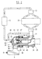
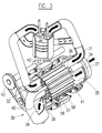
- FIG. 2 and 3 is an inventive Gas-dynamic pressure wave machine shown on the one Plenty of improvements have been made to overall to increase the efficiency significantly.
- the Pressure wave machine 30 is via the high-pressure exhaust duct 31 and the high pressure charge air duct 32 with the schematic shown internal combustion engine 33 connected.
- in the Gas housing 34 is also the low pressure exhaust duct 35, and it can be seen from this figure that the two channels, d. H. the high pressure exhaust duct and the Low-pressure exhaust duct, in the gas housing on the rotor side as sector-shaped openings, each with an opening edge 36, or 37 lead.
- the rotor 40 can also be seen with its Cells 41, the rotor being arranged in a jacket 42 and driven, for example, by a belt drive 43 becomes.
- the pressure wave machine is an open system, and that means that between the exhaust part and the Fresh air section a direct connection via the rotor consists. This also causes the engine pressure pulsations from the exhaust gas high pressure section to the fresh air high pressure section transfer.
- the connecting line 46, the High-pressure charge air duct 32 into the high-pressure exhaust duct 31 leads.
- the connecting line contains a Check valve 47, optionally with a electronic control is provided. It works Check valve as a regulation in the sense that only Pressure surges are transmitted, their energetic level is higher than the current pressure in the high-pressure exhaust duct.
- Branch that in Figure 2 or 3 somewhere between the High pressure charge air duct edge and the engine intake is arranged, directly after the opening edge of the high-pressure charge air duct is arranged.
- This variant is the Not shown for clarity.
- the pressure wave machine is after State of the art heavily dependent on filling.
- Reduction of pressure pulsations as described above allows the provision of a connecting line Return of charge air to the high pressure exhaust side of the Pressure wave machine, thereby increasing the Mass throughput of the machine and thus an increase in Fill levels, which results in a significant increase in pressure noticeable.
- An additional regulation of the returned Fresh air high pressure volume by means of the regulated Check valve can therefore be used to control the charge pressure in the general and in addition to the Otto engine Power control can be used.
- the pressure wave machine to improve compression efficiency at higher Engine throughputs can be dimensioned somewhat larger, without increasing the boost pressure at lower engine throughputs to lose.
- This can also be done, for example, by that the cross section of the connecting channel by means of a suitable, known device is regulated, wherein either the regulated check valve or one additional cross-sectional control can be used. This is particularly effective in the lower to middle Speed, temperature and load range of the Combustion engine.
Landscapes
- Engineering & Computer Science (AREA)
- Chemical & Material Sciences (AREA)
- Mechanical Engineering (AREA)
- General Engineering & Computer Science (AREA)
- Combustion & Propulsion (AREA)
- Health & Medical Sciences (AREA)
- Chemical Kinetics & Catalysis (AREA)
- Toxicology (AREA)
- Supercharger (AREA)
- Mechanical Treatment Of Semiconductor (AREA)
- Characterised By The Charging Evacuation (AREA)
- Motor Or Generator Frames (AREA)
Abstract
Description
Die vorliegende Erfindung bezieht sich auf eine gasdynamische Druckwellenmaschine gemäss dem Oberbegriff des unabhängigen Patentanspruchs. Eine solche Druckwellenmaschine ist aus dem Stand der Technik bekannt, beispielsweise aus der WO-97 20134 A, die eine Verbindungsleitung zwischen dem Hochdruck-Ladeluftkanal und dem Hochdruck-Abgaskanal offenbart, die im Zusammenhang mit einer Heizeinrichtung dem Vorheizen der Druckwellenmaschine dient.The present invention relates to a gas dynamic pressure wave machine according to the preamble of independent claim. Such Pressure wave machine is known from the prior art for example from WO-97 20134 A, the one Connection line between the high pressure charge air duct and the high pressure exhaust duct disclosed in the context of a heater for preheating the pressure wave machine serves.
Da die Druckwellenmaschine nach Stand der Technik konzeptbedingt nur mit einem möglichst pulsationsfreien Gleichdrucksystem gute Wirkungsgrade liefert, wird vor der Druckwellenmaschine ein Volumen in den Abgassammler integriert, um die Motorpulsationen zu dämpfen. Ohne diese Dämpfung würden die harten Motorpulsationen vor allem bei tieferen Motordrehzahlen durch den Abgaskanal des Gasgehäuses der Druckwellenmaschine in den Rotor eindringen und den eigentlichen Druckwellenprozess der Druckwellenmaschine stören, was sich in einer deutlichen Verschlechterung der Wirkungsgrade und erhöhter Rezirkulation bemerkbar macht. Das im Abgassammler vor der Druckwellenmaschine integrierte, relativ grosse Volumen vermag nur einen Teil dieser Pulsationen zu dämpfen, nicht aber zu beseitigen. Ebenso hat ein solches Abgassammler-Volumen den Nachteil des grösseren Bauvolumens und der grösseren Wärmekapazität.Because the pressure wave machine according to the prior art conceptually only with a pulsation-free as possible Equal pressure system delivers good efficiencies before the Pressure wave machine a volume in the exhaust manifold integrated to dampen the engine pulsations. Without these The hard engine pulsations would dampen above all lower engine speeds through the exhaust duct of the Penetrate the gas casing of the pressure wave machine into the rotor and the actual pressure wave process of Pressure wave machine interfere, which can be seen in a clear Degradation of efficiency and increased Recirculation noticeable. That in the exhaust collector before Pressure wave machine integrated, relatively large volume can only dampen part of these pulsations, not but to eliminate. Such an exhaust manifold volume also has the disadvantage of the larger volume and the greater heat capacity.
Die Standard-Druckwellenmaschine ist für hohe Ladedrücke und gute Wirkungsgrade stark füllungsabhängig. Bei tiefem Vebrennungsmotor-Durchsatz sinkt die Füllung im Rotor der Druckwellenmaschine und somit auch der Ladedruck. Die Maschine ist in diesem Kennfeldbereich eigentlich zu gross. Bei hohem Verbrennungsmotor-Durchsatz steigt die Füllung stark an und der Kompressionswirkungsgrad verschlechtert sich. In diesem Kennfeldbereich ist die Druckwellenmaschine also eigentlich zu klein. The standard pressure wave machine is for high boost pressures and good efficiencies strongly dependent on filling. At deep Internal combustion engine throughput decreases the filling in the rotor of the Pressure wave machine and thus also the boost pressure. The The machine is actually too big in this map area. With a high internal combustion engine throughput, the filling increases strongly and the compression efficiency deteriorates yourself. The pressure wave machine is in this map area actually too small.
Es ist von diesem Stand der Technik ausgehend Aufgabe der vorliegenden Erfindung eine Druckwellenmaschine anzugeben, die bei kleinerem Abgassammler-Volumen die schädlichen Pulsationen beseitigt und den Kompressions-Wirkungsgrad erhöht. Diese Aufgabe wird mit einer Druckwellenmaschine nach Anspruch 1 gelöst.Starting from this prior art, it is the task of present invention to provide a pressure wave machine, which are the harmful ones with a smaller exhaust gas collector volume Eliminates pulsations and compression efficiency elevated. This task is done with a pressure wave machine solved according to claim 1.
Weitere Vorteile und Ausführungsbeispiele der erfindungsgemassen Druckwellenmaschine sind in den abhängigen Ansprüchen definiert.Further advantages and embodiments of the Pressure wave machine according to the invention are in the dependent claims defined.
Die Erfindung wird im folgenden anhand einer Zeichnung von Ausfuhrungsbeispielen näher erlautert.
- Figur 1
- zeigt schematisch einen abgewickelten zylindrischen Schnitt durch die Zellen eines Rotors einer Druckwellenmaschine gemäss Stand der Technik,
Figur 2- zeigt eine allgemeine Darstellung einer erfindungsgemassen gasdynamischen Druckwellenmaschine, und
Figur 3- zeigt in perspektivischer Sicht die
gasdynamische Druckwellenmaschine gemäss
Figur 2.
- Figure 1
- schematically shows a developed cylindrical section through the cells of a rotor of a pressure wave machine according to the prior art,
- Figure 2
- shows a general representation of a gas dynamic pressure wave machine according to the invention, and
- Figure 3
- shows a perspective view of the gas dynamic pressure wave machine according to FIG. 2.
Der Einfachheit halber ist in der Abwicklung gemäss Figur 1 ein Druckwellen-Zyklus dargestellt und beschrieben, während in den Figuren 2 und 3 eine Zwei-Zyklusmaschine dargestellt ist. Die Erfindung ist jedoch von der Anzahl Druckwellen-Zyklen unabhängig, sie kann für Druckwellenmaschinen mit nur einem Zyklus oder aber mit zwei oder mehr Zyklen angewandt werden. For the sake of simplicity, the processing according to FIG. 1 a pressure wave cycle shown and described while a two-cycle machine is shown in FIGS is. However, the invention is based on the number of pressure wave cycles regardless, it can be used for pressure wave machines with only one cycle or with two or more cycles become.
Figur 1 zeigt eine Abwicklung des Rotors einer
Druckwellenmaschine gemäss Stand der Technik und man erkennt
die Verbrennungsmaschine 1, die gasdynamische
Druckwellenmaschine 2, den Hochdruck-Abgaskanal 3 und den
Niederdruck-Abgaskanal 4 inklusive der Spülluft S, den Rotor
6 mit den einzelnen Zellen 18, den Frischlufteintritt 8,
bzw. Niederdruck-Frischluftzufuhrkanal 14, den Hochdruck-Ladeluftkanal
10, der in den Ladeluftkanal 11 übergeht und
zur Verbrennungsmaschine 1 führt.Figure 1 shows a development of the rotor
Pressure wave machine according to the prior art and you can see
the internal combustion engine 1, the gas dynamic
In den Figuren 2 und 3 ist eine erfindungsgemässe
gasdynamische Druckwellenmaschine dargestellt, an der eine
Vielzahl von Verbesserungen durchgeführt worden sind, um
insgesamt den Wirkungsgrad wesentlich zu erhöhen. Die
Druckwellenmaschine 30 ist über den Hochdruck-Abgaskanal 31
und den Hochdruck-Ladeluftkanal 32 mit der schematisch
dargestellten Verbrennungsmaschine 33 verbunden. Im
Gasgehäuse 34 befindet sich ferner der Niederdruck-Abgaskanal
35, und es ist aus dieser Figur ersichtlich, dass
die beiden Kanäle, d. h. der Hochdruck-Abgaskanal und der
Niederdruck-Abgaskanal, im Gasgehäuse rotorseitig als
sektorförmige Oeffnungen mit je einer Oeffnungskante 36,
bzw. 37 münden. Man erkennt ferner den Rotor 40 mit seinen
Zellen 41, wobei der Rotor in einem Mantel 42 angeordnet ist
und beispielsweise durch einen Riemenantrieb 43 angetrieben
wird.In Figures 2 and 3 is an inventive
Gas-dynamic pressure wave machine shown on the one
Plenty of improvements have been made to
overall to increase the efficiency significantly. The
Wie bereits eingangs erwähnt, muss das für die vorbekannten Druckwellenmaschinen verwendete Abgassammler-Volumen zur Dämpfung der Motorpulsationen relativ gross sein und vermag trotzdem nicht die schädlichen Pulsationen zu beseitigen. Die Druckwellenmaschine stellt ein offenes System dar, und das heisst, dass zwischen dem Abgasteil und dem Frischluftteil eine direkte Verbindung über den Rotor besteht. Dadurch werden aber auch die Motordruckpulsationen vom Abgas-Hochdruckteil auf den Frischluft-Hochdruckteil übertragen.As already mentioned at the beginning, this has to be done for the previously known Pressure wave machines used exhaust gas collector volume for Damping of the motor pulsations can be relatively large and capable still not eliminate the harmful pulsations. The pressure wave machine is an open system, and that means that between the exhaust part and the Fresh air section a direct connection via the rotor consists. This also causes the engine pressure pulsations from the exhaust gas high pressure section to the fresh air high pressure section transfer.
Durch eine direkte Frischluftzuführung in den Abgaskanal
kann nun dieser Nachteil behoben werden. Man erkennt in den
Figuren 2 und 3 die Verbindungsleitung 46, die vom
Hochdruck-Ladeluftkanal 32 in den Hochdruck-Abgaskanal 31
führt. Dadurch werden die positiven Druckstösse im
Hochdruck-Ladeluftkanal auf den Hochdruck-Abgaskanal
übertragen. Die Verbindungsleitung enthält ein
Rückschlagventil 47, das gegebenenfalls mit einer
elektronischen Regelung versehen ist. Dabei wirkt das
Rückschlagventil als Regelung in dem Sinne, dass nur
Druckstösse übertragen werden, deren energetisches Niveau
höher liegt als der momentane Druck im Hochdruck-Abgaskanal.
Damit werden vor allem die negativen Druckpulse, d. h. der
Zustand des Quasi-Unterdruckes im Hochdruck-Abgaskanal,
angehoben und das gesamte Druckniveau sowohl innerhalb des
Hochdruck-Abgaskanals als auch des Hochdruck-Ladeluftkanals
durch die Glättung der negativen Druckpulse angehoben.
Dadurch kann das Druckniveau im Rotor vor dem Öffnen des
Hochdruck-Abgaskanals deutlich angehoben werden, und die von
dort eintreffenden Pulsationen werden gedämpft. Ausserdem
verringert diese Massnahme die Einströmverluste des heissen
Abgases in den Rotor, da der ganze Prozess gedämpft wird.Through a direct fresh air supply into the exhaust duct
this disadvantage can now be eliminated. One recognizes in the
Figures 2 and 3, the connecting
Eine weitere Verbesserung kann erzielt werden, falls die Abzweigung, die in Figur 2 oder 3 irgendwo zwischen der Hochdruck-Ladeluftkanal-Kante und dem Motoreinlass angeordnet ist, direkt nach der Offnungskante des Hochdruck-Ladeluftkanals angeordnet wird. Diese Variante ist der Übersichtlichkeit halber nicht eingezeichnet. A further improvement can be achieved if the Branch that in Figure 2 or 3 somewhere between the High pressure charge air duct edge and the engine intake is arranged, directly after the opening edge of the high-pressure charge air duct is arranged. This variant is the Not shown for clarity.
Wie bereits erwähnt wurde, ist die Druckwellenmaschine nach Stand der Technik stark füllungsabhängig. Zusätzlich zur Reduzierung der Druckpulsationen, wie oben beschrieben, erlaubt das Vorsehen einer Verbindungsleitung die Rückführung von Ladeluft auf die Hochdruck-Abgasseite der Druckwellenmaschine, dadurch eine Erhöhung des Massendurchsatzes der Maschine und somit eine Erhöhung des Füllgrades, was sich in einer deutlichen Drucksteigerung bemerkbar macht. Eine zusätzliche Regelung der ruckgeführten Frischluft-Hochdruckmenge mittels dem geregelten Rückschlagventil kann somit zur Ladedruckregelung im allgemeinen und beim Otto-Motor zusatzlich zur Leistungsregelung verwendet werden.As already mentioned, the pressure wave machine is after State of the art heavily dependent on filling. In addition to Reduction of pressure pulsations as described above allows the provision of a connecting line Return of charge air to the high pressure exhaust side of the Pressure wave machine, thereby increasing the Mass throughput of the machine and thus an increase in Fill levels, which results in a significant increase in pressure noticeable. An additional regulation of the returned Fresh air high pressure volume by means of the regulated Check valve can therefore be used to control the charge pressure in the general and in addition to the Otto engine Power control can be used.
Das heisst mit anderen Worten, dass die Druckwellenmaschine zur Verbesserung des Kompressionswirkungsgrades bei höheren Motordurchsatzen etwas grosser dimensioniert werden kann, ohne bei tieferen Motordurchsatzen an Ladedruck zu verlieren. Dies kann beispielsweise auch dadurch geschehen, dass der Querschnitt des Verbindungskanals mittels einer geeigneten, bekannten Vorrichtung geregelt wird, wobei entweder das geregelte Rückschlagventil oder eine zusatzliche Querschnittsregelung eingesetzt werden kann. Dies ist besonders wirksam im unteren bis mittleren Drehzahl-, Temperatur- und Lastbereich des Verbrennungsmotors.In other words, that means the pressure wave machine to improve compression efficiency at higher Engine throughputs can be dimensioned somewhat larger, without increasing the boost pressure at lower engine throughputs to lose. This can also be done, for example, by that the cross section of the connecting channel by means of a suitable, known device is regulated, wherein either the regulated check valve or one additional cross-sectional control can be used. This is particularly effective in the lower to middle Speed, temperature and load range of the Combustion engine.
Claims (5)
- Internal combustion engine with gas-dynamic pressure wave machine, the pressure wave machine being intended for supplying the internal combustion engine with charge air and comprising a rotor (6, 40) with cells (18, 41), a low pressure fresh air inlet channel (14, 38), a high pressure charge air channel (10, 32) leading to the internal combustion engine (1, 33), a high pressure exhaust channel (3, 31) coming from the internal combustion engine, and a low pressure exhaust channel (4, 35), the low pressure exhaust channel (4, 35) and the high pressure exhaust channel (3, 31) being enclosed in a gas housing (5, 34) and the low pressure fresh air inlet channel (14, 38) and the high pressure charge air channel (10, 32) being enclosed in an air housing (15, 39), and a connecting duct (46) being arranged between the high pressure charge air channel (32) and the high pressure exhaust channel (31), characterised in that only the pressure wave machine is used for supercharging the internal combustion engine, and in that the connecting duct (46) is provided with a flow regulation for eliminating detrimental engine pulsations, for increasing the charging filling degree, and for increasing the compression efficiency.
- Gas-dynamic pressure wave machine according to claim 1, characterised in that the connecting duct (46) comprises a nonreturn valve (47) in order to prevent an admission of exhaust gas to the charge air and to filter out the detrimental pressure pulsations.
- Gas-dynamic pressure wave machine according to claim 2, characterised in that the nonreturn valve (47) is controlled by an electronic circuit.
- Gas-dynamic pressure wave machine according to one of claims 1 to 3, characterised in that the cross-sectional area of the connecting duct (46) is variable by means of a regulating device.
- Gas-dynamic pressure wave machine according to one of claims 1 to 4, characterised in that the connecting duct (46) bifurcates near the opening edge of the high pressure charge air channel (32).
Priority Applications (9)
| Application Number | Priority Date | Filing Date | Title |
|---|---|---|---|
| ES97810614T ES2225946T3 (en) | 1997-08-29 | 1997-08-29 | GASODYNAMIC PRESSURE WAVE MACHINE. |
| DE59711832T DE59711832D1 (en) | 1997-08-29 | 1997-08-29 | Gas dynamic pressure wave machine |
| AT97810614T ATE272788T1 (en) | 1997-08-29 | 1997-08-29 | GAS-DYNAMIC PRESSURE WAVE MACHINE |
| EP97810614A EP0899434B1 (en) | 1997-08-29 | 1997-08-29 | Aerodyamic pressure wave machine |
| KR1020007002046A KR20010023404A (en) | 1997-08-29 | 1998-08-25 | Gas-dynamic pressure wave machine |
| PCT/EP1998/005379 WO1999011915A1 (en) | 1997-08-29 | 1998-08-25 | Gas-dynamic pressure-wave machine |
| US09/486,452 US6314951B1 (en) | 1997-08-29 | 1998-08-25 | Gas-dynamic pressure-wave machine |
| AU95334/98A AU728535B2 (en) | 1997-08-29 | 1998-08-25 | Gas-dynamic pressure wave machine |
| JP2000508894A JP4190726B2 (en) | 1997-08-29 | 1998-08-25 | Aerodynamic pressure wave machine |
Applications Claiming Priority (1)
| Application Number | Priority Date | Filing Date | Title |
|---|---|---|---|
| EP97810614A EP0899434B1 (en) | 1997-08-29 | 1997-08-29 | Aerodyamic pressure wave machine |
Publications (2)
| Publication Number | Publication Date |
|---|---|
| EP0899434A1 EP0899434A1 (en) | 1999-03-03 |
| EP0899434B1 true EP0899434B1 (en) | 2004-08-04 |
Family
ID=8230359
Family Applications (1)
| Application Number | Title | Priority Date | Filing Date |
|---|---|---|---|
| EP97810614A Expired - Lifetime EP0899434B1 (en) | 1997-08-29 | 1997-08-29 | Aerodyamic pressure wave machine |
Country Status (9)
| Country | Link |
|---|---|
| US (1) | US6314951B1 (en) |
| EP (1) | EP0899434B1 (en) |
| JP (1) | JP4190726B2 (en) |
| KR (1) | KR20010023404A (en) |
| AT (1) | ATE272788T1 (en) |
| AU (1) | AU728535B2 (en) |
| DE (1) | DE59711832D1 (en) |
| ES (1) | ES2225946T3 (en) |
| WO (1) | WO1999011915A1 (en) |
Families Citing this family (8)
| Publication number | Priority date | Publication date | Assignee | Title |
|---|---|---|---|---|
| DE10210358B4 (en) * | 2002-03-08 | 2013-08-22 | General Motors Llc ( N. D. Ges. D. Staates Delaware ) | A fuel cell system with compressor and method for operating such a fuel cell system |
| ATE306014T1 (en) | 2002-06-28 | 2005-10-15 | METHOD FOR CONTROLLING A COMBUSTION ENGINE USING A GAS-DYNAMIC PRESSURE WAVE ENGINE | |
| EP1375859B1 (en) | 2002-06-28 | 2007-07-18 | Swissauto Engineering S.A. | Method for controlling an internal combustion engine with a gas-dynamic pressure-wave machine |
| US7497666B2 (en) * | 2004-09-21 | 2009-03-03 | George Washington University | Pressure exchange ejector |
| FR2879250A1 (en) * | 2004-12-09 | 2006-06-16 | Renault Sas | AIR SUPPLY DEVICE FOR INTERNAL COMBUSTION ENGINE WITH EXHAUST GAS RECYCLING, AND ASSOCIATED METHOD. |
| FR2879249A1 (en) * | 2004-12-09 | 2006-06-16 | Renault Sas | RECYCLED EXHAUST GAS SUPPLY AND STRATIFICATION DEVICE FOR INTERNAL COMBUSTION ENGINE, IN PARTICULAR FOR MOTOR VEHICLE, AND ASSOCIATED METHOD. |
| DE102010008385A1 (en) * | 2010-02-17 | 2011-08-18 | Benteler Automobiltechnik GmbH, 33102 | Method for setting a boost pressure |
| JP5062334B2 (en) * | 2010-04-20 | 2012-10-31 | トヨタ自動車株式会社 | Pressure wave supercharger |
Family Cites Families (7)
| Publication number | Priority date | Publication date | Assignee | Title |
|---|---|---|---|---|
| JPS6128717A (en) * | 1984-07-19 | 1986-02-08 | Mazda Motor Corp | Engine with supercharger |
| US4702218A (en) * | 1984-07-24 | 1987-10-27 | Mazda Motor Corporation | Engine intake system having a pressure wave supercharger |
| EP0266636B1 (en) * | 1986-10-29 | 1991-12-27 | Comprex Ag | Pressure wave supercharger |
| US4910959A (en) * | 1988-10-11 | 1990-03-27 | Pulso Catalytic Superchargers Corporation | Pulsed catalytic supercharger silencer |
| CH681738A5 (en) | 1989-11-16 | 1993-05-14 | Comprex Ag | |
| US5284123A (en) * | 1993-01-22 | 1994-02-08 | Pulso Catalytic Superchargers | Pressure wave supercharger having a stationary cellular member |
| AT408785B (en) * | 1995-11-30 | 2002-03-25 | Blank Otto Ing | CHARGER FOR THE CHARGE AIR OF AN INTERNAL COMBUSTION ENGINE |
-
1997
- 1997-08-29 EP EP97810614A patent/EP0899434B1/en not_active Expired - Lifetime
- 1997-08-29 DE DE59711832T patent/DE59711832D1/en not_active Expired - Lifetime
- 1997-08-29 ES ES97810614T patent/ES2225946T3/en not_active Expired - Lifetime
- 1997-08-29 AT AT97810614T patent/ATE272788T1/en active
-
1998
- 1998-08-25 KR KR1020007002046A patent/KR20010023404A/en not_active Withdrawn
- 1998-08-25 US US09/486,452 patent/US6314951B1/en not_active Expired - Lifetime
- 1998-08-25 JP JP2000508894A patent/JP4190726B2/en not_active Expired - Fee Related
- 1998-08-25 AU AU95334/98A patent/AU728535B2/en not_active Ceased
- 1998-08-25 WO PCT/EP1998/005379 patent/WO1999011915A1/en not_active Ceased
Also Published As
| Publication number | Publication date |
|---|---|
| AU9533498A (en) | 1999-03-22 |
| DE59711832D1 (en) | 2004-09-09 |
| WO1999011915A1 (en) | 1999-03-11 |
| ATE272788T1 (en) | 2004-08-15 |
| US6314951B1 (en) | 2001-11-13 |
| ES2225946T3 (en) | 2005-03-16 |
| EP0899434A1 (en) | 1999-03-03 |
| KR20010023404A (en) | 2001-03-26 |
| JP2001515172A (en) | 2001-09-18 |
| AU728535B2 (en) | 2001-01-11 |
| JP4190726B2 (en) | 2008-12-03 |
Similar Documents
| Publication | Publication Date | Title |
|---|---|---|
| DE69616932T2 (en) | Engine compartment arrangement of a vehicle for introducing cold intake air | |
| DE69823039T2 (en) | GAS DYNAMIC PRESSURE WAVE MACHINE | |
| EP0210328B1 (en) | Turbo charger for an internal-combustion engine comprising a controlling device for the high-pressure exhaust gas flow | |
| DE112009000075B4 (en) | Air intake system with return circuit, method of maintaining pressure differential and power system | |
| DE3420015A1 (en) | MULTI-CYLINDER INTERNAL COMBUSTION ENGINE WITH TWO EXHAUST TURBOCHARGERS | |
| EP0899434B1 (en) | Aerodyamic pressure wave machine | |
| CH665879A5 (en) | PISTON COMBUSTION ENGINE. | |
| DE102011006117A1 (en) | Air intake device for a vehicle | |
| DE602004005292T2 (en) | Regeneration of a diesel particulate filter | |
| WO2008155111A1 (en) | Method and device for increasing the engine brake power of a reciprocating piston internal combustion engine of a vehicle, particularly of a diesel engine | |
| DE2809202A1 (en) | CHARGING SYSTEM FOR A MULTICYLINDER COMBUSTION ENGINE | |
| DE3532345A1 (en) | METHOD AND DEVICE FOR OPERATING A DIESEL ENGINE WITH EXHAUST PARTICLE FILTER | |
| DE2544471B2 (en) | Internal combustion engine that forms a working space with two or more exhaust gas turbochargers connected in series | |
| DE102018106679B4 (en) | Method for operating an internal combustion engine, internal combustion engine and motor vehicle | |
| DE4212984A1 (en) | MOTOR VEHICLE WITH EXHAUST TURBOCHARGER RECHARGEABLE INTERNAL COMBUSTION ENGINE AND HYDROSTATIC-MECHANICAL DRIVE OF THE AUXILIARY UNITS | |
| DE3136830A1 (en) | TURBOCHARGER, ESPECIALLY FOR MOTORCYCLES | |
| DE3439999C1 (en) | Four-stroke internal combustion engine with two exhaust gas turbochargers | |
| DE60303249T2 (en) | Charging device for internal combustion engines | |
| DE3029973A1 (en) | INTAKE SYSTEM FOR A COMBUSTION ENGINE | |
| CH619030A5 (en) | Exhaust turbocharger unit on a piston internal combustion engine | |
| DE19928523A1 (en) | Otto engine esp. for cars has compressor connected with intake side to compressor side of turbocharger, and throttle valve between compressor intake and pressure sides | |
| DE2542970A1 (en) | CHARGED COMBUSTION ENGINE | |
| CH641877A5 (en) | METHOD FOR MULTI-STAGE COMPRESSION OF GASES AND MULTI-STAGE COMPRESSOR FOR CARRYING OUT THE METHOD. | |
| DE102009047355B4 (en) | Combustion engine with a gas storage space with variable volume and method for operating such an internal combustion engine | |
| DE69507717T2 (en) | INTERNAL COMBUSTION ENGINE |
Legal Events
| Date | Code | Title | Description |
|---|---|---|---|
| PUAI | Public reference made under article 153(3) epc to a published international application that has entered the european phase |
Free format text: ORIGINAL CODE: 0009012 |
|
| AK | Designated contracting states |
Kind code of ref document: A1 Designated state(s): AT CH DE ES FR GB IT LI SE |
|
| AX | Request for extension of the european patent |
Free format text: AL;LT;LV;RO;SI |
|
| 17P | Request for examination filed |
Effective date: 19990901 |
|
| AKX | Designation fees paid |
Free format text: AT CH DE ES FR GB IT LI SE |
|
| 17Q | First examination report despatched |
Effective date: 20010502 |
|
| GRAP | Despatch of communication of intention to grant a patent |
Free format text: ORIGINAL CODE: EPIDOSNIGR1 |
|
| GRAS | Grant fee paid |
Free format text: ORIGINAL CODE: EPIDOSNIGR3 |
|
| GRAA | (expected) grant |
Free format text: ORIGINAL CODE: 0009210 |
|
| AK | Designated contracting states |
Kind code of ref document: B1 Designated state(s): AT CH DE ES FR GB IT LI SE |
|
| REG | Reference to a national code |
Ref country code: GB Ref legal event code: FG4D Free format text: NOT ENGLISH |
|
| REG | Reference to a national code |
Ref country code: CH Ref legal event code: EP |
|
| REF | Corresponds to: |
Ref document number: 59711832 Country of ref document: DE Date of ref document: 20040909 Kind code of ref document: P |
|
| PG25 | Lapsed in a contracting state [announced via postgrant information from national office to epo] |
Ref country code: SE Free format text: LAPSE BECAUSE OF FAILURE TO SUBMIT A TRANSLATION OF THE DESCRIPTION OR TO PAY THE FEE WITHIN THE PRESCRIBED TIME-LIMIT Effective date: 20041104 |
|
| GBT | Gb: translation of ep patent filed (gb section 77(6)(a)/1977) |
Effective date: 20041125 |
|
| REG | Reference to a national code |
Ref country code: ES Ref legal event code: FG2A Ref document number: 2225946 Country of ref document: ES Kind code of ref document: T3 |
|
| ET | Fr: translation filed | ||
| PLBE | No opposition filed within time limit |
Free format text: ORIGINAL CODE: 0009261 |
|
| STAA | Information on the status of an ep patent application or granted ep patent |
Free format text: STATUS: NO OPPOSITION FILED WITHIN TIME LIMIT |
|
| 26N | No opposition filed |
Effective date: 20050506 |
|
| PGFP | Annual fee paid to national office [announced via postgrant information from national office to epo] |
Ref country code: ES Payment date: 20100825 Year of fee payment: 14 Ref country code: CH Payment date: 20100824 Year of fee payment: 14 |
|
| PGFP | Annual fee paid to national office [announced via postgrant information from national office to epo] |
Ref country code: AT Payment date: 20100812 Year of fee payment: 14 |
|
| PGFP | Annual fee paid to national office [announced via postgrant information from national office to epo] |
Ref country code: GB Payment date: 20100819 Year of fee payment: 14 |
|
| PGFP | Annual fee paid to national office [announced via postgrant information from national office to epo] |
Ref country code: IT Payment date: 20110823 Year of fee payment: 15 |
|
| REG | Reference to a national code |
Ref country code: CH Ref legal event code: PL |
|
| GBPC | Gb: european patent ceased through non-payment of renewal fee |
Effective date: 20110829 |
|
| PG25 | Lapsed in a contracting state [announced via postgrant information from national office to epo] |
Ref country code: CH Free format text: LAPSE BECAUSE OF NON-PAYMENT OF DUE FEES Effective date: 20110831 Ref country code: LI Free format text: LAPSE BECAUSE OF NON-PAYMENT OF DUE FEES Effective date: 20110831 |
|
| PG25 | Lapsed in a contracting state [announced via postgrant information from national office to epo] |
Ref country code: GB Free format text: LAPSE BECAUSE OF NON-PAYMENT OF DUE FEES Effective date: 20110829 |
|
| REG | Reference to a national code |
Ref country code: ES Ref legal event code: FD2A Effective date: 20121207 |
|
| REG | Reference to a national code |
Ref country code: AT Ref legal event code: MM01 Ref document number: 272788 Country of ref document: AT Kind code of ref document: T Effective date: 20110829 |
|
| PG25 | Lapsed in a contracting state [announced via postgrant information from national office to epo] |
Ref country code: AT Free format text: LAPSE BECAUSE OF NON-PAYMENT OF DUE FEES Effective date: 20110829 |
|
| PG25 | Lapsed in a contracting state [announced via postgrant information from national office to epo] |
Ref country code: ES Free format text: LAPSE BECAUSE OF NON-PAYMENT OF DUE FEES Effective date: 20110830 |
|
| PG25 | Lapsed in a contracting state [announced via postgrant information from national office to epo] |
Ref country code: IT Free format text: LAPSE BECAUSE OF NON-PAYMENT OF DUE FEES Effective date: 20120829 |
|
| REG | Reference to a national code |
Ref country code: FR Ref legal event code: PLFP Year of fee payment: 19 |
|
| PGFP | Annual fee paid to national office [announced via postgrant information from national office to epo] |
Ref country code: DE Payment date: 20150921 Year of fee payment: 19 |
|
| PGFP | Annual fee paid to national office [announced via postgrant information from national office to epo] |
Ref country code: FR Payment date: 20150820 Year of fee payment: 19 |
|
| REG | Reference to a national code |
Ref country code: DE Ref legal event code: R119 Ref document number: 59711832 Country of ref document: DE |
|
| REG | Reference to a national code |
Ref country code: FR Ref legal event code: ST Effective date: 20170428 |
|
| PG25 | Lapsed in a contracting state [announced via postgrant information from national office to epo] |
Ref country code: FR Free format text: LAPSE BECAUSE OF NON-PAYMENT OF DUE FEES Effective date: 20160831 Ref country code: DE Free format text: LAPSE BECAUSE OF NON-PAYMENT OF DUE FEES Effective date: 20170301 |