EP0898465B1 - A moisture transport system for contact electrocoagulation - Google Patents
A moisture transport system for contact electrocoagulation Download PDFInfo
- Publication number
- EP0898465B1 EP0898465B1 EP97917166A EP97917166A EP0898465B1 EP 0898465 B1 EP0898465 B1 EP 0898465B1 EP 97917166 A EP97917166 A EP 97917166A EP 97917166 A EP97917166 A EP 97917166A EP 0898465 B1 EP0898465 B1 EP 0898465B1
- Authority
- EP
- European Patent Office
- Prior art keywords
- electrode
- electrodes
- region
- ablation
- carrying member
- Prior art date
- Legal status (The legal status is an assumption and is not a legal conclusion. Google has not performed a legal analysis and makes no representation as to the accuracy of the status listed.)
- Expired - Lifetime
Links
- 238000009297 electrocoagulation Methods 0.000 title 1
- 238000002679 ablation Methods 0.000 claims abstract description 115
- 210000004291 uterus Anatomy 0.000 claims description 18
- 239000007788 liquid Substances 0.000 claims description 15
- 210000000746 body region Anatomy 0.000 claims description 6
- 238000005345 coagulation Methods 0.000 claims description 6
- 230000015271 coagulation Effects 0.000 claims description 6
- 239000004744 fabric Substances 0.000 claims description 6
- 210000001519 tissue Anatomy 0.000 description 55
- 238000000034 method Methods 0.000 description 20
- 210000000056 organ Anatomy 0.000 description 14
- 239000000463 material Substances 0.000 description 11
- 230000002357 endometrial effect Effects 0.000 description 9
- 239000012530 fluid Substances 0.000 description 9
- CURLTUGMZLYLDI-UHFFFAOYSA-N Carbon dioxide Chemical compound O=C=O CURLTUGMZLYLDI-UHFFFAOYSA-N 0.000 description 8
- 210000004696 endometrium Anatomy 0.000 description 8
- 239000007789 gas Substances 0.000 description 7
- 230000006835 compression Effects 0.000 description 6
- 238000007906 compression Methods 0.000 description 6
- 238000010438 heat treatment Methods 0.000 description 6
- 238000003780 insertion Methods 0.000 description 5
- 230000037431 insertion Effects 0.000 description 5
- 238000012544 monitoring process Methods 0.000 description 5
- 208000032843 Hemorrhage Diseases 0.000 description 4
- 208000034158 bleeding Diseases 0.000 description 4
- 230000000740 bleeding effect Effects 0.000 description 4
- 229910002092 carbon dioxide Inorganic materials 0.000 description 4
- 239000001569 carbon dioxide Substances 0.000 description 4
- 238000005286 illumination Methods 0.000 description 4
- 239000007787 solid Substances 0.000 description 4
- FAPWRFPIFSIZLT-UHFFFAOYSA-M Sodium chloride Chemical compound [Na+].[Cl-] FAPWRFPIFSIZLT-UHFFFAOYSA-M 0.000 description 3
- 230000008569 process Effects 0.000 description 3
- 210000002307 prostate Anatomy 0.000 description 3
- 238000007674 radiofrequency ablation Methods 0.000 description 3
- 230000000284 resting effect Effects 0.000 description 3
- 239000011780 sodium chloride Substances 0.000 description 3
- XLYOFNOQVPJJNP-UHFFFAOYSA-N water Substances O XLYOFNOQVPJJNP-UHFFFAOYSA-N 0.000 description 3
- 239000008280 blood Substances 0.000 description 2
- 210000004369 blood Anatomy 0.000 description 2
- 239000004020 conductor Substances 0.000 description 2
- 230000001276 controlling effect Effects 0.000 description 2
- 230000007423 decrease Effects 0.000 description 2
- 230000007246 mechanism Effects 0.000 description 2
- 230000037361 pathway Effects 0.000 description 2
- 230000002093 peripheral effect Effects 0.000 description 2
- BASFCYQUMIYNBI-UHFFFAOYSA-N platinum Chemical compound [Pt] BASFCYQUMIYNBI-UHFFFAOYSA-N 0.000 description 2
- 229920000742 Cotton Polymers 0.000 description 1
- 208000005189 Embolism Diseases 0.000 description 1
- BQCADISMDOOEFD-UHFFFAOYSA-N Silver Chemical compound [Ag] BQCADISMDOOEFD-UHFFFAOYSA-N 0.000 description 1
- 230000005856 abnormality Effects 0.000 description 1
- 230000004913 activation Effects 0.000 description 1
- 239000000853 adhesive Substances 0.000 description 1
- 230000001070 adhesive effect Effects 0.000 description 1
- 238000001574 biopsy Methods 0.000 description 1
- 230000015572 biosynthetic process Effects 0.000 description 1
- 210000001124 body fluid Anatomy 0.000 description 1
- 239000010839 body fluid Substances 0.000 description 1
- 230000001684 chronic effect Effects 0.000 description 1
- 230000001112 coagulating effect Effects 0.000 description 1
- 238000001816 cooling Methods 0.000 description 1
- 230000008878 coupling Effects 0.000 description 1
- 238000010168 coupling process Methods 0.000 description 1
- 238000005859 coupling reaction Methods 0.000 description 1
- 230000003247 decreasing effect Effects 0.000 description 1
- 238000000151 deposition Methods 0.000 description 1
- 230000008021 deposition Effects 0.000 description 1
- 230000001627 detrimental effect Effects 0.000 description 1
- 230000000694 effects Effects 0.000 description 1
- 238000000313 electron-beam-induced deposition Methods 0.000 description 1
- 230000008030 elimination Effects 0.000 description 1
- 238000003379 elimination reaction Methods 0.000 description 1
- 238000005516 engineering process Methods 0.000 description 1
- 239000000835 fiber Substances 0.000 description 1
- 238000011010 flushing procedure Methods 0.000 description 1
- 239000006260 foam Substances 0.000 description 1
- 239000006261 foam material Substances 0.000 description 1
- 210000000232 gallbladder Anatomy 0.000 description 1
- PCHJSUWPFVWCPO-UHFFFAOYSA-N gold Chemical compound [Au] PCHJSUWPFVWCPO-UHFFFAOYSA-N 0.000 description 1
- 229910052737 gold Inorganic materials 0.000 description 1
- 239000010931 gold Substances 0.000 description 1
- 230000023597 hemostasis Effects 0.000 description 1
- 238000003384 imaging method Methods 0.000 description 1
- 238000002357 laparoscopic surgery Methods 0.000 description 1
- 238000013532 laser treatment Methods 0.000 description 1
- 230000003902 lesion Effects 0.000 description 1
- 210000003101 oviduct Anatomy 0.000 description 1
- 239000002245 particle Substances 0.000 description 1
- 230000035699 permeability Effects 0.000 description 1
- 239000012466 permeate Substances 0.000 description 1
- 229910052697 platinum Inorganic materials 0.000 description 1
- 102000004169 proteins and genes Human genes 0.000 description 1
- 108090000623 proteins and genes Proteins 0.000 description 1
- 230000001105 regulatory effect Effects 0.000 description 1
- 239000000523 sample Substances 0.000 description 1
- 238000000926 separation method Methods 0.000 description 1
- 238000009958 sewing Methods 0.000 description 1
- 229910052709 silver Inorganic materials 0.000 description 1
- 239000004332 silver Substances 0.000 description 1
- 238000011282 treatment Methods 0.000 description 1
- 238000012800 visualization Methods 0.000 description 1
Images
Classifications
-
- A—HUMAN NECESSITIES
- A61—MEDICAL OR VETERINARY SCIENCE; HYGIENE
- A61B—DIAGNOSIS; SURGERY; IDENTIFICATION
- A61B18/00—Surgical instruments, devices or methods for transferring non-mechanical forms of energy to or from the body
- A61B18/04—Surgical instruments, devices or methods for transferring non-mechanical forms of energy to or from the body by heating
- A61B18/12—Surgical instruments, devices or methods for transferring non-mechanical forms of energy to or from the body by heating by passing a current through the tissue to be heated, e.g. high-frequency current
- A61B18/14—Probes or electrodes therefor
- A61B18/1485—Probes or electrodes therefor having a short rigid shaft for accessing the inner body through natural openings
-
- A—HUMAN NECESSITIES
- A61—MEDICAL OR VETERINARY SCIENCE; HYGIENE
- A61B—DIAGNOSIS; SURGERY; IDENTIFICATION
- A61B18/00—Surgical instruments, devices or methods for transferring non-mechanical forms of energy to or from the body
- A61B18/04—Surgical instruments, devices or methods for transferring non-mechanical forms of energy to or from the body by heating
- A61B18/12—Surgical instruments, devices or methods for transferring non-mechanical forms of energy to or from the body by heating by passing a current through the tissue to be heated, e.g. high-frequency current
-
- A—HUMAN NECESSITIES
- A61—MEDICAL OR VETERINARY SCIENCE; HYGIENE
- A61M—DEVICES FOR INTRODUCING MEDIA INTO, OR ONTO, THE BODY; DEVICES FOR TRANSDUCING BODY MEDIA OR FOR TAKING MEDIA FROM THE BODY; DEVICES FOR PRODUCING OR ENDING SLEEP OR STUPOR
- A61M16/00—Devices for influencing the respiratory system of patients by gas treatment, e.g. ventilators; Tracheal tubes
- A61M16/04—Tracheal tubes
- A61M16/0475—Tracheal tubes having openings in the tube
- A61M16/0477—Tracheal tubes having openings in the tube with incorporated means for delivering or removing fluids
- A61M16/0481—Tracheal tubes having openings in the tube with incorporated means for delivering or removing fluids through the cuff wall
-
- A—HUMAN NECESSITIES
- A61—MEDICAL OR VETERINARY SCIENCE; HYGIENE
- A61B—DIAGNOSIS; SURGERY; IDENTIFICATION
- A61B17/00—Surgical instruments, devices or methods
- A61B17/22—Implements for squeezing-off ulcers or the like on inner organs of the body; Implements for scraping-out cavities of body organs, e.g. bones; for invasive removal or destruction of calculus using mechanical vibrations; for removing obstructions in blood vessels, not otherwise provided for
- A61B2017/22051—Implements for squeezing-off ulcers or the like on inner organs of the body; Implements for scraping-out cavities of body organs, e.g. bones; for invasive removal or destruction of calculus using mechanical vibrations; for removing obstructions in blood vessels, not otherwise provided for with an inflatable part, e.g. balloon, for positioning, blocking, or immobilisation
-
- A—HUMAN NECESSITIES
- A61—MEDICAL OR VETERINARY SCIENCE; HYGIENE
- A61B—DIAGNOSIS; SURGERY; IDENTIFICATION
- A61B17/00—Surgical instruments, devices or methods
- A61B17/42—Gynaecological or obstetrical instruments or methods
- A61B2017/4216—Operations on uterus, e.g. endometrium
-
- A—HUMAN NECESSITIES
- A61—MEDICAL OR VETERINARY SCIENCE; HYGIENE
- A61B—DIAGNOSIS; SURGERY; IDENTIFICATION
- A61B18/00—Surgical instruments, devices or methods for transferring non-mechanical forms of energy to or from the body
- A61B18/04—Surgical instruments, devices or methods for transferring non-mechanical forms of energy to or from the body by heating
- A61B18/12—Surgical instruments, devices or methods for transferring non-mechanical forms of energy to or from the body by heating by passing a current through the tissue to be heated, e.g. high-frequency current
- A61B18/1206—Generators therefor
- A61B2018/1246—Generators therefor characterised by the output polarity
- A61B2018/126—Generators therefor characterised by the output polarity bipolar
-
- A—HUMAN NECESSITIES
- A61—MEDICAL OR VETERINARY SCIENCE; HYGIENE
- A61B—DIAGNOSIS; SURGERY; IDENTIFICATION
- A61B90/00—Instruments, implements or accessories specially adapted for surgery or diagnosis and not covered by any of the groups A61B1/00 - A61B50/00, e.g. for luxation treatment or for protecting wound edges
- A61B90/06—Measuring instruments not otherwise provided for
- A61B2090/064—Measuring instruments not otherwise provided for for measuring force, pressure or mechanical tension
- A61B2090/065—Measuring instruments not otherwise provided for for measuring force, pressure or mechanical tension for measuring contact or contact pressure
Definitions
- This invention relates to an ablation and/or coagulation apparatus for use in delivering energy to tissue for ablation, the apparatus comprising: an electrode carrying member; electrodes on the electrode carrying member; and a source of radio frequency energy coupled to the electrodes.
- Ablation of the interior lining of a body organ is a procedure which involves heating the organ lining to temperatures which destroy the cells of the lining or coagulate tissue proteins for hemostasis. Such a procedure may be performed as a treatment to one of many conditions, such as chronic bleeding of the endometrial layer of the uterus or abnormalities of the mucosal layer of the gallbladder.
- Existing methods for effecting ablation include circulation of heated fluid inside the organ (either directly or inside a balloon), laser treatment of the organ lining, and resistive heating using application of RF energy to the tissue to be ablated.
- U.S. Patent 5,084,044 describes an apparatus for endometrial ablation in which a balloon is inserted into the uterus. Heated fluid is then circulated through the balloon to expand the balloon into contact with the endometrium and to ablate the endometrium thermally.
- U.S. Patent 5,443,470 describes an apparatus for endometrial ablation in which an expandable balloon is provided with electrodes on its outer surface. After the apparatus is positioned inside the uterus, a non-conductive gas or liquid is used to fill the balloon, causing the balloon to push the electrodes into contact with the endometrial surface. RF energy is supplied to the electrodes to ablate the endometrial tissue using resistive heating.
- a similar apparatus is described with reference to Figure 13 of WO 95/32011.
- heated fluid method is a very passive and ineffective heating process which relies on the heat conductivity of the tissue. This process does not account for variations in factors such as the amount of contact between the balloon and the underlying tissue, or cooling effects such as those of blood circulating through the organ.
- RF ablation techniques can achieve more effective ablation since it relies on active heating of the tissue using RF energy, but presently the depth of ablation using RF techniques can only be estimated by a physician since no feedback can be provided as to actual ablation depth.
- U.S. Patent 5,505,730 describes an ablation apparatus of the kind defined hereinbefore at the beginning in which the electrode carrying member is in the form of a conforming member of conformable material such as a foam material, backed by a balloon.
- the electrodes are applied as an array to a conductive surface of the conforming member.
- An electrolytic fluid is pumped into the balloon and passes through apertures in the balloon into the conforming member through which it passes into the organ which is to be ablated.
- Radio frequency power is supplied through individual feed wires to the electrodes, so that radio frequency energy is delivered through electrodes and the electrolytic fluid to the inner surface of the organ which is to be ablated.
- US Patent 5 374 261 describes an ablation and/or coagulation apparatus in which electrodes in the form of electrically conductive solid branches extend angularly from a tubular electrically conductive trunk extending axially through a blunt-ended solid cylinder of sponge material.
- the solid branches terminate at tips at the peripheral surface of the sponge material.
- An electro-surgical probe can be passed through the tubular trunk such that a unipolar electro-surgical device is produced with multiple electrodes defined at the peripheral surface of the sponge material.
- This device is described as being useful for coagulating large surface areas such as cystic cavities or the endometrium of the uterus.
- the sponge material and the solid electrodes may be configured to conform to mate with an anatomical cavity.
- the electrode carrying member is substantially permeable to moisture and gases such as steam and conformable to the body cavity.
- Suctioning means are positioned within the electrode carrying member to aide the removal of moisture, and/or gas and/or liquid, present or generated during the ablation procedure.
- An array of electrodes is mounted to the surface of the electrode carrying member and arranged to produce ablation to a predetermined depth.
- the electrodes may be provided with means for variably controlling ablation depth by changing the electrode density or center to center spacing.
- an RF generator is used to deliver RF energy to the electrodes and to thereby induce current flow from the electrodes to tissue to be ablated.
- moisture such as steam or liquid
- the moisture permeability of the electrode carrying member allows the moisture to leave the ablation site so as to prevent the moisture from providing a path of conductivity for the current.
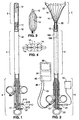
- an ablation device is comprised generally of three major components: RF applicator head 2, main body 4, and handle 6.
- Main body 4 includes a shaft 10.
- the RF applicator head 2 includes an electrode carrying means 12 mounted to the distal end of the shaft 10 and an array of electrodes 14 formed on the surface of the electrode carrying means 12.
- An RF generator 16 is electrically connected to the electrodes 14 to provide bipolar RF energy to them.
- Shaft 10 is an elongate member having a hollow interior. Shaft 10 is preferably 30.5 cm (12 inches) long and has a preferred cross-sectional diameter of approximately 4 mm. A collar 13 is formed on the exterior of the shaft 10 at the proximal end. As best shown in Figs. 6 and 7, passive spring members 15 are attached to the distal end of the shaft 10.
- a suction/insufflation tube 17 (Figs. 6-9) having a plurality of holes 17a formed in its distal end.
- An arched active spring member 19 is connected between the distal ends of the passive spring members 15 and the distal end of the suction/insufflation tube 17.
- electrode leads 18a and 18b extend through the shaft 10 from distal end 20 to proximal end 22 of the shaft 10. At the distal end 20 of the shaft 10, each of the leads 18a, 18b is coupled to a respective one of the electrodes 14. At the proximal end 22 of the shaft 10, the leads 18a, 18b are electrically connected to RF generator 16 via an electrical connector 21. During use, the leads 18a, 18b carry RF energy from the RF generator 16 to the electrodes. Each of the leads 18a, 18b is insulated and carries energy of an opposite polarity than the other lead.
- Electrode leads 23a, 23b also extend through the shaft 10.
- Contact sensors 25a, 25b are attached to the distal ends of the sensor leads 23a, 23b, respectively and are mounted to the electrode carrying means 12.
- the sensor leads 23a, 23b are coupled by the connector 21 to a monitoring module in the RF generator 16 which measures impedance between the sensors 25a, 25b.
- a reference pad may be positioned in contact with the patient and the impedance between one of the sensors and the reference pad measured.
- electrode leads 18a, 18b and sensor leads 23a, 23b extend through the shaft 10 between the external walls of the tube 17 and the interior walls of the shaft 10 and they are coupled to electrical connector 21 which is preferably mounted to the collar 13 on the shaft 10.
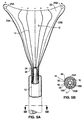
- Connector 21, which is connectable to the RF generator 16 includes at least four electrical contact rings 21a - 21d (Figs. 1 and 2) which correspond to each of the leads 18a, 18b, 23a, 23b.
- Rings 21a, 21b receive, from the RF generator, RF energy of positive and negative polarity, respectively.
- Rings 21c, 21d deliver signals from the right and left sensors, respectively, to a monitoring module within the RF generator 16.
- the electrode carrying means 12 is attached to the distal end 20 of the shaft 10.
- a plurality of holes 24 may be formed in the portion of the distal end 20 of the shaft which lies within the electrode carrying means 12.
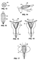
- the electrode carrying means 12 preferably has a shape which approximates the shape of the body organ which is to be ablated.
- the apparatus shown in Figs. 1 through 11 has a bicornual shape which is desirable for intrauterine ablation.
- the electrode carrying means 12 shown in these figures includes horn regions 26 which during use are positioned within the cornual regions of the uterus and which therefore extend towards the fallopian tubes.
- Electrode carrying means 12 is preferably a sack formed of a material which is non-conductive, which is permeable to moisture , and which may be compressed to a smaller volume and subsequently released to its natural size upon elimination of compression.
- Examples of preferred materials for the electrode carrying means include open cell sponge, foam, cotton, fabric, or cotton-like material, or any other material having the desired characteristics.
- the electrode carrying means may be formed of a metallized fabric.
- the term "pad" may be used interchangeably with the term electrode carrying means to refer to an electrode carrying means formed of any of the above materials or having the listed properties.
- Electrodes 14 are preferably attached to the outer surface of the electrode carrying means 12, such as by deposition or other attachment mechanism.
- the electrodes are preferably made of lengths of silver, gold, platinum, or any other conductive material.
- the electrodes may be attached to the electrode carrying means 12 by electron beam deposition, or they may be formed into coiled wires and bonded to the electrode carrying member using a flexible adhesive. Naturally, other means of attaching the electrodes, such as sewing them onto the surface of the carrying member, may alternatively be used. If the electrode carrying means 12 is formed of a metallized fabric, an insulating layer may be etched onto the fabric surface, leaving only the electrode regions exposed.
- the spacing between the electrodes i.e. the distance between the centers of adjacent electrodes
- the widths of the electrodes are selected so that ablation will reach predetermined depths within the tissue, particularly when maximum power is delivered through the electrodes (where maximum power is the level at which low impedance, low voltage ablation can be achieved).
- the depth of ablation is also effected by the electrode density (i.e., the percentage of the target tissue area which is in contact with active electrode surfaces) and may be regulated by pre-selecting the amount of this active electrode coverage. For example, the depth of ablation is much greater when the active electrode surface covers more than 10% of the target tissue than it is when the active electrode surfaces covers 1% of the target tissue.
- the electrodes 14A which have more active area in contact with the underlying tissue T, produce a region of ablation A that extends more deeply into the tissue T than the ablation region produced by the low density electrodes 14B, even though the electrode spacings and widths are the same for the high and low density electrodes.
- Electrode widths having spacings with more than 10% active electrode surface coverage, and their resultant ablation depth, based on an ablation area of 6 cm 2 and a power of 20 - 40 watts, are given on the following table: ELECTRODE WIDTH SPACING APPROX.
- Electrode widths having spacings with less than 1 % active electrode surface coverage, and their resultant ablation depth, based on an ablation area of 6 cm 2 and a power of 20 - 40 watts, are given on the following table: ELECTRODE WIDTH SPACING APPROX.
- the depth of ablation is significantly less when the active electrode surface coverage is decreased.
- the preferred electrode spacing is approximately 8 - 10 mm in the horn regions 26 with the active electrode surfaces covering approximately 1% of the target region. Approximately 1 - 2 mm electrode spacing (with 10% active electrode coverage) is preferred in the cervical region (designated 28) and approximately 3 - 6 mm (with greater than 10% active electrode surface coverage) is preferred in the main body region.
- the RF generator 16 may be configured to include a controller which gives the user a choice of which electrodes should be energized during a particular application in order to give the user control of ablation depth. For example, during an application for which deep ablation is desired, the user may elect to have the generator energize every other electrode, to thereby optimize the effective spacing of the electrodes and to decrease the percentage of active electrode surface coverage, as will be described below with respect to Fig. 18.
- the electrodes shown in the drawings are arranged in a particular pattern, it should be appreciated that the electrodes may be arranged in any pattern to provide ablation to desired depths.
- an introducer sheath 32 facilitates insertion of the apparatus into, and removal of the apparatus from, the body organ to be ablated.
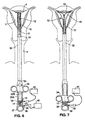
- the sheath 32 is a tubular member which is telescopically slidable over the shaft 10.
- the sheath 32 is slidable between a distal condition, shown in Fig. 6, in which the electrode carrying means 12 is compressed inside the sheath, and a proximal condition in which the sheath 32 is moved proximally to release the electrode carrying means from inside it (Fig. 7).
- a handle 34 attached to the sheath 32 provides finger holds to allow for manipulation of the sheath 32.
- Handle 34 is slidably mounted on a handle rail which includes a sleeve 33, a finger cutout 37, and a pair of spaced rails 35A, 35B extending between the sleeve 33 and the finger cutout 37.
- the shaft 10 and sheath 32 slidably extend through the sleeve 33 and between the rails 35A, 35B.
- the tube 17 also extends through the sleeve 33 and between the rails 35A, 35B, and its proximal end is fixed to the handle rail near the finger cutout 37.
- a compression spring 39 is disposed around the proximal most portion of the suction/insufflation tube 17 which lies between the rails 35A, 35B.
- One end of the compression spring 39 rests against the collar 13 on the shaft 10, while the opposite end of the compression spring rests against the handle rail 35.
- the sheath 32 is retracted from the electrode carrying means 12 by squeezing the handle 34 towards the finger cutout 37 to slide the sheath 32 in the distal direction.
- the shaft 10 (which is attached to the collar 13) is forced to slide in the proximal direction, causing compression of the spring 39 against the handle rail .
- the movement of the shaft 10 relative to the suction/insufflation tube 17 causes the shaft 10 to pull proximally on the passive spring members 15. Proximal movement of the passive spring members 15 in turn pulls against the active spring member 19, causing it to move to the opened condition shown in Fig. 7. Unless the shaft is held in this retracted condition, the compression spring 39 will push the collar and thus the shaft distally, forcing the RF applicator head to close.
- a locking mechanism (not shown) may be provided to hold the shaft in the fully withdrawn condition to prevent inadvertent closure of the spring members during the ablation procedure.
- the amount by which the springs 15, 19 are spread may be controlled by manipulating the handle 34 to slide the shaft 10 (via collar 13), proximally or distally. Such sliding movement of the shaft 10 causes forceps-like movement of the spring members 15, 19.
- a flow pathway 36 is formed in the handle rail and is fluidly coupled to a suction/insufflation port 38.
- the proximal end of the suction/insufflation tube 17 is fluidly coupled to the flow pathway so that gas fluid may be introduced into, or withdrawn from the suction/insufflation tube 17 via the suction/insufflation port 38.
- suction may be applied to the fluid port 38 using a suction/insufflation unit 40. This causes water vapor within the uterine cavity to pass through the permeable electrode carrying means 12, into the suction/insufflation tube 17 via holes 17A, through the tube 17, and through the suction/insufflation unit 40 via the port 38.
- insufflation gas such as carbon dioxide
- insufflation gas may be introduced into the suction/insufflation tube 17 via the port 38.
- the insufflation gas travels through the tube 17, through the holes 17A, and into the uterine cavity through the permeable electrode carrying member 12.
- lumens 42, 44, and 46 may be formed in the walls of the introducer sheath 32 as shown in Fig. 5B.
- An imaging conduit such as a fiberoptic cable 48, extends through lumen 42 and is coupled via a camera cable 43 to a camera 45. Images taken from the camera may be displayed on a monitor 56.
- An illumination fiber 50 extends through lumen 44 and is coupled to an illumination source 54.
- the third lumen 46 is an instrument channel through which surgical instruments may be introduced into the uterine cavity, if necessary.
- the electrode carrying means 12 may be provide to have additional components inside it that add structural integrity to the electrode carrying means when it is deployed within the body.
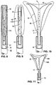
- alternative spring members 15a, 19a may be attached to the shaft 10 and biased such that, when in a resting state, the spring members are positioned in the fully resting condition shown in Fig. 11. Such spring members would spring to the resting condition upon withdrawal of the sheath 32 from the RF applicator head 2.
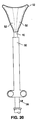
- a pair of inflatable balloons 52 may be arranged inside the electrode carrying means 12 as shown in Fig. 20 and connected to a tube (not shown) extending through the shaft 10 and into the balloons 52.
- the balloons 52 After insertion of the apparatus into the organ and following retraction of the sheath 32, the balloons 52 would be inflated by introduction of an inflation medium such as air into the balloons via a port similar to port 38 using an apparatus similar to the suction/insufflation apparatus 40.
- Structural integrity may also be added to the electrode carrying means through the application of suction to the proximal end 22 of the suction/insufflation tube 17.
- Application of suction using the suction/insufflation device 40 would draw the organ tissue towards the electrode carrying means 12 and thus into better contact with the electrodes 14.
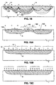
- Figs. 12 and 13 show an alternative embodiment of an ablation device according to the present invention.
- an electrode carrying means 1A is provided which has a shape which is generally tubular and thus is not specific to any particular organ shape.
- An ablation device having a general shape such as this may be used anywhere within the body where ablation or coagulation is needed.
- the alternative embodiment is useful for bleeding control during laparoscopic surgery (Fig. 14), tissue ablation in the prostate gland (Fig. 17), and also intrauterine ablation (Figs. 15 and 16).
- the device is initially configured for use by positioning the introducer sheath 32 distally along the shaft 10, such that it compresses the electrode carrying means 12 within its walls.
- the electrical connector 21 is connected to the RF generator 16, and the fiberoptic cable 48 and the illumination cable 50 are connected to the illumination source, monitor, and camera, 54, 56, 45.
- the suction/insufflation unit 40 is attached to suction/insufflation port 38 on the handle rail .
- the suction/insufflation unit 40 is preferably set to deliver carbon dioxide at an insufflation pressure of 20 - 200 mmHg.
- the distal end of the apparatus is inserted through the vaginal opening V and into the uterus U as shown in Fig. 6, until the distal end of the introducer sheath 32 contacts the fundus F of the uterus.
- carbon dioxide gas is introduced into the tube 17 via the port 38, and it enters the uterine cavity, thereby expanding the uterine cavity from a flat triangular shape to a 1-2 cm high triangular cavity.
- the physician may observe (using the camera 45 and monitor 56) the internal cavities using images detected by a fiberoptic cable 48 inserted through lumen 42. If, upon observation, the physician determines that a tissue biopsy or other procedure is needed, the required instruments may be inserted into the uterine cavity via the instrument channel 46.
- the handle 34 is withdrawn until it abuts the collar 13. At this point, the sheath 32 exposes the electrode carrying member 12 but the electrode carrying member 12 is not yet fully expanded (see Fig 9), because the spring members 15, 19 have not yet been moved to their open condition.
- the handle 34 is withdrawn further, causing the shaft 10 to move proximally relative to the suction/insufflation tube 17, causing the passive spring members 15 to pull the active spring members 19, causing them to open into the opened condition shown in Fig. 10.
- the physician may confirm proper positioning of the electrode carrying member 12 using the monitor 56, which displays images from the fiberoptic cable 48.
- the contact sensors 25A, 25B Proper positioning of the device and sufficient contact between the electrode carrying member 12 and the endometrium may further be confirmed using the contact sensors 25A, 25B.
- the monitoring module of the RF generator measures the impedance between these sensors using conventional means. If there is good contact between the sensors and the endometrium, the measured impedance will be approximately 20 - 180 ohm, depending on the water content of the endometrial lining.
- the sensors are positioned on the distal portions of the bicornual shaped electrode carrying member 12, which during use are positioned in the regions within the uterus in which it is most difficult to achieve good contact with the endometrium.
- an indication from the sensors 25A, 25B that there is sound contact between the sensors and the endometrial surface indicates that good electrode contact has been made with the endometrium.
- insufflation is terminated.
- Approximately 1 - 5 cc of saline may be introduced via suction/insufflation tube 17 to initially wet the electrodes and to improve electrode electrical contact with the tissue.
- the suction/insufflation device 40 is switched to a suctioning mode. As described above, the application of suction to the RF applicator head 2 via the suction/insufflation tube 17 collapses the uterine cavity onto the RF applicator head 2 and thus assures better contact between the electrodes and the endometrial tissue.
- the device is angled into contact with one side of the uterus during the ablation procedure. Once ablation is completed, the device (or a new device) is repositioned in contact with the opposite side and the procedure is repeated. See. Figs. 15 and 16.
- each electrode be energized at a polarity opposite from that of its neighboring electrodes.
- energy field patterns designated 100, 102 and 104 in Fig. 18, are generated between the electrode sites and thus help to direct the flow of current through the tissue T to form a region of ablation A.
- electrode spacing is increased such by energizing, for example every third or fifth electrode rather than all electrodes, the energy patterns will extend more deeply into the tissue. (See, for example, pattern 102 which results from energization of electrodes having a non-energized electrode between them, or pattern 104 which results from energization of electrodes having two non-energized electrodes between them).
- ablation depth may be controlled as described above by providing low surface density electrodes on areas of the electrode carrying member which will contact tissue areas at which a smaller ablation depth is required (see Fig. 19A).
- a user may set the RF generator to energize electrodes which will produce a desired electrode spacing and active electrode area.
- alternate electrodes may be energized as shown in Fig. 19B, with the first three energized electrodes having positive polarity, the second three having negative polarity, etc.
- the first five electrodes may be positively energized, and the seventh through eleventh electrodes negatively energized, with the sixth electrode remaining inactivated to provide adequate electrode spacing.
- Tissue which has been ablated becomes dehydrated and thus decreases in conductivity. By shunting moisture away from the ablation site and thus preventing liquid build-up, there is no liquid conductor at the ablation area during use of the ablation device of the present invention.
- the impedance at the tissue surface becomes sufficiently high to stop or nearly stop the flow of current into the tissue.
- RF ablation thereby stops and thermal ablation does not occur in significant amounts. If the RF generator is equipped with an impedance monitor, a physician utilizing the ablation device can monitor the impedance at the electrodes and will know that ablation has self-terminated once the impedance rises to a certain level and then remains fairly constant.
- thermocouple or other temperature sensor may be inserted to a predetermined depth in the tissue to monitor the temperature of the tissue and terminate the delivery of RF energy or otherwise signal the user when the tissue has reached a desired ablation temperature.
- 1 - 5 cc of saline can be introduced via suction/insufflation tube 17 and allowed to sit for a short time to aid separation of the electrode from the tissue surface.
- the suction/insufflation device 40 is then switched to provide insufflation of carbon dioxide at a pressure of 20 - 200 mmHg.
- the insufflation pressure helps to lift the ablated tissue away from the RF applicator head 2 and to thus ease the closing of the RF applicator head.
- the RF applicator head 2 is moved to the closed position by sliding the handle 34 in a distal direction to fold the spring members 15, 19 along the axis of the device and to cause the introducer sheath 32 to slide over the folded RF applicator head.
- the physician may visually confirm the sufficiency of the ablation using the monitor 56.
- the apparatus is removed from the uterine cavity.
Landscapes
- Health & Medical Sciences (AREA)
- Engineering & Computer Science (AREA)
- Life Sciences & Earth Sciences (AREA)
- Surgery (AREA)
- Animal Behavior & Ethology (AREA)
- General Health & Medical Sciences (AREA)
- Veterinary Medicine (AREA)
- Biomedical Technology (AREA)
- Heart & Thoracic Surgery (AREA)
- Public Health (AREA)
- Pulmonology (AREA)
- Medical Informatics (AREA)
- Physics & Mathematics (AREA)
- Molecular Biology (AREA)
- Otolaryngology (AREA)
- Plasma & Fusion (AREA)
- Nuclear Medicine, Radiotherapy & Molecular Imaging (AREA)
- Anesthesiology (AREA)
- Emergency Medicine (AREA)
- Hematology (AREA)
- Surgical Instruments (AREA)
- Resistance Heating (AREA)
- Glass Compositions (AREA)
- Electrotherapy Devices (AREA)
- Drying Of Gases (AREA)
- Devices That Are Associated With Refrigeration Equipment (AREA)
Priority Applications (1)
| Application Number | Priority Date | Filing Date | Title |
|---|---|---|---|
| EP03079207A EP1415607B1 (en) | 1996-04-12 | 1997-04-10 | A moisture transport system for contact electrocoagulation |
Applications Claiming Priority (3)
| Application Number | Priority Date | Filing Date | Title |
|---|---|---|---|
| US08/632,516 US5769880A (en) | 1996-04-12 | 1996-04-12 | Moisture transport system for contact electrocoagulation |
| US632516 | 1996-04-12 | ||
| PCT/US1997/005927 WO1997038637A1 (en) | 1996-04-12 | 1997-04-10 | A moisture transport system for contact electrocoagulation |
Related Child Applications (1)
| Application Number | Title | Priority Date | Filing Date |
|---|---|---|---|
| EP03079207A Division EP1415607B1 (en) | 1996-04-12 | 1997-04-10 | A moisture transport system for contact electrocoagulation |
Publications (2)
| Publication Number | Publication Date |
|---|---|
| EP0898465A2 EP0898465A2 (en) | 1999-03-03 |
| EP0898465B1 true EP0898465B1 (en) | 2005-06-15 |
Family
ID=24535818
Family Applications (2)
| Application Number | Title | Priority Date | Filing Date |
|---|---|---|---|
| EP97917166A Expired - Lifetime EP0898465B1 (en) | 1996-04-12 | 1997-04-10 | A moisture transport system for contact electrocoagulation |
| EP03079207A Expired - Lifetime EP1415607B1 (en) | 1996-04-12 | 1997-04-10 | A moisture transport system for contact electrocoagulation |
Family Applications After (1)
| Application Number | Title | Priority Date | Filing Date |
|---|---|---|---|
| EP03079207A Expired - Lifetime EP1415607B1 (en) | 1996-04-12 | 1997-04-10 | A moisture transport system for contact electrocoagulation |
Country Status (13)
| Country | Link |
|---|---|
| US (1) | US5769880A (enExample) |
| EP (2) | EP0898465B1 (enExample) |
| JP (1) | JP3942639B2 (enExample) |
| KR (1) | KR20000005488A (enExample) |
| CN (1) | CN1220590A (enExample) |
| AT (2) | ATE297696T1 (enExample) |
| AU (1) | AU721648B2 (enExample) |
| BR (1) | BR9708644A (enExample) |
| CA (1) | CA2251216A1 (enExample) |
| DE (2) | DE69739697D1 (enExample) |
| IL (1) | IL126471A0 (enExample) |
| NO (1) | NO984741L (enExample) |
| WO (1) | WO1997038637A1 (enExample) |
Families Citing this family (305)
| Publication number | Priority date | Publication date | Assignee | Title |
|---|---|---|---|---|
| US6032077A (en) * | 1996-03-06 | 2000-02-29 | Cardiac Pathways Corporation | Ablation catheter with electrical coupling via foam drenched with a conductive fluid |
| US5895417A (en) * | 1996-03-06 | 1999-04-20 | Cardiac Pathways Corporation | Deflectable loop design for a linear lesion ablation apparatus |
| US5800482A (en) * | 1996-03-06 | 1998-09-01 | Cardiac Pathways Corporation | Apparatus and method for linear lesion ablation |
| US7604633B2 (en) * | 1996-04-12 | 2009-10-20 | Cytyc Corporation | Moisture transport system for contact electrocoagulation |
| US8353908B2 (en) | 1996-09-20 | 2013-01-15 | Novasys Medical, Inc. | Treatment of tissue in sphincters, sinuses, and orifices |
| US6464697B1 (en) | 1998-02-19 | 2002-10-15 | Curon Medical, Inc. | Stomach and adjoining tissue regions in the esophagus |
| US6480746B1 (en) | 1997-08-13 | 2002-11-12 | Surx, Inc. | Noninvasive devices, methods, and systems for shrinking of tissues |
| US6292700B1 (en) | 1999-09-10 | 2001-09-18 | Surx, Inc. | Endopelvic fascia treatment for incontinence |
| US7317949B2 (en) * | 1996-11-08 | 2008-01-08 | Ams Research Corporation | Energy induced bulking and buttressing of tissues for incontinence |
| US6500174B1 (en) | 1997-07-08 | 2002-12-31 | Atrionix, Inc. | Circumferential ablation device assembly and methods of use and manufacture providing an ablative circumferential band along an expandable member |
| AU732188B2 (en) | 1997-08-13 | 2001-04-12 | Surx, Inc. | Noninvasive devices, methods, and systems for shrinking of tissues |
| US9023031B2 (en) | 1997-08-13 | 2015-05-05 | Verathon Inc. | Noninvasive devices, methods, and systems for modifying tissues |
| US20030178032A1 (en) * | 1997-08-13 | 2003-09-25 | Surx, Inc. | Noninvasive devices, methods, and systems for shrinking of tissues |
| US6139538A (en) * | 1997-10-06 | 2000-10-31 | Iotek, Inc. | Iontophoretic agent delivery to the female reproductive tract |
| US6091993A (en) | 1998-02-19 | 2000-07-18 | American Medical Systems, Inc. | Methods and apparatus for an electrode balloon |
| GB9807303D0 (en) * | 1998-04-03 | 1998-06-03 | Gyrus Medical Ltd | An electrode assembly for an electrosurgical instrument |
| US6508815B1 (en) * | 1998-05-08 | 2003-01-21 | Novacept | Radio-frequency generator for powering an ablation device |
| US8551082B2 (en) | 1998-05-08 | 2013-10-08 | Cytyc Surgical Products | Radio-frequency generator for powering an ablation device |
| US6283962B1 (en) * | 1998-06-08 | 2001-09-04 | Quantum Therapeutics Corp. | Device for valvular annulus treatment and methods thereof |
| US6029091A (en) * | 1998-07-09 | 2000-02-22 | Irvine Biomedical, Inc. | Catheter system having lattice electrodes |
| US6236891B1 (en) | 1998-07-31 | 2001-05-22 | Surx, Inc. | Limited heat transfer devices and methods to shrink tissues |
| EP1100577A4 (en) * | 1998-07-31 | 2002-09-11 | Surx Inc | STATIC DEVICES AND METHODS FOR INCONTINENCE IN MISSING TISSUE |
| US6322584B2 (en) | 1998-07-31 | 2001-11-27 | Surx, Inc. | Temperature sensing devices and methods to shrink tissues |
| US6156060A (en) * | 1998-07-31 | 2000-12-05 | Surx, Inc. | Static devices and methods to shrink tissues for incontinence |
| US6183468B1 (en) | 1998-09-10 | 2001-02-06 | Scimed Life Systems, Inc. | Systems and methods for controlling power in an electrosurgical probe |
| US6123702A (en) * | 1998-09-10 | 2000-09-26 | Scimed Life Systems, Inc. | Systems and methods for controlling power in an electrosurgical probe |
| EP1115328A4 (en) * | 1998-09-24 | 2004-11-10 | Super Dimension Ltd | SYSTEM AND METHOD FOR LOCATING A CATHETER DURING AN ENDOCORPOREAL MEDICAL EXAMINATION |
| US6176856B1 (en) * | 1998-12-18 | 2001-01-23 | Eclipse Surgical Technologies, Inc | Resistive heating system and apparatus for improving blood flow in the heart |
| US7449019B2 (en) | 1999-01-25 | 2008-11-11 | Smith & Nephew, Inc. | Intervertebral decompression |
| US6261316B1 (en) * | 1999-03-11 | 2001-07-17 | Endologix, Inc. | Single puncture bifurcation graft deployment system |
| US6425877B1 (en) * | 1999-04-02 | 2002-07-30 | Novasys Medical, Inc. | Treatment of tissue in the digestive circulatory respiratory urinary and reproductive systems |
| US6264653B1 (en) | 1999-09-24 | 2001-07-24 | C. R. Band, Inc. | System and method for gauging the amount of electrode-tissue contact using pulsed radio frequency energy |
| US6554780B1 (en) * | 1999-11-10 | 2003-04-29 | Novacept | System and method for detecting perforations in a body cavity |
| HK1050126A1 (zh) * | 1999-11-16 | 2003-06-13 | Barrx Medical, Inc. | 治疗人食管异常组织的方法和系统 |
| US20040215235A1 (en) * | 1999-11-16 | 2004-10-28 | Barrx, Inc. | Methods and systems for determining physiologic characteristics for treatment of the esophagus |
| US20060095032A1 (en) | 1999-11-16 | 2006-05-04 | Jerome Jackson | Methods and systems for determining physiologic characteristics for treatment of the esophagus |
| DE60138319D1 (de) * | 2000-05-03 | 2009-05-20 | Bard Inc C R | Gerät zur Darstellung und Ablation bei elektrophysiologischen Verfahren |
| US7306591B2 (en) | 2000-10-02 | 2007-12-11 | Novasys Medical, Inc. | Apparatus and methods for treating female urinary incontinence |
| US9433457B2 (en) * | 2000-12-09 | 2016-09-06 | Tsunami Medtech, Llc | Medical instruments and techniques for thermally-mediated therapies |
| JP4281992B2 (ja) * | 2001-01-16 | 2009-06-17 | サイティック・サージカル・プロダクツ | 静脈逆流処置方法及び装置 |
| US6529775B2 (en) | 2001-01-16 | 2003-03-04 | Alsius Corporation | System and method employing indwelling RF catheter for systemic patient warming by application of dielectric heating |
| US8444636B2 (en) | 2001-12-07 | 2013-05-21 | Tsunami Medtech, Llc | Medical instrument and method of use |
| US8347891B2 (en) | 2002-04-08 | 2013-01-08 | Medtronic Ardian Luxembourg S.A.R.L. | Methods and apparatus for performing a non-continuous circumferential treatment of a body lumen |
| US7756583B2 (en) | 2002-04-08 | 2010-07-13 | Ardian, Inc. | Methods and apparatus for intravascularly-induced neuromodulation |
| KR100508818B1 (ko) * | 2002-06-11 | 2005-08-17 | 이우동 | 자궁내막의 유착재생 방지 장치 |
| US6881213B2 (en) * | 2002-06-28 | 2005-04-19 | Ethicon, Inc. | Device and method to expand treatment array |
| US6793635B2 (en) | 2002-06-28 | 2004-09-21 | Ethicon, Inc. | Devices having deployable ultrasound transducers and method of use of same |
| US6929642B2 (en) | 2002-06-28 | 2005-08-16 | Ethicon, Inc. | RF device for treating the uterus |
| US6887237B2 (en) * | 2002-07-22 | 2005-05-03 | Medtronic, Inc. | Method for treating tissue with a wet electrode and apparatus for using same |
| US7101367B2 (en) | 2002-09-30 | 2006-09-05 | Ethicon, Inc. | Deployable cryosurgical catheter |
| US7004940B2 (en) | 2002-10-10 | 2006-02-28 | Ethicon, Inc. | Devices for performing thermal ablation having movable ultrasound transducers |
| JP2004188013A (ja) | 2002-12-12 | 2004-07-08 | Olympus Corp | 高周波処置具 |
| ES2564694T3 (es) | 2003-09-12 | 2016-03-28 | Vessix Vascular, Inc. | Sistema de remodelación y / o ablación excéntrica seleccionable de material ateroesclerótico |
| US7736362B2 (en) * | 2003-09-15 | 2010-06-15 | Boston Scientific Scimed, Inc. | Catheter balloons |
| US7150745B2 (en) * | 2004-01-09 | 2006-12-19 | Barrx Medical, Inc. | Devices and methods for treatment of luminal tissue |
| US7476242B2 (en) * | 2004-01-30 | 2009-01-13 | Ams Research Corporation | Electrically heated/phase change probe temperature control |
| US20050182397A1 (en) * | 2004-02-04 | 2005-08-18 | Thomas Ryan | Device and method for ablation of body cavities |
| CN100493468C (zh) * | 2004-02-25 | 2009-06-03 | 爱尔伯电子医疗设备公司 | 用于组织间隙凝固的设备 |
| US20050240211A1 (en) * | 2004-04-21 | 2005-10-27 | Stefan Sporri | Apparatus and method for selectably treating a fallopian tube |
| US20060095138A1 (en) * | 2004-06-09 | 2006-05-04 | Csaba Truckai | Composites and methods for treating bone |
| US20060047281A1 (en) | 2004-09-01 | 2006-03-02 | Syneron Medical Ltd. | Method and system for invasive skin treatment |
| US8920414B2 (en) | 2004-09-10 | 2014-12-30 | Vessix Vascular, Inc. | Tuned RF energy and electrical tissue characterization for selective treatment of target tissues |
| US9713730B2 (en) | 2004-09-10 | 2017-07-25 | Boston Scientific Scimed, Inc. | Apparatus and method for treatment of in-stent restenosis |
| US8396548B2 (en) | 2008-11-14 | 2013-03-12 | Vessix Vascular, Inc. | Selective drug delivery in a lumen |
| US20060229628A1 (en) * | 2004-10-02 | 2006-10-12 | Csaba Truckai | Biomedical treatment systems and methods |
| US7429261B2 (en) * | 2004-11-24 | 2008-09-30 | Ablation Frontiers, Inc. | Atrial ablation catheter and method of use |
| US7731712B2 (en) * | 2004-12-20 | 2010-06-08 | Cytyc Corporation | Method and system for transcervical tubal occlusion |
| US20110015549A1 (en) * | 2005-01-13 | 2011-01-20 | Shimon Eckhouse | Method and apparatus for treating a diseased nail |
| US7536225B2 (en) * | 2005-01-21 | 2009-05-19 | Ams Research Corporation | Endo-pelvic fascia penetrating heating systems and methods for incontinence treatment |
| US7918795B2 (en) | 2005-02-02 | 2011-04-05 | Gynesonics, Inc. | Method and device for uterine fibroid treatment |
| US8075498B2 (en) | 2005-03-04 | 2011-12-13 | Endosense Sa | Medical apparatus system having optical fiber load sensing capability |
| US7942873B2 (en) * | 2005-03-25 | 2011-05-17 | Angiodynamics, Inc. | Cavity ablation apparatus and method |
| US7674260B2 (en) * | 2005-04-28 | 2010-03-09 | Cytyc Corporation | Emergency hemostasis device utilizing energy |
| US8894589B2 (en) | 2005-08-01 | 2014-11-25 | Endosense Sa | Medical apparatus system having optical fiber load sensing capability |
| US7997278B2 (en) | 2005-11-23 | 2011-08-16 | Barrx Medical, Inc. | Precision ablating method |
| US7959627B2 (en) | 2005-11-23 | 2011-06-14 | Barrx Medical, Inc. | Precision ablating device |
| US8702694B2 (en) | 2005-11-23 | 2014-04-22 | Covidien Lp | Auto-aligning ablating device and method of use |
| US20070161905A1 (en) * | 2006-01-12 | 2007-07-12 | Gynesonics, Inc. | Intrauterine ultrasound and method for use |
| US7874986B2 (en) * | 2006-04-20 | 2011-01-25 | Gynesonics, Inc. | Methods and devices for visualization and ablation of tissue |
| US9357977B2 (en) * | 2006-01-12 | 2016-06-07 | Gynesonics, Inc. | Interventional deployment and imaging system |
| US7815571B2 (en) * | 2006-04-20 | 2010-10-19 | Gynesonics, Inc. | Rigid delivery systems having inclined ultrasound and needle |
| US10058342B2 (en) | 2006-01-12 | 2018-08-28 | Gynesonics, Inc. | Devices and methods for treatment of tissue |
| US11259825B2 (en) | 2006-01-12 | 2022-03-01 | Gynesonics, Inc. | Devices and methods for treatment of tissue |
| ES2366046T3 (es) * | 2006-02-22 | 2011-10-14 | Custom Medical Applications, Inc. | Instrumento de ablación. |
| CN101405053B (zh) * | 2006-04-05 | 2012-08-29 | 槌屋橡胶株式会社 | 生物体组织正常化方法 |
| US20100056926A1 (en) * | 2008-08-26 | 2010-03-04 | Gynesonics, Inc. | Ablation device with articulated imaging transducer |
| US8206300B2 (en) | 2008-08-26 | 2012-06-26 | Gynesonics, Inc. | Ablation device with articulated imaging transducer |
| US10595819B2 (en) | 2006-04-20 | 2020-03-24 | Gynesonics, Inc. | Ablation device with articulated imaging transducer |
| GB0607885D0 (en) * | 2006-04-21 | 2006-05-31 | George Samuel | Improvements in or relating to uterine manipulators & dilators |
| KR100773587B1 (ko) * | 2006-04-27 | 2007-11-08 | 전명기 | 소작용 전극 |
| US8019435B2 (en) | 2006-05-02 | 2011-09-13 | Boston Scientific Scimed, Inc. | Control of arterial smooth muscle tone |
| JP4767761B2 (ja) | 2006-06-05 | 2011-09-07 | 直久 矢作 | 高周波処置具 |
| US8567265B2 (en) | 2006-06-09 | 2013-10-29 | Endosense, SA | Triaxial fiber optic force sensing catheter |
| US8486060B2 (en) | 2006-09-18 | 2013-07-16 | Cytyc Corporation | Power ramping during RF ablation |
| US20080071269A1 (en) * | 2006-09-18 | 2008-03-20 | Cytyc Corporation | Curved Endoscopic Medical Device |
| EP2076198A4 (en) | 2006-10-18 | 2009-12-09 | Minnow Medical Inc | Inducing Desired Temperatreating Effects on Body Weave |
| EP2076194B1 (en) | 2006-10-18 | 2013-04-24 | Vessix Vascular, Inc. | System for inducing desirable temperature effects on body tissue |
| US8892206B1 (en) * | 2006-10-25 | 2014-11-18 | Advanced Neuromodulation Systems, Inc. | Closed-loop deep brain stimulation system adapted to accommodate glial scarring and method of operation |
| US7846160B2 (en) | 2006-12-21 | 2010-12-07 | Cytyc Corporation | Method and apparatus for sterilization |
| US20080188858A1 (en) * | 2007-02-05 | 2008-08-07 | Robert Luzzi | Bone treatment systems and methods |
| WO2008137757A1 (en) | 2007-05-04 | 2008-11-13 | Barrx Medical, Inc. | Method and apparatus for gastrointestinal tract ablation for treatment of obesity |
| US20080281317A1 (en) * | 2007-05-10 | 2008-11-13 | Fred Gobel | Endometrial Ablation catheter |
| US8622935B1 (en) | 2007-05-25 | 2014-01-07 | Endosense Sa | Elongated surgical manipulator with body position and distal force sensing |
| US8784338B2 (en) | 2007-06-22 | 2014-07-22 | Covidien Lp | Electrical means to normalize ablational energy transmission to a luminal tissue surface of varying size |
| WO2009009398A1 (en) | 2007-07-06 | 2009-01-15 | Tsunami Medtech, Llc | Medical system and method of use |
| EP2170202A1 (en) | 2007-07-06 | 2010-04-07 | Barrx Medical, Inc. | Ablation in the gastrointestinal tract to achieve hemostasis and eradicate lesions with a propensity for bleeding |
| US20090125010A1 (en) | 2007-07-06 | 2009-05-14 | Sharkey Hugh R | Uterine Therapy Device and Method |
| US8251992B2 (en) | 2007-07-06 | 2012-08-28 | Tyco Healthcare Group Lp | Method and apparatus for gastrointestinal tract ablation to achieve loss of persistent and/or recurrent excess body weight following a weight-loss operation |
| US8235983B2 (en) * | 2007-07-12 | 2012-08-07 | Asthmatx, Inc. | Systems and methods for delivering energy to passageways in a patient |
| US8646460B2 (en) | 2007-07-30 | 2014-02-11 | Covidien Lp | Cleaning device and methods |
| US8273012B2 (en) | 2007-07-30 | 2012-09-25 | Tyco Healthcare Group, Lp | Cleaning device and methods |
| US8197470B2 (en) | 2007-08-23 | 2012-06-12 | Aegea Medical, Inc. | Uterine therapy device and method |
| US8088072B2 (en) | 2007-10-12 | 2012-01-03 | Gynesonics, Inc. | Methods and systems for controlled deployment of needles in tissue |
| US20090143759A1 (en) | 2007-11-30 | 2009-06-04 | Jacques Van Dam | Methods, Devices, Kits and Systems for Defunctionalizing the Cystic Duct |
| WO2009090632A2 (en) | 2008-01-17 | 2009-07-23 | Syneron Medical Ltd. | A hair removal apparatus for personal use and the method of using same |
| MX2010007407A (es) | 2008-01-24 | 2010-08-16 | Syneron Medical Ltd | Dispositivo, aparato, y metodo para tratamiento de tejido adiposo. |
| EP2082777A1 (en) * | 2008-01-27 | 2009-07-29 | Oncotherm Kft. | Flexible and porous large-area electrode for heating |
| US9445854B2 (en) * | 2008-02-01 | 2016-09-20 | Dfine, Inc. | Bone treatment systems and methods |
| US9924992B2 (en) | 2008-02-20 | 2018-03-27 | Tsunami Medtech, Llc | Medical system and method of use |
| JP5509098B2 (ja) * | 2008-02-28 | 2014-06-04 | ディーエフアイエヌイー・インコーポレーテッド | 骨治療システムおよび方法 |
| US20090287081A1 (en) * | 2008-04-29 | 2009-11-19 | Gynesonics , Inc | Submucosal fibroid ablation for the treatment of menorrhagia |
| US8721632B2 (en) | 2008-09-09 | 2014-05-13 | Tsunami Medtech, Llc | Methods for delivering energy into a target tissue of a body |
| US20100017750A1 (en) | 2008-07-16 | 2010-01-21 | Avner Rosenberg | User interface |
| US9314293B2 (en) | 2008-07-16 | 2016-04-19 | Syneron Medical Ltd | RF electrode for aesthetic and body shaping devices and method of using same |
| WO2010032235A1 (en) | 2008-09-21 | 2010-03-25 | Syneron Medical Ltd. | A method and apparatus for personal skin treatment |
| CN104739502B (zh) | 2008-10-06 | 2018-01-19 | 维兰德·K·沙马 | 用于组织消融的方法和装置 |
| US10695126B2 (en) | 2008-10-06 | 2020-06-30 | Santa Anna Tech Llc | Catheter with a double balloon structure to generate and apply a heated ablative zone to tissue |
| US9561068B2 (en) | 2008-10-06 | 2017-02-07 | Virender K. Sharma | Method and apparatus for tissue ablation |
| US9561066B2 (en) | 2008-10-06 | 2017-02-07 | Virender K. Sharma | Method and apparatus for tissue ablation |
| US10064697B2 (en) | 2008-10-06 | 2018-09-04 | Santa Anna Tech Llc | Vapor based ablation system for treating various indications |
| US8197477B2 (en) | 2008-10-21 | 2012-06-12 | Hermes Innovations Llc | Tissue ablation methods |
| US11219484B2 (en) | 2008-10-21 | 2022-01-11 | Microcube, Llc | Methods and devices for delivering microwave energy |
| US9980774B2 (en) * | 2008-10-21 | 2018-05-29 | Microcube, Llc | Methods and devices for delivering microwave energy |
| US8197476B2 (en) | 2008-10-21 | 2012-06-12 | Hermes Innovations Llc | Tissue ablation systems |
| EP2813192A3 (en) | 2008-10-21 | 2015-04-15 | Microcube, LLC | Methods and devices for applying energy to bodily tissues |
| US8821486B2 (en) | 2009-11-13 | 2014-09-02 | Hermes Innovations, LLC | Tissue ablation systems and methods |
| US11291503B2 (en) | 2008-10-21 | 2022-04-05 | Microcube, Llc | Microwave treatment devices and methods |
| US9662163B2 (en) | 2008-10-21 | 2017-05-30 | Hermes Innovations Llc | Endometrial ablation devices and systems |
| US8968287B2 (en) * | 2008-10-21 | 2015-03-03 | Microcube, Llc | Methods and devices for applying energy to bodily tissues |
| US8372068B2 (en) | 2008-10-21 | 2013-02-12 | Hermes Innovations, LLC | Tissue ablation systems |
| US8540708B2 (en) | 2008-10-21 | 2013-09-24 | Hermes Innovations Llc | Endometrial ablation method |
| US8500732B2 (en) | 2008-10-21 | 2013-08-06 | Hermes Innovations Llc | Endometrial ablation devices and systems |
| WO2010053700A1 (en) * | 2008-11-10 | 2010-05-14 | Microcube, Llc | Methods and devices for applying energy to bodily tissues |
| US9795442B2 (en) | 2008-11-11 | 2017-10-24 | Shifamed Holdings, Llc | Ablation catheters |
| JP5307900B2 (ja) | 2008-11-17 | 2013-10-02 | べシックス・バスキュラー・インコーポレイテッド | 組織トポグラフィの知識によらないエネルギーの選択的な蓄積 |
| US8725249B2 (en) | 2008-12-09 | 2014-05-13 | Nephera Ltd. | Stimulation of the urinary system |
| US8923970B2 (en) | 2008-12-09 | 2014-12-30 | Nephera Ltd. | Stimulation of the urinary system |
| EP2384155A2 (en) | 2009-01-30 | 2011-11-09 | Cytyc Corporation | Cervical opening sealing devices |
| US11284931B2 (en) | 2009-02-03 | 2022-03-29 | Tsunami Medtech, Llc | Medical systems and methods for ablating and absorbing tissue |
| US8606366B2 (en) | 2009-02-18 | 2013-12-10 | Syneron Medical Ltd. | Skin treatment apparatus for personal use and method for using same |
| EP2730313A1 (en) | 2009-02-25 | 2014-05-14 | Syneron Medical Ltd. | Electrical skin rejuvenation |
| US8262574B2 (en) | 2009-02-27 | 2012-09-11 | Gynesonics, Inc. | Needle and tine deployment mechanism |
| US9901347B2 (en) | 2009-05-29 | 2018-02-27 | Terus Medical, Inc. | Biliary shunts, delivery systems, and methods of using the same |
| WO2011053599A1 (en) | 2009-10-26 | 2011-05-05 | Hermes Innovations Llc | Endometrial ablation devices and system |
| CN102596082B (zh) | 2009-11-10 | 2015-02-18 | 卡尔迪雅(天津)医疗器械有限公司司 | 中空体腔内消融装置 |
| US10660697B2 (en) | 2009-11-10 | 2020-05-26 | Cardea Medsystems (Tianjin) Co., Ltd. | Hollow body cavity ablation apparatus |
| US8343078B2 (en) * | 2009-11-11 | 2013-01-01 | Minerva Surgical, Inc. | Methods for evaluating the integrity of a uterine cavity |
| US8715278B2 (en) * | 2009-11-11 | 2014-05-06 | Minerva Surgical, Inc. | System for endometrial ablation utilizing radio frequency |
| US8529562B2 (en) | 2009-11-13 | 2013-09-10 | Minerva Surgical, Inc | Systems and methods for endometrial ablation |
| US9289257B2 (en) | 2009-11-13 | 2016-03-22 | Minerva Surgical, Inc. | Methods and systems for endometrial ablation utilizing radio frequency |
| US11896282B2 (en) | 2009-11-13 | 2024-02-13 | Hermes Innovations Llc | Tissue ablation systems and method |
| WO2011067761A1 (en) | 2009-12-06 | 2011-06-09 | Syneron Medical Ltd. | A method and apparatus for personal skin treatment |
| CN101785700A (zh) * | 2010-01-04 | 2010-07-28 | 上海祥秀医药科技有限公司 | 一种前列腺手术内窥镜 |
| CN101785699A (zh) * | 2010-01-04 | 2010-07-28 | 上海祥秀医药科技有限公司 | 一种带二氧化碳气源的前列腺切除手术装置 |
| US9421059B2 (en) | 2010-04-27 | 2016-08-23 | Minerva Surgical, Inc. | Device for endometrial ablation having an expandable seal for a cervical canal |
| US8926629B2 (en) | 2010-02-24 | 2015-01-06 | Minerva Surgical, Inc. | Systems and methods for endometrial ablation |
| CN103068330B (zh) | 2010-04-09 | 2016-06-29 | Vessix血管股份有限公司 | 用于治疗组织的功率发生和控制装置 |
| US9192790B2 (en) | 2010-04-14 | 2015-11-24 | Boston Scientific Scimed, Inc. | Focused ultrasonic renal denervation |
| US9655677B2 (en) * | 2010-05-12 | 2017-05-23 | Shifamed Holdings, Llc | Ablation catheters including a balloon and electrodes |
| EP2568905A4 (en) * | 2010-05-12 | 2017-07-26 | Shifamed Holdings, LLC | Low profile electrode assembly |
| US8473067B2 (en) | 2010-06-11 | 2013-06-25 | Boston Scientific Scimed, Inc. | Renal denervation and stimulation employing wireless vascular energy transfer arrangement |
| US8956348B2 (en) | 2010-07-21 | 2015-02-17 | Minerva Surgical, Inc. | Methods and systems for endometrial ablation |
| US9408661B2 (en) | 2010-07-30 | 2016-08-09 | Patrick A. Haverkost | RF electrodes on multiple flexible wires for renal nerve ablation |
| US9358365B2 (en) | 2010-07-30 | 2016-06-07 | Boston Scientific Scimed, Inc. | Precision electrode movement control for renal nerve ablation |
| US9084609B2 (en) | 2010-07-30 | 2015-07-21 | Boston Scientific Scime, Inc. | Spiral balloon catheter for renal nerve ablation |
| US9463062B2 (en) | 2010-07-30 | 2016-10-11 | Boston Scientific Scimed, Inc. | Cooled conductive balloon RF catheter for renal nerve ablation |
| US9155589B2 (en) | 2010-07-30 | 2015-10-13 | Boston Scientific Scimed, Inc. | Sequential activation RF electrode set for renal nerve ablation |
| US9943353B2 (en) | 2013-03-15 | 2018-04-17 | Tsunami Medtech, Llc | Medical system and method of use |
| US9186208B2 (en) | 2010-10-19 | 2015-11-17 | Minerva Surgical, Inc. | Systems for endometrial ablation |
| US8974451B2 (en) | 2010-10-25 | 2015-03-10 | Boston Scientific Scimed, Inc. | Renal nerve ablation using conductive fluid jet and RF energy |
| US9220558B2 (en) | 2010-10-27 | 2015-12-29 | Boston Scientific Scimed, Inc. | RF renal denervation catheter with multiple independent electrodes |
| US9510897B2 (en) | 2010-11-05 | 2016-12-06 | Hermes Innovations Llc | RF-electrode surface and method of fabrication |
| US9743974B2 (en) | 2010-11-09 | 2017-08-29 | Aegea Medical Inc. | Positioning method and apparatus for delivering vapor to the uterus |
| US9259262B2 (en) | 2010-11-09 | 2016-02-16 | Minerva Surgical, Inc. | Systems and methods for endometrial ablation |
| US9028485B2 (en) | 2010-11-15 | 2015-05-12 | Boston Scientific Scimed, Inc. | Self-expanding cooling electrode for renal nerve ablation |
| US9668811B2 (en) | 2010-11-16 | 2017-06-06 | Boston Scientific Scimed, Inc. | Minimally invasive access for renal nerve ablation |
| US9089350B2 (en) | 2010-11-16 | 2015-07-28 | Boston Scientific Scimed, Inc. | Renal denervation catheter with RF electrode and integral contrast dye injection arrangement |
| US9326751B2 (en) | 2010-11-17 | 2016-05-03 | Boston Scientific Scimed, Inc. | Catheter guidance of external energy for renal denervation |
| US9060761B2 (en) | 2010-11-18 | 2015-06-23 | Boston Scientific Scime, Inc. | Catheter-focused magnetic field induced renal nerve ablation |
| US9023034B2 (en) | 2010-11-22 | 2015-05-05 | Boston Scientific Scimed, Inc. | Renal ablation electrode with force-activatable conduction apparatus |
| US9192435B2 (en) | 2010-11-22 | 2015-11-24 | Boston Scientific Scimed, Inc. | Renal denervation catheter with cooled RF electrode |
| EP2643044A4 (en) * | 2010-11-23 | 2018-03-07 | Treus Medical, Inc. | Biliary shunts, delivery systems, and methods of using the same |
| US20120157993A1 (en) | 2010-12-15 | 2012-06-21 | Jenson Mark L | Bipolar Off-Wall Electrode Device for Renal Nerve Ablation |
| US9220561B2 (en) | 2011-01-19 | 2015-12-29 | Boston Scientific Scimed, Inc. | Guide-compatible large-electrode catheter for renal nerve ablation with reduced arterial injury |
| ES2759611T3 (es) | 2011-02-01 | 2020-05-11 | Channel Medsystems Inc | Aparato para el tratamiento criogénico de una cavidad o luz del cuerpo |
| US9655557B2 (en) | 2011-02-04 | 2017-05-23 | Minerva Surgical, Inc. | Methods and systems for evaluating the integrity of a uterine cavity |
| US8939971B2 (en) | 2011-03-11 | 2015-01-27 | Minerva Surgical, Inc. | System and method for endometrial ablation |
| US10278774B2 (en) * | 2011-03-18 | 2019-05-07 | Covidien Lp | Selectively expandable operative element support structure and methods of use |
| US9050102B2 (en) | 2011-03-23 | 2015-06-09 | Minerva Surgical Inc. | System and method for endometrial ablation |
| US9050103B2 (en) | 2011-03-25 | 2015-06-09 | Minerva Surgical Inc. | System and method for endometrial ablation |
| JP5759615B2 (ja) | 2011-04-08 | 2015-08-05 | コヴィディエン リミテッド パートナーシップ | 腎交感神経の除神経およびイオン導入薬物送達のためのイオン導入カテーテルシステムならびに方法 |
| CN103607961B (zh) | 2011-04-14 | 2016-12-14 | 圣犹达医疗用品卢森堡控股有限公司 | 用于导管的紧凑型力传感器 |
| EP2701623B1 (en) | 2011-04-25 | 2016-08-17 | Medtronic Ardian Luxembourg S.à.r.l. | Apparatus related to constrained deployment of cryogenic balloons for limited cryogenic ablation of vessel walls |
| US9788890B2 (en) | 2011-05-06 | 2017-10-17 | Minerva Surgical, Inc. | Methods for evaluating the integrity of a uterine cavity |
| AU2012283908B2 (en) | 2011-07-20 | 2017-02-16 | Boston Scientific Scimed, Inc. | Percutaneous devices and methods to visualize, target and ablate nerves |
| CN103813829B (zh) | 2011-07-22 | 2016-05-18 | 波士顿科学西美德公司 | 具有可定位于螺旋引导件中的神经调制元件的神经调制系统 |
| CN104135960B (zh) | 2011-10-07 | 2017-06-06 | 埃杰亚医疗公司 | 一种子宫治疗装置 |
| EP2765942B1 (en) | 2011-10-10 | 2016-02-24 | Boston Scientific Scimed, Inc. | Medical devices including ablation electrodes |
| US9420955B2 (en) | 2011-10-11 | 2016-08-23 | Boston Scientific Scimed, Inc. | Intravascular temperature monitoring system and method |
| WO2013055815A1 (en) | 2011-10-11 | 2013-04-18 | Boston Scientific Scimed, Inc. | Off -wall electrode device for nerve modulation |
| US9364284B2 (en) | 2011-10-12 | 2016-06-14 | Boston Scientific Scimed, Inc. | Method of making an off-wall spacer cage |
| US9162046B2 (en) | 2011-10-18 | 2015-10-20 | Boston Scientific Scimed, Inc. | Deflectable medical devices |
| US9079000B2 (en) | 2011-10-18 | 2015-07-14 | Boston Scientific Scimed, Inc. | Integrated crossing balloon catheter |
| US9597149B2 (en) * | 2011-11-04 | 2017-03-21 | Iogyn, Inc. | Tissue extraction devices and methods |
| CN108095821B (zh) | 2011-11-08 | 2021-05-25 | 波士顿科学西美德公司 | 孔部肾神经消融 |
| US9119600B2 (en) | 2011-11-15 | 2015-09-01 | Boston Scientific Scimed, Inc. | Device and methods for renal nerve modulation monitoring |
| US9119632B2 (en) | 2011-11-21 | 2015-09-01 | Boston Scientific Scimed, Inc. | Deflectable renal nerve ablation catheter |
| US9743978B2 (en) | 2011-12-13 | 2017-08-29 | Minerva Surgical, Inc. | Systems and methods for endometrial ablation |
| US9265969B2 (en) | 2011-12-21 | 2016-02-23 | Cardiac Pacemakers, Inc. | Methods for modulating cell function |
| JP6158830B2 (ja) | 2011-12-23 | 2017-07-05 | べシックス・バスキュラー・インコーポレイテッド | 身体通路の組織又は身体通路に隣接する組織をリモデリングするためのシステム、方法及び装置 |
| WO2013101452A1 (en) | 2011-12-28 | 2013-07-04 | Boston Scientific Scimed, Inc. | Device and methods for nerve modulation using a novel ablation catheter with polymeric ablative elements |
| US9050106B2 (en) | 2011-12-29 | 2015-06-09 | Boston Scientific Scimed, Inc. | Off-wall electrode device and methods for nerve modulation |
| US8814796B2 (en) | 2012-01-10 | 2014-08-26 | Hologic, Inc. | System and method for tissue ablation in a body cavity |
| US9550014B2 (en) * | 2012-03-15 | 2017-01-24 | Inpress Technologies, Inc. | Postpartum uterine contractile apparatus and method |
| US12076047B2 (en) * | 2012-03-15 | 2024-09-03 | Alydia Health, Inc. | Uterine hemorrhage controlling system and method |
| US10064651B2 (en) | 2012-03-15 | 2018-09-04 | Inpress Technologies, Inc. | Uterine hemorrhage controlling system and method |
| US20130269705A1 (en) | 2012-04-16 | 2013-10-17 | Thomas C. Kochem | Variable stiffness flexure |
| US10610294B2 (en) * | 2012-04-22 | 2020-04-07 | Newuro, B.V. | Devices and methods for transurethral bladder partitioning |
| WO2013169927A1 (en) | 2012-05-08 | 2013-11-14 | Boston Scientific Scimed, Inc. | Renal nerve modulation devices |
| WO2014032016A1 (en) | 2012-08-24 | 2014-02-27 | Boston Scientific Scimed, Inc. | Intravascular catheter with a balloon comprising separate microporous regions |
| WO2014043687A2 (en) | 2012-09-17 | 2014-03-20 | Boston Scientific Scimed, Inc. | Self-positioning electrode system and method for renal nerve modulation |
| WO2014047454A2 (en) | 2012-09-21 | 2014-03-27 | Boston Scientific Scimed, Inc. | Self-cooling ultrasound ablation catheter |
| WO2014047411A1 (en) | 2012-09-21 | 2014-03-27 | Boston Scientific Scimed, Inc. | System for nerve modulation and innocuous thermal gradient nerve block |
| JP6074051B2 (ja) | 2012-10-10 | 2017-02-01 | ボストン サイエンティフィック サイムド,インコーポレイテッドBoston Scientific Scimed,Inc. | 血管内神経変調システム及び医療用デバイス |
| EP2945556A4 (en) | 2013-01-17 | 2016-08-31 | Virender K Sharma | METHOD AND DEVICE FOR TISSUE REMOVAL |
| US9333111B2 (en) | 2013-02-04 | 2016-05-10 | Hologic, Inc. | Fundus bumper mechanical reference for easier mechanism deployment |
| US9693821B2 (en) | 2013-03-11 | 2017-07-04 | Boston Scientific Scimed, Inc. | Medical devices for modulating nerves |
| US9956033B2 (en) | 2013-03-11 | 2018-05-01 | Boston Scientific Scimed, Inc. | Medical devices for modulating nerves |
| US9808311B2 (en) | 2013-03-13 | 2017-11-07 | Boston Scientific Scimed, Inc. | Deflectable medical devices |
| US9895192B2 (en) | 2013-03-13 | 2018-02-20 | Hologic, Inc. | Intrauterine treatment device with articulating array |
| EP2967725B1 (en) | 2013-03-15 | 2019-12-11 | Boston Scientific Scimed, Inc. | Control unit for detecting electrical leakage between electrode pads and system comprising such a control unit |
| JP6220044B2 (ja) | 2013-03-15 | 2017-10-25 | ボストン サイエンティフィック サイムド,インコーポレイテッドBoston Scientific Scimed,Inc. | 腎神経アブレーションのための医療用デバイス |
| US10265122B2 (en) | 2013-03-15 | 2019-04-23 | Boston Scientific Scimed, Inc. | Nerve ablation devices and related methods of use |
| US9901394B2 (en) | 2013-04-04 | 2018-02-27 | Hermes Innovations Llc | Medical ablation system and method of making |
| US10098694B2 (en) | 2013-04-08 | 2018-10-16 | Apama Medical, Inc. | Tissue ablation and monitoring thereof |
| US10349824B2 (en) | 2013-04-08 | 2019-07-16 | Apama Medical, Inc. | Tissue mapping and visualization systems |
| EP2983603B1 (en) | 2013-04-08 | 2020-03-25 | Apama Medical, Inc. | Cardiac ablation catheters |
| EP3010437A1 (en) | 2013-06-21 | 2016-04-27 | Boston Scientific Scimed, Inc. | Renal denervation balloon catheter with ride along electrode support |
| WO2014205399A1 (en) | 2013-06-21 | 2014-12-24 | Boston Scientific Scimed, Inc. | Medical devices for renal nerve ablation having rotatable shafts |
| US9707036B2 (en) | 2013-06-25 | 2017-07-18 | Boston Scientific Scimed, Inc. | Devices and methods for nerve modulation using localized indifferent electrodes |
| JP6204579B2 (ja) | 2013-07-01 | 2017-09-27 | ボストン サイエンティフィック サイムド,インコーポレイテッドBoston Scientific Scimed,Inc. | 腎神経アブレーション用医療器具 |
| US10413357B2 (en) | 2013-07-11 | 2019-09-17 | Boston Scientific Scimed, Inc. | Medical device with stretchable electrode assemblies |
| WO2015006480A1 (en) | 2013-07-11 | 2015-01-15 | Boston Scientific Scimed, Inc. | Devices and methods for nerve modulation |
| US9925001B2 (en) | 2013-07-19 | 2018-03-27 | Boston Scientific Scimed, Inc. | Spiral bipolar electrode renal denervation balloon |
| CN105392435B (zh) | 2013-07-22 | 2018-11-09 | 波士顿科学国际有限公司 | 具有扭绞球囊的肾神经消融导管 |
| US10342609B2 (en) | 2013-07-22 | 2019-07-09 | Boston Scientific Scimed, Inc. | Medical devices for renal nerve ablation |
| US10722300B2 (en) | 2013-08-22 | 2020-07-28 | Boston Scientific Scimed, Inc. | Flexible circuit having improved adhesion to a renal nerve modulation balloon |
| WO2015035047A1 (en) | 2013-09-04 | 2015-03-12 | Boston Scientific Scimed, Inc. | Radio frequency (rf) balloon catheter having flushing and cooling capability |
| WO2015038947A1 (en) | 2013-09-13 | 2015-03-19 | Boston Scientific Scimed, Inc. | Ablation balloon with vapor deposited cover layer |
| US11246654B2 (en) | 2013-10-14 | 2022-02-15 | Boston Scientific Scimed, Inc. | Flexible renal nerve ablation devices and related methods of use and manufacture |
| EP3057488B1 (en) | 2013-10-14 | 2018-05-16 | Boston Scientific Scimed, Inc. | High resolution cardiac mapping electrode array catheter |
| US9649125B2 (en) | 2013-10-15 | 2017-05-16 | Hermes Innovations Llc | Laparoscopic device |
| US9770606B2 (en) | 2013-10-15 | 2017-09-26 | Boston Scientific Scimed, Inc. | Ultrasound ablation catheter with cooling infusion and centering basket |
| US9962223B2 (en) | 2013-10-15 | 2018-05-08 | Boston Scientific Scimed, Inc. | Medical device balloon |
| US10945786B2 (en) | 2013-10-18 | 2021-03-16 | Boston Scientific Scimed, Inc. | Balloon catheters with flexible conducting wires and related methods of use and manufacture |
| US10271898B2 (en) | 2013-10-25 | 2019-04-30 | Boston Scientific Scimed, Inc. | Embedded thermocouple in denervation flex circuit |
| US10004553B2 (en) | 2013-12-23 | 2018-06-26 | Hologic, Inc. | Power modulated endometrial lining tissue ablation |
| EP3091922B1 (en) | 2014-01-06 | 2018-10-17 | Boston Scientific Scimed, Inc. | Tear resistant flex circuit assembly |
| US11000679B2 (en) | 2014-02-04 | 2021-05-11 | Boston Scientific Scimed, Inc. | Balloon protection and rewrapping devices and related methods of use |
| EP3424453B1 (en) | 2014-02-04 | 2026-04-01 | Boston Scientific Scimed, Inc. | Alternative placement of thermal sensors on bipolar electrode |
| US10610279B2 (en) | 2014-04-10 | 2020-04-07 | Channel Medsystems, Inc. | Apparatus and methods for regulating cryogenic treatment |
| US10709490B2 (en) | 2014-05-07 | 2020-07-14 | Medtronic Ardian Luxembourg S.A.R.L. | Catheter assemblies comprising a direct heating element for renal neuromodulation and associated systems and methods |
| CN106794030B (zh) | 2014-05-22 | 2019-09-03 | 埃杰亚医疗公司 | 用于执行子宫内膜消融术的系统和方法 |
| ES2942296T3 (es) | 2014-05-22 | 2023-05-31 | Aegea Medical Inc | Método de prueba de integridad y aparato para administrar vapor al útero |
| US10492856B2 (en) | 2015-01-26 | 2019-12-03 | Hermes Innovations Llc | Surgical fluid management system and method of use |
| JP6814746B2 (ja) | 2015-04-29 | 2021-01-20 | シーラス テクノロジーズ リミテッド | 医療用アブレーションデバイスおよび使用方法 |
| DE102015108469A1 (de) | 2015-05-28 | 2016-12-01 | Wellcomet Gmbh | Verfahren und Vorrichtung zur Behandlung von Gewebe mittels zumindest einer zumindest bipolaren Elektrode |
| CN108348146A (zh) | 2015-11-16 | 2018-07-31 | 阿帕玛医疗公司 | 能量传递装置 |
| JP6691602B2 (ja) | 2016-01-07 | 2020-04-28 | セント・ジュード・メディカル・インターナショナル・ホールディング・エスエーアールエルSt. Jude Medical International Holding S.a,r.l. | 光学的感知のためのマルチ・コア・ファイバを有する医療デバイス |
| US10052149B2 (en) | 2016-01-20 | 2018-08-21 | RELIGN Corporation | Arthroscopic devices and methods |
| CN114983553A (zh) | 2016-02-19 | 2022-09-02 | 埃杰亚医疗公司 | 用于确定体腔的完整性的方法和设备 |
| WO2017185097A1 (en) | 2016-04-22 | 2017-10-26 | RELIGN Corporation | Arthroscopic devices and methods |
| US12364537B2 (en) | 2016-05-02 | 2025-07-22 | Santa Anna Tech Llc | Catheter with a double balloon structure to generate and apply a heated ablative zone to tissue |
| US11331140B2 (en) | 2016-05-19 | 2022-05-17 | Aqua Heart, Inc. | Heated vapor ablation systems and methods for treating cardiac conditions |
| JP7370250B2 (ja) * | 2016-06-06 | 2023-10-27 | ニューロ, ベー.フェー. | 遠距離双極アブレーションのためのデバイスおよび方法 |
| CN109661209A (zh) | 2016-07-01 | 2019-04-19 | 锐凌公司 | 关节镜装置及方法 |
| JP7235657B2 (ja) | 2016-08-24 | 2023-03-08 | アリディア ヘルス,インク. | 子宮出血を抑制するシステム及び方法 |
| AU2017359338B2 (en) | 2016-11-11 | 2022-09-08 | Gynesonics, Inc. | Controlled treatment of tissue and dynamic interaction with, and comparison of, tissue and/or treatment data |
| US11147618B2 (en) | 2017-01-11 | 2021-10-19 | Medtronic Advanced Energy Llc | Electrosurgical unit and system |
| US11020045B2 (en) | 2017-03-17 | 2021-06-01 | Minerva Surgical, Inc. | Systems and methods for evaluating the integrity of a uterine cavity |
| WO2018140892A1 (en) | 2017-01-27 | 2018-08-02 | Minerva Surgical, Inc. | Systems and methods for evaluating the integrity of a uterine cavity |
| US10213151B2 (en) | 2017-01-27 | 2019-02-26 | Minerva Surgical, Inc. | Systems and methods for evaluating the integrity of a uterine cavity |
| US11197709B2 (en) | 2017-03-13 | 2021-12-14 | Medtronic Advanced Energy Llc | Electrosurgical system |
| FR3064171B1 (fr) * | 2017-03-21 | 2019-06-07 | Aleksandra Petricevic | Dispositif de dilatation de canal cervical uterin |
| US11439455B2 (en) | 2017-03-27 | 2022-09-13 | Novoxel Ltd. | System, device and method for intradermal solution delivery |
| CN117503320A (zh) | 2017-06-20 | 2024-02-06 | 埃杰亚医疗公司 | 用于子宫消融的感应线圈组件和方法 |
| US11969205B2 (en) | 2018-05-16 | 2024-04-30 | Minerva Surgical, Inc. | Medical systems for endometrial ablation |
| US20240398462A1 (en) | 2018-06-01 | 2024-12-05 | Aqua Medical, Inc. | Duodenal Ablation with Improved Depth and Consistency of Ablation |
| WO2019232432A1 (en) | 2018-06-01 | 2019-12-05 | Santa Anna Tech Llc | Multi-stage vapor-based ablation treatment methods and vapor generation and delivery systems |
| CN119949936A (zh) | 2018-12-10 | 2025-05-09 | 阿利迪亚保健公司 | 止血装置 |
| WO2020264209A1 (en) | 2019-06-25 | 2020-12-30 | Microcube, Llc | Methods and devices for generating and delivering shaped microwave fields |
| US11554214B2 (en) | 2019-06-26 | 2023-01-17 | Meditrina, Inc. | Fluid management system |
| JP7598239B2 (ja) * | 2020-12-25 | 2024-12-11 | 朝日インテック株式会社 | カテーテル |
| KR102718603B1 (ko) * | 2022-02-22 | 2024-10-16 | 한양대학교 에리카산학협력단 | 전기 수술 장치, 임피던스 측정 장치, 전기 수술 장치의 제어 방법 및 임피던스 측정 방법 |
| JP7834533B2 (ja) * | 2022-03-28 | 2026-03-24 | テルモ株式会社 | 膣内挿入デバイス及び医療器具 |
Family Cites Families (48)
| Publication number | Priority date | Publication date | Assignee | Title |
|---|---|---|---|---|
| US1620929A (en) * | 1925-02-05 | 1927-03-15 | George W Wallerich | Heat-therapy method and means |
| US1827306A (en) * | 1925-09-14 | 1931-10-13 | Fischer & Co H G | Electrode |
| US2190383A (en) * | 1936-08-29 | 1940-02-13 | Louis B Newman | Therapeutic apparatus |
| US2466042A (en) * | 1947-08-26 | 1949-04-05 | Walter J Reich | Internal heat-treatment device |
| US3645265A (en) * | 1969-06-25 | 1972-02-29 | Gregory Majzlin | Intrauterine cauterizing device |
| US3840016A (en) * | 1972-03-10 | 1974-10-08 | H Lindemann | Electrocoagulation-bougie for the intrauterine tube sterilization |
| US3924628A (en) * | 1972-12-01 | 1975-12-09 | William Droegemueller | Cyrogenic bladder for necrosing tissue cells |
| US3948270A (en) * | 1974-10-15 | 1976-04-06 | Hasson Harrith M | Uterine cannula |
| NL7504321A (nl) * | 1975-04-11 | 1976-10-13 | Philips Nv | Inrichting voor sterilisatie door middel van transuteriene tubacoagulatie. |
| US4449528A (en) * | 1980-03-20 | 1984-05-22 | University Of Washington | Fast pulse thermal cautery probe and method |
| WO1981003271A1 (en) * | 1980-05-13 | 1981-11-26 | American Hospital Supply Corp | A multipolar electrosurgical device |
| US4582057A (en) * | 1981-07-20 | 1986-04-15 | Regents Of The University Of Washington | Fast pulse thermal cautery probe |
| US4492231A (en) * | 1982-09-17 | 1985-01-08 | Auth David C | Non-sticking electrocautery system and forceps |
| JPS5957650A (ja) * | 1982-09-27 | 1984-04-03 | 呉羽化学工業株式会社 | 腔内加熱用プロ−ブ |
| CA1244889A (en) * | 1983-01-24 | 1988-11-15 | Kureha Chemical Ind Co Ltd | HYPERTHERMIA DEVICE |
| US4601698A (en) * | 1984-09-17 | 1986-07-22 | Moulding Jr Thomas S | Method of and instrument for injecting a fluid into a uterine cavity and for dispersing the fluid into the fallopian tubes |
| US4691703A (en) * | 1986-04-25 | 1987-09-08 | Board Of Regents, University Of Washington | Thermal cautery system |
| JPH0636834Y2 (ja) * | 1987-10-28 | 1994-09-28 | オリンパス光学工業株式会社 | 高周波誘電加温用電極 |
| US4832048A (en) * | 1987-10-29 | 1989-05-23 | Cordis Corporation | Suction ablation catheter |
| EP0415997A4 (en) * | 1988-05-18 | 1992-04-08 | Kasevich Associates, Inc. | Microwave balloon angioplasty |
| US4865047A (en) * | 1988-06-30 | 1989-09-12 | City Of Hope | Hyperthermia applicator |
| US5451204A (en) * | 1988-07-22 | 1995-09-19 | Yoon; Inbae | Multifunctional devices for endoscopic surgical procedures |
| US4949718B1 (en) * | 1988-09-09 | 1998-11-10 | Gynelab Products | Intrauterine cauterizing apparatus |
| US5159925A (en) * | 1988-09-09 | 1992-11-03 | Gynelab, Inc. | Cauterizing apparatus and method for laparoscopic cholecystostomy, gallbladder ablation and treatment of benign prostate hypertrophy |
| US4960133A (en) * | 1988-11-21 | 1990-10-02 | Brunswick Manufacturing Co., Inc. | Esophageal electrode |
| US4979948A (en) * | 1989-04-13 | 1990-12-25 | Purdue Research Foundation | Method and apparatus for thermally destroying a layer of an organ |
| DE69021798D1 (de) * | 1989-06-20 | 1995-09-28 | Rocket Of London Ltd | Apparat zum Zuführen elektromagnetischer Energie zu einem Körperteil eines Patienten. |
| US5084044A (en) * | 1989-07-14 | 1992-01-28 | Ciron Corporation | Apparatus for endometrial ablation and method of using same |
| US5147353A (en) * | 1990-03-23 | 1992-09-15 | Myriadlase, Inc. | Medical method for applying high energy light and heat for gynecological sterilization procedures |
| US5364393A (en) * | 1990-07-02 | 1994-11-15 | Heart Technology, Inc. | Tissue dissipative recanalization catheter |
| US5188602A (en) * | 1990-07-12 | 1993-02-23 | Interventional Thermodynamics, Inc. | Method and device for delivering heat to hollow body organs |
| US5186181A (en) * | 1990-07-27 | 1993-02-16 | Cafiero Franconi | Radio frequency thermotherapy |
| US5460628A (en) * | 1991-01-28 | 1995-10-24 | Neuwirth; Robert S. | Heated balloon medical apparatus with fluid agitating means |
| US5242390A (en) * | 1991-05-03 | 1993-09-07 | Goldrath Milton H | Endometrium coagulating surgical method for thermal destruction of the endometrium |
| WO1992020290A1 (en) * | 1991-05-17 | 1992-11-26 | Innerdyne Medical, Inc. | Method and device for thermal ablation |
| US5227201A (en) * | 1991-06-20 | 1993-07-13 | E. I. Du Pont De Nemours And Company | Low voc clear coating composition for basecoat clear coat finish |
| US5308327A (en) * | 1991-11-25 | 1994-05-03 | Advanced Surgical Inc. | Self-deployed inflatable retractor |
| US5443470A (en) * | 1992-05-01 | 1995-08-22 | Vesta Medical, Inc. | Method and apparatus for endometrial ablation |
| US5562720A (en) * | 1992-05-01 | 1996-10-08 | Vesta Medical, Inc. | Bipolar/monopolar endometrial ablation device and method |
| US5248312A (en) * | 1992-06-01 | 1993-09-28 | Sensor Electronics, Inc. | Liquid metal-filled balloon |
| GB2269107B (en) * | 1992-07-31 | 1996-05-08 | Spembly Medical Ltd | Cryosurgical ablation |
| WO1994010948A1 (en) * | 1992-11-12 | 1994-05-26 | Neuwirth Robert S | Heated balloon medical apparatus |
| US5334193A (en) * | 1992-11-13 | 1994-08-02 | American Cardiac Ablation Co., Inc. | Fluid cooled ablation catheter |
| GB9315473D0 (en) * | 1993-07-27 | 1993-09-08 | Chemring Ltd | Treatment apparatus |
| NO933021D0 (no) * | 1993-08-24 | 1993-08-24 | Kaare Grue | Sonde for mikroboelgeapparat til klinisk og kirurgisk behandling |
| US5449380A (en) * | 1993-09-17 | 1995-09-12 | Origin Medsystems, Inc. | Apparatus and method for organ ablation |
| US5437629A (en) * | 1994-04-14 | 1995-08-01 | Bei Medical Systems | Fluid delivery system for hysteroscopic endometrial ablation |
| US5505730A (en) * | 1994-06-24 | 1996-04-09 | Stuart D. Edwards | Thin layer ablation apparatus |
-
1996
- 1996-04-12 US US08/632,516 patent/US5769880A/en not_active Expired - Lifetime
-
1997
- 1997-04-10 WO PCT/US1997/005927 patent/WO1997038637A1/en not_active Ceased
- 1997-04-10 EP EP97917166A patent/EP0898465B1/en not_active Expired - Lifetime
- 1997-04-10 IL IL12647197A patent/IL126471A0/xx unknown
- 1997-04-10 KR KR1019980708271A patent/KR20000005488A/ko not_active Withdrawn
- 1997-04-10 CA CA002251216A patent/CA2251216A1/en not_active Abandoned
- 1997-04-10 CN CN97195178A patent/CN1220590A/zh active Pending
- 1997-04-10 AU AU25585/97A patent/AU721648B2/en not_active Ceased
- 1997-04-10 DE DE69739697T patent/DE69739697D1/de not_active Expired - Lifetime
- 1997-04-10 AT AT97917166T patent/ATE297696T1/de not_active IP Right Cessation
- 1997-04-10 DE DE69733556T patent/DE69733556T2/de not_active Expired - Lifetime
- 1997-04-10 JP JP53720297A patent/JP3942639B2/ja not_active Expired - Fee Related
- 1997-04-10 BR BR9708644-4A patent/BR9708644A/pt not_active Application Discontinuation
- 1997-04-10 AT AT03079207T patent/ATE451066T1/de not_active IP Right Cessation
- 1997-04-10 EP EP03079207A patent/EP1415607B1/en not_active Expired - Lifetime
-
1998
- 1998-10-09 NO NO984741A patent/NO984741L/no not_active Application Discontinuation
Also Published As
| Publication number | Publication date |
|---|---|
| NO984741L (no) | 1998-12-08 |
| US5769880A (en) | 1998-06-23 |
| EP1415607B1 (en) | 2009-12-09 |
| CN1220590A (zh) | 1999-06-23 |
| DE69733556T2 (de) | 2006-07-20 |
| JP3942639B2 (ja) | 2007-07-11 |
| ATE297696T1 (de) | 2005-07-15 |
| ATE451066T1 (de) | 2009-12-15 |
| DE69733556D1 (de) | 2005-07-21 |
| DE69739697D1 (de) | 2010-01-21 |
| CA2251216A1 (en) | 1997-10-23 |
| BR9708644A (pt) | 2000-01-04 |
| AU2558597A (en) | 1997-11-07 |
| IL126471A0 (en) | 1999-08-17 |
| EP1415607A1 (en) | 2004-05-06 |
| WO1997038637A1 (en) | 1997-10-23 |
| KR20000005488A (ko) | 2000-01-25 |
| AU721648B2 (en) | 2000-07-13 |
| NO984741D0 (no) | 1998-10-09 |
| EP0898465A2 (en) | 1999-03-03 |
| JP2000508561A (ja) | 2000-07-11 |
Similar Documents
| Publication | Publication Date | Title |
|---|---|---|
| EP0898465B1 (en) | A moisture transport system for contact electrocoagulation | |
| US9095348B2 (en) | Moisture transport system for contact electrocoagulation | |
| US6813520B2 (en) | Method for ablating and/or coagulating tissue using moisture transport | |
| US6112123A (en) | Device and method for ablation of tissue | |
| US20210346087A1 (en) | Endometrial ablation method | |
| US8690873B2 (en) | Endometrial ablation devices and systems | |
| US20210106379A1 (en) | Systems and methods for endometrial albation | |
| JP2004531290A (ja) | 高周波電気手術のための方法および器具 | |
| CN101563040A (zh) | 组织消融器 | |
| US20120265197A1 (en) | Systems and methods for endometrial ablation | |
| AU6651200A (en) | A moisture transport system for contact electrocoagulation | |
| US20230310065A1 (en) | Systems and methods for endometrial ablation | |
| MXPA98008395A (es) | Un sistema de transporte de humedad para electrocoagulacion por contacto |
Legal Events
| Date | Code | Title | Description |
|---|---|---|---|
| PUAI | Public reference made under article 153(3) epc to a published international application that has entered the european phase |
Free format text: ORIGINAL CODE: 0009012 |
|
| 17P | Request for examination filed |
Effective date: 19981030 |
|
| AK | Designated contracting states |
Kind code of ref document: A2 Designated state(s): AT BE CH DE DK ES FI FR GB GR IE IT LI LU MC NL PT SE |
|
| 17Q | First examination report despatched |
Effective date: 20020208 |
|
| GRAH | Despatch of communication of intention to grant a patent |
Free format text: ORIGINAL CODE: EPIDOS IGRA |
|
| GRAS | Grant fee paid |
Free format text: ORIGINAL CODE: EPIDOSNIGR3 |
|
| GRAA | (expected) grant |
Free format text: ORIGINAL CODE: 0009210 |
|
| AK | Designated contracting states |
Kind code of ref document: B1 Designated state(s): AT BE CH DE DK ES FI FR GB GR IE IT LI LU MC NL PT SE |
|
| PG25 | Lapsed in a contracting state [announced via postgrant information from national office to epo] |
Ref country code: NL Free format text: LAPSE BECAUSE OF FAILURE TO SUBMIT A TRANSLATION OF THE DESCRIPTION OR TO PAY THE FEE WITHIN THE PRESCRIBED TIME-LIMIT Effective date: 20050615 Ref country code: FI Free format text: LAPSE BECAUSE OF FAILURE TO SUBMIT A TRANSLATION OF THE DESCRIPTION OR TO PAY THE FEE WITHIN THE PRESCRIBED TIME-LIMIT Effective date: 20050615 Ref country code: BE Free format text: LAPSE BECAUSE OF FAILURE TO SUBMIT A TRANSLATION OF THE DESCRIPTION OR TO PAY THE FEE WITHIN THE PRESCRIBED TIME-LIMIT Effective date: 20050615 Ref country code: AT Free format text: LAPSE BECAUSE OF FAILURE TO SUBMIT A TRANSLATION OF THE DESCRIPTION OR TO PAY THE FEE WITHIN THE PRESCRIBED TIME-LIMIT Effective date: 20050615 |
|
| REG | Reference to a national code |
Ref country code: GB Ref legal event code: FG4D Ref country code: CH Ref legal event code: EP |
|
| RIC1 | Information provided on ipc code assigned before grant |
Ipc: 7A 61B 18/12 A |
|
| REF | Corresponds to: |
Ref document number: 69733556 Country of ref document: DE Date of ref document: 20050721 Kind code of ref document: P |
|
| REG | Reference to a national code |
Ref country code: IE Ref legal event code: FG4D |
|
| PG25 | Lapsed in a contracting state [announced via postgrant information from national office to epo] |
Ref country code: SE Free format text: LAPSE BECAUSE OF FAILURE TO SUBMIT A TRANSLATION OF THE DESCRIPTION OR TO PAY THE FEE WITHIN THE PRESCRIBED TIME-LIMIT Effective date: 20050915 Ref country code: GR Free format text: LAPSE BECAUSE OF FAILURE TO SUBMIT A TRANSLATION OF THE DESCRIPTION OR TO PAY THE FEE WITHIN THE PRESCRIBED TIME-LIMIT Effective date: 20050915 Ref country code: DK Free format text: LAPSE BECAUSE OF FAILURE TO SUBMIT A TRANSLATION OF THE DESCRIPTION OR TO PAY THE FEE WITHIN THE PRESCRIBED TIME-LIMIT Effective date: 20050915 |
|
| PG25 | Lapsed in a contracting state [announced via postgrant information from national office to epo] |
Ref country code: ES Free format text: LAPSE BECAUSE OF FAILURE TO SUBMIT A TRANSLATION OF THE DESCRIPTION OR TO PAY THE FEE WITHIN THE PRESCRIBED TIME-LIMIT Effective date: 20050926 |
|
| REG | Reference to a national code |
Ref country code: CH Ref legal event code: NV Representative=s name: BOVARD AG PATENTANWAELTE |
|
| REG | Reference to a national code |
Ref country code: CH Ref legal event code: PFA Owner name: CYTYC SURGICAL PRODUCTS Free format text: NOVACEPT#1047 ELWELL COURT#PALO ALTO, CA 94303 (US) -TRANSFER TO- CYTYC SURGICAL PRODUCTS#1047 ELWELL COURT#PALO ALTO, CA 94303 (US) |
|
| RAP2 | Party data changed (patent owner data changed or rights of a patent transferred) |
Owner name: CYTYC SURGICAL PRODUCTS |
|
| REG | Reference to a national code |
Ref country code: HK Ref legal event code: WD Ref document number: 1018739 Country of ref document: HK |
|
| PG25 | Lapsed in a contracting state [announced via postgrant information from national office to epo] |
Ref country code: PT Free format text: LAPSE BECAUSE OF FAILURE TO SUBMIT A TRANSLATION OF THE DESCRIPTION OR TO PAY THE FEE WITHIN THE PRESCRIBED TIME-LIMIT Effective date: 20051123 |
|
| NLV1 | Nl: lapsed or annulled due to failure to fulfill the requirements of art. 29p and 29m of the patents act | ||
| PG25 | Lapsed in a contracting state [announced via postgrant information from national office to epo] |
Ref country code: IE Free format text: LAPSE BECAUSE OF NON-PAYMENT OF DUE FEES Effective date: 20060410 |
|
| ET | Fr: translation filed | ||
| PG25 | Lapsed in a contracting state [announced via postgrant information from national office to epo] |
Ref country code: MC Free format text: LAPSE BECAUSE OF NON-PAYMENT OF DUE FEES Effective date: 20060430 |
|
| PLBE | No opposition filed within time limit |
Free format text: ORIGINAL CODE: 0009261 |
|
| STAA | Information on the status of an ep patent application or granted ep patent |
Free format text: STATUS: NO OPPOSITION FILED WITHIN TIME LIMIT |
|
| 26N | No opposition filed |
Effective date: 20060316 |
|
| REG | Reference to a national code |
Ref country code: IE Ref legal event code: MM4A |
|
| PG25 | Lapsed in a contracting state [announced via postgrant information from national office to epo] |
Ref country code: LU Free format text: LAPSE BECAUSE OF NON-PAYMENT OF DUE FEES Effective date: 20060410 |
|
| REG | Reference to a national code |
Ref country code: CH Ref legal event code: PFA Owner name: CYTYC SURGICAL PRODUCTS Free format text: CYTYC SURGICAL PRODUCTS#1047 ELWELL COURT#PALO ALTO, CA 94303 (US) -TRANSFER TO- CYTYC SURGICAL PRODUCTS#1047 ELWELL COURT#PALO ALTO, CA 94303 (US) |
|
| PGFP | Annual fee paid to national office [announced via postgrant information from national office to epo] |
Ref country code: GB Payment date: 20130429 Year of fee payment: 17 Ref country code: CH Payment date: 20130429 Year of fee payment: 17 |
|
| PGFP | Annual fee paid to national office [announced via postgrant information from national office to epo] |
Ref country code: FR Payment date: 20130506 Year of fee payment: 17 Ref country code: IT Payment date: 20130423 Year of fee payment: 17 |
|
| REG | Reference to a national code |
Ref country code: CH Ref legal event code: PL |
|
| GBPC | Gb: european patent ceased through non-payment of renewal fee |
Effective date: 20140410 |
|
| REG | Reference to a national code |
Ref country code: FR Ref legal event code: ST Effective date: 20141231 |
|
| PG25 | Lapsed in a contracting state [announced via postgrant information from national office to epo] |
Ref country code: CH Free format text: LAPSE BECAUSE OF NON-PAYMENT OF DUE FEES Effective date: 20140430 Ref country code: GB Free format text: LAPSE BECAUSE OF NON-PAYMENT OF DUE FEES Effective date: 20140410 Ref country code: LI Free format text: LAPSE BECAUSE OF NON-PAYMENT OF DUE FEES Effective date: 20140430 |
|
| PG25 | Lapsed in a contracting state [announced via postgrant information from national office to epo] |
Ref country code: FR Free format text: LAPSE BECAUSE OF NON-PAYMENT OF DUE FEES Effective date: 20140430 |
|
| PG25 | Lapsed in a contracting state [announced via postgrant information from national office to epo] |
Ref country code: IT Free format text: LAPSE BECAUSE OF NON-PAYMENT OF DUE FEES Effective date: 20140410 |
|
| PGFP | Annual fee paid to national office [announced via postgrant information from national office to epo] |
Ref country code: DE Payment date: 20160427 Year of fee payment: 20 |
|
| REG | Reference to a national code |
Ref country code: DE Ref legal event code: R071 Ref document number: 69733556 Country of ref document: DE |