US11517336B2 - Uterine hemorrhage controlling system and method - Google Patents
Uterine hemorrhage controlling system and method Download PDFInfo
- Publication number
- US11517336B2 US11517336B2 US15/683,561 US201715683561A US11517336B2 US 11517336 B2 US11517336 B2 US 11517336B2 US 201715683561 A US201715683561 A US 201715683561A US 11517336 B2 US11517336 B2 US 11517336B2
- Authority
- US
- United States
- Prior art keywords
- insertable device
- uterus
- tube
- branch
- suction portion
- Prior art date
- Legal status (The legal status is an assumption and is not a legal conclusion. Google has not performed a legal analysis and makes no representation as to the accuracy of the status listed.)
- Active, expires
Links
Images


Classifications
-
- A—HUMAN NECESSITIES
- A61—MEDICAL OR VETERINARY SCIENCE; HYGIENE
- A61B—DIAGNOSIS; SURGERY; IDENTIFICATION
- A61B17/00—Surgical instruments, devices or methods, e.g. tourniquets
- A61B17/42—Gynaecological or obstetrical instruments or methods
-
- A—HUMAN NECESSITIES
- A61—MEDICAL OR VETERINARY SCIENCE; HYGIENE
- A61B—DIAGNOSIS; SURGERY; IDENTIFICATION
- A61B17/00—Surgical instruments, devices or methods, e.g. tourniquets
- A61B17/12—Surgical instruments, devices or methods, e.g. tourniquets for ligaturing or otherwise compressing tubular parts of the body, e.g. blood vessels, umbilical cord
- A61B17/12022—Occluding by internal devices, e.g. balloons or releasable wires
-
- A—HUMAN NECESSITIES
- A61—MEDICAL OR VETERINARY SCIENCE; HYGIENE
- A61B—DIAGNOSIS; SURGERY; IDENTIFICATION
- A61B17/00—Surgical instruments, devices or methods, e.g. tourniquets
- A61B17/22—Implements for squeezing-off ulcers or the like on the inside of inner organs of the body; Implements for scraping-out cavities of body organs, e.g. bones; Calculus removers; Calculus smashing apparatus; Apparatus for removing obstructions in blood vessels, not otherwise provided for
- A61B17/22004—Implements for squeezing-off ulcers or the like on the inside of inner organs of the body; Implements for scraping-out cavities of body organs, e.g. bones; Calculus removers; Calculus smashing apparatus; Apparatus for removing obstructions in blood vessels, not otherwise provided for using mechanical vibrations, e.g. ultrasonic shock waves
-
- A61M1/0023—
-
- A—HUMAN NECESSITIES
- A61—MEDICAL OR VETERINARY SCIENCE; HYGIENE
- A61M—DEVICES FOR INTRODUCING MEDIA INTO, OR ONTO, THE BODY; DEVICES FOR TRANSDUCING BODY MEDIA OR FOR TAKING MEDIA FROM THE BODY; DEVICES FOR PRODUCING OR ENDING SLEEP OR STUPOR
- A61M1/00—Suction or pumping devices for medical purposes; Devices for carrying-off, for treatment of, or for carrying-over, body-liquids; Drainage systems
- A61M1/71—Suction drainage systems
- A61M1/78—Means for preventing overflow or contamination of the pumping systems
- A61M1/784—Means for preventing overflow or contamination of the pumping systems by filtering, sterilising or disinfecting the exhaust air, e.g. swellable filter valves
-
- A—HUMAN NECESSITIES
- A61—MEDICAL OR VETERINARY SCIENCE; HYGIENE
- A61M—DEVICES FOR INTRODUCING MEDIA INTO, OR ONTO, THE BODY; DEVICES FOR TRANSDUCING BODY MEDIA OR FOR TAKING MEDIA FROM THE BODY; DEVICES FOR PRODUCING OR ENDING SLEEP OR STUPOR
- A61M1/00—Suction or pumping devices for medical purposes; Devices for carrying-off, for treatment of, or for carrying-over, body-liquids; Drainage systems
- A61M1/84—Drainage tubes; Aspiration tips
-
- A—HUMAN NECESSITIES
- A61—MEDICAL OR VETERINARY SCIENCE; HYGIENE
- A61B—DIAGNOSIS; SURGERY; IDENTIFICATION
- A61B17/00—Surgical instruments, devices or methods, e.g. tourniquets
- A61B17/00234—Surgical instruments, devices or methods, e.g. tourniquets for minimally invasive surgery
- A61B2017/00292—Surgical instruments, devices or methods, e.g. tourniquets for minimally invasive surgery mounted on or guided by flexible, e.g. catheter-like, means
- A61B2017/003—Steerable
- A61B2017/00305—Constructional details of the flexible means
-
- A—HUMAN NECESSITIES
- A61—MEDICAL OR VETERINARY SCIENCE; HYGIENE
- A61B—DIAGNOSIS; SURGERY; IDENTIFICATION
- A61B17/00—Surgical instruments, devices or methods, e.g. tourniquets
- A61B2017/00535—Surgical instruments, devices or methods, e.g. tourniquets pneumatically or hydraulically operated
- A61B2017/00561—Surgical instruments, devices or methods, e.g. tourniquets pneumatically or hydraulically operated creating a vacuum
-
- A—HUMAN NECESSITIES
- A61—MEDICAL OR VETERINARY SCIENCE; HYGIENE
- A61B—DIAGNOSIS; SURGERY; IDENTIFICATION
- A61B17/00—Surgical instruments, devices or methods, e.g. tourniquets
- A61B17/12—Surgical instruments, devices or methods, e.g. tourniquets for ligaturing or otherwise compressing tubular parts of the body, e.g. blood vessels, umbilical cord
- A61B2017/12004—Surgical instruments, devices or methods, e.g. tourniquets for ligaturing or otherwise compressing tubular parts of the body, e.g. blood vessels, umbilical cord for haemostasis, for prevention of bleeding
-
- A—HUMAN NECESSITIES
- A61—MEDICAL OR VETERINARY SCIENCE; HYGIENE
- A61B—DIAGNOSIS; SURGERY; IDENTIFICATION
- A61B17/00—Surgical instruments, devices or methods, e.g. tourniquets
- A61B17/22—Implements for squeezing-off ulcers or the like on the inside of inner organs of the body; Implements for scraping-out cavities of body organs, e.g. bones; Calculus removers; Calculus smashing apparatus; Apparatus for removing obstructions in blood vessels, not otherwise provided for
- A61B2017/22079—Implements for squeezing-off ulcers or the like on the inside of inner organs of the body; Implements for scraping-out cavities of body organs, e.g. bones; Calculus removers; Calculus smashing apparatus; Apparatus for removing obstructions in blood vessels, not otherwise provided for with suction of debris
-
- A—HUMAN NECESSITIES
- A61—MEDICAL OR VETERINARY SCIENCE; HYGIENE
- A61B—DIAGNOSIS; SURGERY; IDENTIFICATION
- A61B17/00—Surgical instruments, devices or methods, e.g. tourniquets
- A61B17/42—Gynaecological or obstetrical instruments or methods
- A61B2017/4216—Operations on uterus, e.g. endometrium
-
- A—HUMAN NECESSITIES
- A61—MEDICAL OR VETERINARY SCIENCE; HYGIENE
- A61M—DEVICES FOR INTRODUCING MEDIA INTO, OR ONTO, THE BODY; DEVICES FOR TRANSDUCING BODY MEDIA OR FOR TAKING MEDIA FROM THE BODY; DEVICES FOR PRODUCING OR ENDING SLEEP OR STUPOR
- A61M2210/00—Anatomical parts of the body
- A61M2210/14—Female reproductive, genital organs
- A61M2210/1433—Uterus
Definitions
- Postpartum hemorrhage defined as excessive blood loss after birth, is the leading cause of maternal death in the world, claiming the lives of over 125,000 mothers every year. Inability to control postpartum bleeding can require a woman to receive multiple blood transfusions, and in severe cases, a full hysterectomy or death. Therefore, it is desirable to control such postpartum bleeding, if possible, at its onset.
- the cause of postpartum hemorrhage in approximately 80% of cases, is uterine atony, which is the inability of the woman's uterus to contract after delivering the child. Risk factors for uterine atony include prolonged stage of labor, preeclampsia, and multiparity. Accordingly, a system that is able to rapidly induce uterine contraction, which may reduce or entirely stop uterine hemorrhaging, is needed.
- An insertable device is insertable into a uterus.
- the insertable device comprises a connecting portion and a suction portion of a tube and a seal.
- the connecting portion of the tube couples to a pump that, when actuated, generates a change in pressure.
- the suction portion of the tube inserts into a uterus, and the suction portion comprises a first loop comprising an opening defined along a medial surface of the first loop. The opening is oriented away from an interior wall of the uterus upon insertion of the suction portion into the uterus.
- the seal is positioned along a length of the connecting portion proximal to the suction portion. The seal abuts a vaginal canal upon insertion of the insertable device and forms a seal between the vaginal canal and the uterus.
- FIGS. 1 A, 1 B, and 1 C illustrate a system for controlling uterine hemorrhaging, according to an embodiment.
- FIG. 2 illustrates an insertable device, according to an embodiment.
- FIG. 3 illustrates a tube of the insertable device of FIG. 2 , according to an embodiment.
- FIGS. 4 A and 4 B illustrate cross-sectional views of an extrusion for creating the tube of FIG. 3 , according to an embodiment.
- FIGS. 5 A and 5 B illustrate cross-sectional views of an additional embodiment of an extrusion for creating the tube of FIG. 3 .
- FIGS. 6 A and 6 B illustrate a method for attaching a bridge to a tube of FIG. 5 , according to an embodiment.
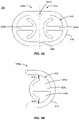
- FIGS. 7 A- 7 E illustrate additional embodiments of an insertable device.
- FIG. 8 illustrates a cross-sectional view of an additional embodiment of an extrusion for creating a tube of FIG. 3 .
- FIG. 1 A illustrates a system 100 for controlling uterine hemorrhaging, according to an embodiment.
- the system 100 functions to reduce or entirely stop uterine hemorrhaging, which may occur after childbirth when a woman experiences uterine atony, wherein the uterus fails to contract. Controlling uterine hemorrhaging substantially reduces the total blood lost from the uterus and may reduce a woman's need for a blood transfusion or a hysterectomy.
- the system 100 facilitates contraction of the uterus by sealing an opening to the uterus and providing a pressure change within the uterus.
- the system 100 includes an insertable device 105 , a pump 110 , and a collection container 115 .
- the insertable device 105 is configured to be inserted into the uterus to transmit the pressure change provided by the pump 110 .
- the insertable device 105 is delivered transvaginally (through the vagina) such that a distal portion 120 of the insertable device 105 is positioned within the uterus while a proximal portion 125 of the insertable device 105 remains external to the uterus.
- the distal portion 120 may have a flexible structure such that it conforms to the anatomy of the uterus and allows the distal portion 120 to create a seal at the opening of the uterus.
- the proximal portion 125 of the insertable device 105 couples to the pump 110 .
- the distal and proximal portions 120 , 125 may have one or more channels and/or openings that allow fluid communication (e.g., of air, biological materials, etc.) between the uterus, the pump 110 , and the collection container 115 .
- the one or more channels and/or openings transfer the vacuum between the uterus and the pump 110 .
- the insertable device 105 may have a sheath that facilitates insertion of the insertable device 105 into the uterus and may additionally prevent a premature connection of the airflow from the pump 110 to the uterus. The insertable device 105 will be discussed in further detail with regards to FIG. 2 .
- the pump 110 creates a pressure change that generates a vacuum within the uterus.
- the pump 110 is coupled to the proximal portion 125 of the insertable device 105 .
- a connection tubing 130 attaches to the proximal portion 125 at a first end and attaches to the pump 110 at a second end, thereby coupling the pump 110 and the insertable device 105 .
- the connection tubing 130 includes a directional control valve 135 that allows fluid to flow in one direction and prevents fluid from flowing in the opposite direction.
- the pump 110 When actuated, the pump 110 creates an airflow that is transmitted through the channels and/or openings of the insertable device 105 to the uterus.
- vacuum pumps are configured to remove molecules from a sealed volume in order to leave behind a partial vacuum. Since the uterus is sealed by the distal portion 120 of the insertable device 105 , the airflow by the pump 110 decreases the pressure inside the uterus, causing the uterine pressure to drop lower than the atmospheric pressure outside of the uterus and resulting in a negative pressure. The negative pressure ensures that the airflow travels in a single direction from the uterus and through the insertable device 105 towards the pump 110 .
- the negative pressure generates a vacuum inside the uterus, which facilitates tamponade, arterial vessel constriction, and contractile movement of the uterine wall by providing a uniform mechanical stimulus.
- generating a vacuum allows biological materials within the uterus to be removed.
- Biological materials may include blood, tissue, etc.
- the pump 110 may be power/automatically operated or manually operated. The embodiments in which the pump 110 is manually operated, the pump 110 may create a negative pressure within the uterus when in a first state, and in a second state, the pump 110 may draw biological materials into the collection container 115 while maintain the negative pressure within the uterus. While a “negative pressure” is referred to throughout, some embodiments may generate a positive pressure inside the uterus to facilitate contractions of the uterus.
- the collection container 115 collects the biological materials removed from the uterus.
- the collection container 115 is coupled to the proximal portion 125 of the insertable device 105 .
- the collection container 115 may be coupled via a connection tubing 140 that is integrated into the proximal portion 125 .
- the pump 110 When the pump 110 is actuated, the biological materials travel from the uterus, into the openings and/or channels of the insertable device 105 , and through the connecting tubing 140 into the collection container 115 . Collecting biological materials from the uterus may allow a user to monitor and measure the amount of blood loss due to uterine hemorrhaging.
- the collection container 115 may be configured as an inline filter that is positioned before the connection tubing 130 to the pump 110 , allowing biological materials from the uterus to flow through the insertable device 105 and be filtered out before the pump 110 .
- the system 100 may be used to prevent postpartum hemorrhage in addition to monitoring and/or treating it.
- the system 100 may be used in any woman after birth to aid uterine contraction.
- the flexibility of the insertable device 105 allows a healthcare provider (e.g., nurse, physician, surgeon, etc.) to palpate a woman's uterine tissue abdominally in order to detect if and/or when the uterus has contracted.
- the flexibility of the insertable device 105 allows the insertable device 105 to be flexed and positioned while other vaginal wall or tissue repair surgical procedures are being conducted.
- the insertable device 105 may be configured for insertion into a vaginal canal or a cervical canal such that the insertable device 105 remains external to the uterus.
- the distal portion 120 creates a seal between a vaginal opening or a cervical opening and the uterus. Creating the seal allows the airflow by the pump 110 to decrease the pressure inside the uterus, causing the uterine pressure to drop lower than the atmospheric pressure outside of the uterus and generating a vacuum inside the uterus. As previously described, this facilitates tamponade, arterial vessel constriction, and contractile movement of the uterine wall by providing a uniform mechanical stimulus.
- This configuration of the insertable device 105 may provide a less invasive method for controlling uterine hemorrhaging.
- FIG. 1 B illustrates a system 100 for controlling uterine hemorrhaging, according to an additional embodiment.
- the system 100 includes an insertable device 105 , a pump 110 , and a collection container 115 .
- the collection container 115 is connected in-line with the pump 110 .
- the proximal portion 125 of the insertable device 105 couples to the collection container 115 and the pump 110 via the connection tubing 130 .
- the fluid e.g., air, biological materials, etc.
- the biological material is removed from the connection tubing 130 prior to reaching the pump 110 and collects in the collection container 115 .
- FIG. 1 C illustrates a system 100 for controlling uterine hemorrhaging, according to an additional embodiment.
- the system 100 includes an insertable device 105 and a pump 110 .
- the proximal portion 125 of the insertable device 105 couples to the pump 110 via the connection tubing 130 .
- the collection container 115 is integrated with the pump 110 such that the fluid (e.g., air, biological materials, etc.) flows through the connection tubing 130 into the pump 110 , in which the biological materials are collected into a separate compartment of the pump 110 .
- the compartment that collects the biological material may be removable from the pump 110 . This may assist a healthcare provider in monitoring the amount of biological material collected.
- FIG. 2 illustrates the insertable device 105 , according to an embodiment.
- the insertable device 105 is configured to be inserted into the uterus to transmit the pressure change provided by the pump 110 .
- the distal portion 120 is inserted into the uterus and seal an opening to the uterus, and the proximal portion couples to the pump 110 .
- the insertable device 105 includes a tube connector 205 , a tube 210 , a bridge 215 , and a seal 220 .
- the tube 210 includes a connecting portion 225 and a suction portion 230 .
- Each component of the insertable device 105 may have a variety of designs and may be interchangeable to create alternate configurations of the insertable device 105 .
- the tube connector 205 couples the insertable device 105 to the pump 110 .
- the tube connector 205 couples to the pump 110 via connection tubing (e.g., connecting tubing 130 ).
- connection tubing e.g., connecting tubing 130
- the tube connector 205 is tapered such that it may be inserted into the connection tubing and secured to the connection tubing via an interference it (e.g., press fit or friction fit).
- the tube connector 205 attaches to a proximal end of the connecting portion 225 of the tube 210 .
- the tube connector 205 may be attached to the connecting portion 225 via an interference fit (e.g., press fit or friction fit), an adhesive, a threaded interface, or any other suitable securing mechanism.
- the tube connector 205 may be composed of rigid or semi-rigid plastic (e.g., polyethylene, polypropylene) or any other suitable material.
- the tube 210 acts as a conduit for air and biological materials.
- the tube 210 may comprise one or more channels that couple airflow from the pump 110 to the uterus to transmit a change in pressure inside the uterus.
- the tube 210 includes a single channel having surface features on an internal surface of the channel. Alternate embodiments of the tube 210 will be discussed in further detail with regards to FIGS. 7 B- 7 E .
- the internal surface features protrude from the internal surface of the channel and may aid the flow of air and biological materials through the tube 210 .
- the internal surface features may have a variety of configurations, which will be discussed in further detail with regards to FIGS. 4 - 5 .
- the tube 210 includes the connecting portion 225 and the suction portion 230 .
- the connecting portion 225 transmits airflow from the pump 110 to the suction portion 230 of the tube 210 .
- the tube connector 205 is attached at a proximal end of the connecting portion 225 and removably secures the connecting portion 225 to the pump 110 .
- the channel of the tube 210 extends down the length of the connecting portion 225 .
- the tube 210 branches out to form the suction portion 230 .
- the connecting portion 225 and the suction portion 230 are integrally formed of the same piece of material (i.e., have a unitary construction).
- the tube's 210 single piece of material is at least partially physically split in half, thereby creating two branches 235 a , 235 b of the suction portion 230 and exposing the channel of the tube 210 on a medial side of each branch 235 . Exposing the channel of the tube 210 connects the airflow between the pump 110 and the uterus, allowing the tube 210 to transmit the change in pressure provided by the pump 110 to the uterus.
- the exposed channels are beneficially located along a medial side of each branch 235 of the suction portion 230 such that the exposed channels are oriented away from an interior wall of the uterus when the insertable device 105 is inserted. This configuration prevents uterine tissue or other tissue from obstructing the exposed channels and preventing airflow when the pump 110 is actuated.
- the orientation of the exposed channels on the suction portion 230 may vary.
- the exposed channels may be oriented at an off-axis angle from the medial surface of the suction portion 230 .
- the exposed channels may be oriented at an angle relative to an axis (e.g., a bisecting axis) of the medial surface.
- the exposed channels may be located on a surface other than the medial surface of the suction portion 230 (e.g., a lateral surface of the suction portion 230 ). In these embodiments, channels may not be exposed after the tube 210 is split to create the two branches 235 a , 235 b . In other embodiments, the exposed channels on the suction portion 230 may be some combination thereof. In addition, some exposed channels may not be configured to pass biological material from the uterus. In some embodiments, the connecting portion 225 and the suction portion 230 may be separate components/pieces of material that are coupled to each other.
- the bridge 215 spans between the branches 235 of the suction portion 230 . Each end of the bridge 215 is attached to a distal end of a branch 235 of the suction portion 230 .
- the bridge 215 may be attached via an interference fit (e.g., friction fit or press fit), an adhesive, a threaded interface, or some combination thereof.
- the length of the bridge 215 is sufficient enough to maintain a separation between the branches 235 of the suction portion 230 .
- the manner in which the branches 235 are constructed, for example as described with respect to FIG.
- the branches 235 have a natural tendency to come together in a resting state (i.e., when no external force is exerted on the branches 235 ). However, this tendency may cause the exposed channels on each branch 235 to become obstructed in the resting state. Thus, the bridge 215 exerts a force on each branch 235 to separate the branches 235 into a split state. This configuration prevents the branches 235 of the suction portion 230 from collapsing into each other when the pump 110 is actuated and thereby obstructing the airflow between the pump 110 and the uterus.
- the bridge 215 maintains the alignment of the branches 235 of the suction portion 230 such that the exposed channels along the medial side of the suction portion 230 remain facing inward towards each other. In one embodiment this is accomplished by forming the bridge 215 , which has a substantially curved body with rounded edges, directionally-limiting so that the insertable device 105 is positioned comfortably within the uterus when inserted and to prevent damage to the uterine wall, while also maintaining its orientation when inserted so as to keep the exposed channel oriented inward as discussed.
- the shape of the bridge 215 may vary in terms of the length, width, curvature, thickness, etc.
- the configuration of the distal portion 120 may vary, for example, to form a circular, elliptical, triangular, or horn-shaped loop, or any other suitable geometries for placement within the uterus.
- Alternate embodiments of the bridge 215 will be discussed with regards to FIG. 7 E .
- the insertable device 105 may not include a bridge 215 .
- the seal 220 creates a seal at the opening of the uterus.
- the seal 220 is a disk positioned at a distal end of the connecting portion 225 , adjacent to the suction portion 230 , however in alternate embodiments it may be placed at varying locations along the connecting portion 225 depending on the size/length of the other elements.
- the disk may be circular, elliptical, or any other suitable geometry for sealing an opening to the uterus.
- the disk may or may not include a lip around its perimeter, wherein the lip may help position the seal against the uterine wall.
- the disk may have a convex or a concave profile.
- the seal 220 may be composed of semi-flexible plastics, such as silicone, polyethylene, polypropylene, or any other suitable medical-grade material.
- the flexible material of the seal 220 allows the seal 220 to conform to the anatomy of the uterus such that the seal 220 may be positioned against an opening of the uterus to form a seal between the uterus and an environment external to the uterus. Sealing the uterus allows the insertable device 105 to create a vacuum and maintain a negative pressure within the uterus to facilitate contraction of the uterus.
- the seal 220 may be configured to form a seal at any point from the vulva, the cervix, the vaginal canal, or within the uterus.
- Additional embodiments of the seal 220 include a plurality of disks, a cup, a balloon, and a sleeve, which may be interchangeable with other components of the insertable device 105 , for example as described with respect to any of the exemplary embodiments herein. These additional embodiments will each be discussed in further detail with regards to FIGS. 7 A- 7 E .
- the insertable device 105 may include a sheath (not shown) that facilitates insertion of the insertable device 105 into the uterus and may additionally prevent a premature connection of the airflow from the pump 110 to the uterus.
- the sheath may cover a portion of the tube 210 , the bridge 215 , and/or the seal 220 , or some combination thereof.
- the sheath may be in the form of a translatable outer tube that encloses a portion of the tube 210 , a removable membrane that encloses distal portions of the insertable device 105 , or other structures having a similar configuration. The sheath may be removed once the suction portion 230 is positioned within the uterus.
- Removal of the sheath may simultaneously release or position the seal 220 in the uterus to create the seal.
- the sheath may be re-installed onto the insertable device 105 .
- the re-installation process may simultaneously break the seal from the seal 200 and cut off the connection of the airflow between the pump 110 and the uterus.
- FIG. 3 illustrates the tube 210 of the insertable device of FIG. 2 , according to an embodiment.
- the tube 210 is manufactured through an extrusion process, though in other embodiments the tube 210 may be manufactured in other ways.
- An extrusion process is used to create objects having a desired cross-sectional profile by pushing a material through a die of the desired cross-section. Materials such as silicone, polyethylene, polypropylene, or any other suitable medical-grade material may be used for the extrusion process of the tube 210 . Once the extrusion is created, the extrusion may be cut to a desired length.
- the tube 210 is extruded using a semi-flexible material, which allows the insertable device to conform to the anatomy of a uterus when inserted.
- the extrusion undergoes post-processing to form the final product, the tube 210 .
- the tube 210 includes the connecting portion 225 and the suction portion 230 .
- a portion of the extrusion is at least partially split in half along its length.
- the extrusion is cut from a distal end of the tube 210 down to the length of the extrusion by a distance d.
- the distance d is a suitable length that allows the suction portion 230 to be inserted comfortably into a uterus.
- the die may be designed such that the extrusion includes a groove on an internal or external surface that extends down a certain length of the extrusion.
- the groove may facilitate the cutting process by indicating the location of the cut and acting as a guide for the tool performing the cut.
- the groove indicates a location at which the wall thickness of the extrusion is thinner than the remainder of the extrusion. A thinner wall thickness may ease the cutting process or allow two halves of the extrusion to be separated manually to form the suction portion 230 .
- the tube 210 is manufactured through a GeoTrans® extrusion process.
- the die may be designed such that the desired cross-section of the extrusion changes along the length of the extrusion.
- a desired cross-section for the connecting portion 225 may differ from a desired cross-section for the suction portion 230 .
- the cross-section of the connecting portion 225 may be substantially cylindrical or elliptical while the cross-section of the suction portion 230 may include one or more channels.
- the cross-section of the extrusion may change along its length in an alternating pattern. The change in cross-section between the connecting portion 225 and the suction portion 230 may be designed to occur transitionally or abruptly.
- the die may be designed such that the cross-section of the tube 210 includes surface features on an internal surface of the tube 210 .
- Example surface features are illustrated in FIG. 3 , wherein each branch 235 of the suction portion 230 includes a middle protrusion that extends down the length of the internal surface of the tube 210 .
- the surface features may aid the flow of air and biological materials within the tube 210 , which will be discussed in further detail with regards to FIGS. 4 - 5 .
- the design of the insertable device 105 specifically the split state of the branches 235 and the bridge 215 that maintains separation of the branches 235 , provides greater design flexibility for the surface features on the channel as the branches 235 are not required to bend or curve substantially.
- FIG. 4 A illustrates a cross-sectional view of an extrusion 400 for creating the tube 210 , according to an embodiment. Specifically, a cross-section of the suction portion 230 of the tube 210 is shown before two halves 405 a , 405 b of the extrusion 400 are split to create the separate branches of the suction portion 230 .
- the extrusion 400 includes an outer wall 410 and a channel 415 .
- the outer wall 410 forms the external boundary of the tube 210 .
- the outer wall 410 surrounds the channel 415 , through which air and biological materials can pass. As illustrated in FIG. 4 A , the outer wall 410 is substantially of uniform thickness.
- the thickness of the outer wall 410 may be between approximately 1 to 2.5 millimeters (mm).
- the outer wall 410 includes two grooves 420 a , 420 b that are located on opposite edges of the outer wall.
- the grooves 420 a , 420 b are located on an internal and external surface of the outer wall 410 , such that the thickness of the outer wall 410 narrows at the grooves 420 a , 420 b .
- the grooves 420 a , 420 b facilitate the separation of the two halves 405 a , 405 b to form the separate branches of the suction portion 230 of the tube 210 .
- FIG. 1 The outer wall 410 includes two grooves 420 a , 420 b that are located on opposite edges of the outer wall.
- the grooves 420 a , 420 b are located on an internal and external surface of the outer wall 410 , such that the thickness of the outer wall 410 narrows at the grooves 420 a ,
- the grooves 420 a , 420 b extend down the length of the tube 210 for the suction portion 230 .
- the connecting portion 225 may not include the grooves 420 a , 420 b and only the suction portion 230 includes the grooves 420 a , 420 b . This configuration may prevent propagating the separation of the two halves 405 a , 405 b into the connecting portion 225 .
- the cross-sectional view shown in FIG. 4 A also illustrates the cross-section of the connecting portion 225 .
- the surface of the channel 415 includes the following surface features: protrusions 425 a , 425 b and protrusions 430 a , 430 b , 430 c , 430 d .
- the surface features are arranged such that the cross-section of the extrusion 400 is substantially symmetrical. This configuration ensures that each branch of the suction portion 230 includes the same surface features once the extrusion 400 is split along the grooves 420 a , 420 b .
- the protrusions 425 a , 425 b are positioned at a middle portion of the channel 415 and protrude into the center of the channel 415 towards each other.
- protrusions 430 a , 430 b are positioned to the right of grooves 420 a , 420 b , respectively, and protrude towards each other, while protrusions 430 c , 430 d , are positioned to the left of grooves 420 b , 420 a , respectively, and protrude towards each other.
- This configuration of protrusions 425 , 430 divides the channel 415 into smaller channels, which provides each branch of the suction portion 230 with certain properties, discussed in further detail with regards to FIG. 4 B .
- FIG. 4 B illustrates a cross-sectional view of a branch 435 a of the suction portion 230 , according to an embodiment.
- the cross-section shown is of the half 405 a after the two halves 405 a , 405 b of the extrusion 400 are split to create separate branches of the suction portion 230 .
- the half 405 a forms the branch 435 a .
- branch 435 b is not shown, it is formed by the half 405 b .
- the protrusions 425 a , 430 a , 430 b divide the channel 415 into two smaller channels 440 a , 440 b , wherein each channel has a respective opening 445 a , 445 b .
- openings in the suction portion 230 allow fluid communication between the uterus and the pump 110 . Dividing the channel 415 into smaller channels 440 a , 440 b distributes the airflow from the pump 110 and increases the number of pathways by which air and biological materials can travel. Thus, if a single pathway becomes obstructed by biological materials, other pathways remain accessible, and the system 100 can effectively maintain a negative pressure inside the uterus.
- the openings 445 a , 445 b are located on a medial side of the respective branches 435 such that when the suction portion 230 is inserted into the uterus, the outer wall 410 faces the uterine wall and the openings 445 a , 445 b .
- This configuration prevents uterine tissue or other tissue from obstructing the openings 445 a , 445 b and preventing airflow when the pump 110 is actuated.
- the openings 445 a , 445 b are configured to allow biological materials of a certain size through the openings 445 a , 445 b and into the channels 440 a , 440 b such that these biological materials may be removed from the uterus and collected in the collection container 115 .
- the size of each opening 445 a , 445 b is between approximately 1 to 4 millimeters (mm). In some embodiments, the size of each opening 445 a , 445 b is between 2 to 3.5 millimeters (mm). Openings of this size may additionally be configured to break up masses of biological material that have formed a clot. By breaking up the masses, the openings 445 a , 445 b are able to prevent obstruction of the airflow from the pump 110 and allow the biological material to be collected in the collection container 115 .
- FIG. 5 A illustrates a cross-sectional view of an additional embodiment of an extrusion 500 for creating the tube 210 .
- a cross-section of the suction portion 230 of the tube 210 is shown before two halves 505 a , 505 b of the extrusion 500 are split to create the separate branches of the suction portion 230 .
- the extrusion 500 includes an outer wall 510 and a channel 515 .
- the outer wall 510 forms the external boundary of the tube 210 .
- the outer wall 510 surrounds the channel 515 , through which air and biological materials can pass. As illustrated in FIG. 5 A , the outer wall 510 is substantially of uniform thickness.
- the thickness of the outer wall 510 may be between approximately 1 to 2.5 millimeters (mm).
- the outer wall 510 includes two grooves 520 a , 520 b that are located on opposite edges of the outer wall. Similar to grooves 420 a , 420 b , the grooves 520 a , 520 b facilitate the separation of the two halves 505 a , 505 b to form the separate branches of the suction portion 230 of the tube 210 . In the embodiment of FIG.
- the grooves 520 a , 520 b are located only on an internal surface of the outer wall 510 , but, in some embodiments, the grooves 520 a , 520 b may be located on both an internal and external surface of the outer wall 510 .
- the surface of the channel 515 includes the following surface features: protrusions 525 a , 525 b .
- the protrusions 525 a , 525 b are arranged such that the cross-section of the extrusion 500 is substantially symmetrical. This configuration ensures that each branch of the suction portion 230 includes the same surface features once the extrusion 500 is split along the grooves 520 a , 520 b .
- the protrusions 525 a , 525 b are positioned at a middle portion of the channel 515 and protrude into the center of the channel 515 towards each other. In the embodiment of FIG.
- each protrusion 525 a , 525 b has a distal end that extends in a different direction to the portion of the protrusion that extends from the outer wall.
- this different direction of extension forms a shape similar to an umbrella, wherein each protrusion 525 includes a middle support structure with a curved arm extending from each side of the support structure.
- other shapes may be formed, such as T-shaped protrusions, and so on. Regardless of the exact shape, this general configuration of protrusions 525 a , 525 b divides the channel 515 into smaller channels, which provides each branch of the suction portion 230 with certain properties, discussed in further detail with regards to FIG. 5 B
- FIG. 5 B illustrates a cross-sectional view of a branch 535 a of the suction portion 230 .
- the cross-section shown is of the half 505 a after the two halves 505 a , 505 b of the extrusion 500 are split to create separate branches of the suction portion 230 .
- the half 505 a forms the branch 535 a .
- branch 535 b is not shown, it is formed by the half 505 b .
- the protrusion 525 a divides the channel 515 into two smaller channels 540 a , 540 b wherein each channel has a respective opening 545 a , 545 b . Similar to the embodiment of FIG.
- the openings 545 a , 545 b are distanced apart from each other due to the configuration of the protrusion 525 a . Separating the openings 545 a , 545 b by a distance may decrease the likelihood of the openings 545 a , 545 b becoming obstructed by biological materials at the same time, potentially by the same mass of biological material.
- the openings 545 a , 545 b are located on a medial side of the respective branches 535 such that when the suction portion 230 is inserted into the uterus, the outer wall 510 faces the uterine wall and the openings 545 a , 545 b .
- This configuration prevents uterine tissue or other tissue from obstructing the openings 545 a , 545 b and preventing airflow when the pump 110 is actuated.
- the openings 545 a , 545 b are configured to allow biological materials of a certain size through the openings 545 a , 545 b and into the channels 540 a , 540 b such that these biological materials may be removed from the uterus and, in some embodiments, collected in the collection container 115 .
- the size of each opening 545 a , 545 b is between approximately 1 to 4 millimeters (mm). Openings of this size may additionally be configured to break up a mass of biological material (e.g., a clot or clump of tissue). By breaking up the mass, the openings 545 a , 545 b are able to prevent obstruction of the airflow from the pump 110 and allow the biological material to be collected in the collection container 115 .
- FIG. 6 A illustrates a method for attaching the bridge 215 to the tube 210 , according to an embodiment.
- a first end of the bridge 215 is attached to a distal end of branch 235 a of the suction portion 230
- a second end of the bridge 215 is attached to a distal end of branch 235 b of the suction portion 230 .
- This configuration of the suction portion of the tube 210 ensures that the branches 235 are separated and remain in a split state when inserted into the uterus.
- each end of the bridge 215 includes a mating protrusion 605 a ( 605 b not shown) that extends from an end of the bridge 215 .
- the mating protrusions 605 a , 605 b are inserted into a channel of the branches 235 b , 235 a , respectively.
- the mating protrusions 605 a , 605 b may be inserted with an interference fit (e.g., friction fit or press fit), an adhesive, a threaded interface, or some combination thereof.
- the mating protrusions 605 a , 605 b are silicone bonded to the respective branches 235 b , 235 a.
- FIG. 6 B illustrates mating protrusion 605 a that secures a first end of the bridge 215 to the branch 235 a , according to an embodiment.
- the mating protrusion 605 a may include a cavity 610 that complements surface features located on a channel of the branch 235 a .
- the shape of the cavity 610 is designed to complement the shape of the surface features described with regards to FIG. 5 B .
- the surface feature 525 a may be inserted into the cavity 610 , which may improve the stability and security of the attachment between the bridge 215 and the branch 235 a .
- the cavity 610 provides a greater surface area for silicone bonding the mating protrusions 605 a , 605 b to the respective branches 235 b , 235 a .
- Other embodiments may have a cavity 610 designed to complement the shape of the surface features illustrated in FIGS. 4 A and 4 B or any other channel surface feature configuration.
- the bridge 215 may be configured to transmit the airflow from the tube 210 .
- the bridge 215 may include channels or holes along a medial side of the bridge 215 , and the mounting protrusions 605 a , 605 b may include channels that couple the airflow of the suction portion 230 to the bridge 215 . This configuration provides additional pathways by which the airflow and/or biological materials can travel.
- FIGS. 7 A- 7 E illustrate additional embodiments of an insertable device.
- an insertable device includes several components, such as a tube connector, a tube having a connecting portion and a suction portion, a bridge, and a seal.
- Each component may have a variety of designs, which will be discussed in further detail.
- different designs of the components may be interchangeable and combined in several ways to create different configurations of an insertable device.
- FIG. 7 A illustrates an insertable device 700 , according to an embodiment.
- the insertable device 700 includes the tube connector 205 , the tube 210 having the connecting portion 225 and the suction portion 230 , the bridge 215 , and a seal 705 .
- the seal 705 creates a seal at the opening of the uterus.
- the seal 705 is composed of three disks 710 a , 710 b , 710 c positioned at a distal end of the connecting portion 225 , adjacent to the suction portion 230 .
- Each disk 710 may be composed of a semi-flexible material, such as silicone, polyethylene, polypropylene, or any other suitable medical-grade material, allowing each disk 710 to conform to the anatomy of the uterus.
- the diameter of each disk 710 incrementally decreases such that the largest disk 710 c is closest to the suction portion 230 and the smallest disk 710 a is farthest away from the suction portion 230 .
- the decreasing diameters of the disks 710 may improve the ability of the seal 705 to be positioned against an opening of the uterus such that each disk 710 may abut the uterine wall to form a seal between the uterus and an environment external to the uterus.
- Having a seal including three disks 710 may improve the quality of the seal formed and provide redundancy in maintaining the seal.
- Other embodiments may include a varying number of disks that may be positioned at different distances relative to each other (e.g., two disks that are spaced farther apart or ten disks that are spaced closer together).
- FIG. 7 B illustrates an insertable device 715 , according to an embodiment.
- the insertable device 700 includes the tube connector 205 , a tube 720 having a connecting portion 725 and a suction portion 730 , and a seal 735 .
- the tube 720 acts as a conduit for air and biological materials.
- the tube 720 may comprise one or more channels that couple airflow from the pump 110 to the uterus to transmit a change in pressure inside the uterus.
- the tube 720 is a flexible tube that is folded to form the connecting portion 725 and the suction portion 730 .
- the sections of the tube 720 forming the connecting portion 725 may be adjoined via an adhesive, one or more over-molded components secured around the tube 720 , or a heat shrink wrap placed over the tube 720 . Meanwhile, the suction portion 730 remains a loop.
- the construction of the tube 720 ensures that the alignment of the openings and/or channels on the medial side of the loop of the suction portion 730 remain facing away from the uterine wall upon insertion.
- this configuration eliminates the need for a connecting element (e.g., bridge 215 ) between branches of the tube, which may decrease the cost of manufacturing the tube 720 .
- the rigidity of the tube 720 needs to be appropriately determined such that the tube 720 may be flexible enough to form the loop of the suction portion 730 yet rigid enough to prevent the suction portion 730 from potentially deforming and obstructing the openings and/or channels on the medial side of the loop.
- the design of the surface features on a surface of the channel of the tube 720 may be limited due to the desired curvature of the tube 720 .
- the suction portion 730 includes one or more openings 738 located along a medial side of the loop such that the openings 738 are oriented away from an interior wall of the uterus when the insertable device 105 is inserted.
- This configuration prevents uterine tissue or other tissue from obstructing the openings 738 and preventing airflow when the pump 110 is actuated.
- the openings 738 may be circular, elliptical, polygonal, or any other suitable shape that allows air and biological materials to travel through.
- the openings 738 may be channels that extend along the medial side of the loop.
- the seal 735 creates a seal at an opening of the uterus.
- the seal 735 is positioned at a distal end of the connecting portion 225 , adjacent to the suction portion 730 .
- the seal 735 is shaped similar to a cup, wherein a bottom portion of the cup shape is configured to abut the uterine wall at an opening of the uterus upon insert of the insertable device 730 into the uterus.
- the seal 735 is composed of a semi-flexible material, such as silicone, polyethylene, polypropylene, or any other suitable medical-grade material, that allow the seal 735 to conform to the anatomy of the uterine wall.
- FIG. 7 C illustrates an insertable device 740 , according to an embodiment.
- the insertable device 740 includes the tube connector 205 , the tube 720 having the connecting portion 725 and the suction portion 730 , and the seal 220 .
- the insertable device 740 combines the tube configuration described with regards to FIG. 7 B with the seal configuration described with regards to FIG. 2 .
- FIG. 7 D illustrates an insertable device 745 , according to an embodiment.
- the insertable device 745 is an embodiment of insertable device 740 .
- the insertable device 745 includes the tube connector 205 , the tube 720 having the connecting portion 725 and the suction portion 730 , the seal 220 , and a shield 750 .
- the shield 750 is a porous mesh that allows particles of a certain size to pass through the mesh.
- the shield 750 encloses the suction portion 730 to prevent uterine tissue from obstructing the openings 738 while allowing other biological materials (e.g., blood) to pass through.
- the shield 750 may be composed of gauze, nylon, or other suitable materials that may be placed within the uterus.
- FIG. 7 E illustrates an insertable device 755 , according to an embodiment.
- the insertable device 755 includes the tube connector 205 , a tube 760 having a connecting portion 765 and a suction portion 770 , and a seal 775 .
- the tube 760 acts as a conduit for air and biological materials. While the tube 760 is similar in geometry to tube 720 , the tube 760 is made of two individual tubes 780 a , 780 b rather than a single folded tube. Each tube 780 a , 780 b includes an internal channel extending down the length of the tube. In the embodiment of FIG. 7 E , tubes 780 a , 780 b are positioned adjacent to each other such that a portion of the tubes 780 a , 780 b can be adjoined to form the connecting portion 765 . The tubes may be adjoined via an adhesive, one or more over-molded components secured around the connecting portion 765 , or a heat shrink wrap placed over the tube connecting portion 765 .
- the remaining portions of the tubes 780 a , 780 b are curved to mate an end of tube 780 a to an end of tube 780 b , forming a loop to create the suction portion 770 .
- the ends of the tubes 780 a , 780 b may be coupled together using a plug 785 .
- a first end of the plug 785 is inserted into a channel of tube 780 a
- a second end of the plug 785 is inserted into a channel of tube 780 b .
- the plug 785 may be secured within the tubes 780 a , 780 b using an adhesive.
- the plug 785 may include openings or channels to form a continuous pathway for airflow and/or biological materials through the tube 760 .
- the plug 785 may be designed to fit over the ends of the tubes 780 a , 780 b as a cross tube connector.
- the connecting element (such as bridge 215 or plug 785 ) can have a variety of configurations and be of any size, depending upon the rigidity of the tube and given that the connecting element appropriately mates the branches such that the openings or channels on each branch remain unobstructed and allow a vacuum to be created within the uterus upon insertion of the insertable device.
- the suction portion 770 includes one or more openings 790 .
- the openings 790 are created by skiving the external surface of the suction portion 770 .
- a skiving process carves out notches in the surface of the suction portion 770 .
- the openings 790 are located along a medial side of the loop such that the openings 790 are oriented away from an interior wall of the uterus when the insertable device 105 is inserted. This configuration prevents uterine tissue or other tissue from obstructing the openings 790 and preventing airflow when the pump 110 is actuated.
- the seal 775 creates a seal at an opening of the uterus.
- the seal 775 is a sleeve or a balloon that can be inflated once the suction portion 770 is positioned within the uterus.
- the seal 775 may be inserted while flattened, allowing the seal 775 to be properly positioned before the seal 775 is inflated.
- the seal 775 may be positioned within the vaginal canal, cervix, or uterus.
- the seal 775 includes a tube 795 that may connect to the pump 110 to inflate the seal 775 .
- the seal 775 may be composed of silicone, polyethylene, polypropylene, or any other suitable medical-grade material.
- FIG. 8 illustrates a cross-sectional view of an additional embodiment of an extrusion 800 for creating the tube 210 .
- a cross-section of the suction portion 230 of the tube 210 is shown before two halves 805 a , 805 b of the extrusion 800 are split to create the separate branches of the suction portion 230 .
- the extrusion 800 includes an outer wall 810 , channel 815 , channels 820 a , 820 b , and rings 825 a , 825 b .
- the outer wall 810 forms the external boundary of the tube 210 .
- the outer wall 810 encloses the channels 815 , 820 a , 820 b . As illustrated in FIG.
- the outer wall 810 is substantially of uniform thickness.
- the thickness of the outer wall 810 may be between approximately 1 to 2.5 millimeters (mm).
- the outer wall 810 includes two grooves 830 a , 830 b that are located on opposite edges of the outer wall 810 .
- the grooves 830 a , 830 b are located on an internal and external surface of the outer wall 810 , such that the thickness of the outer wall 810 narrows at the grooves 830 a , 830 b .
- the grooves 830 a , 830 b facilitate the separation of the two halves 805 a , 805 b to form the separate branches of the suction portion 770 of the tube 760 .
- the branches are curved towards each other to form a loop, wherein a first end of a first branch mates with a first end of a second branch.
- a pin may be inserted into the rings 825 a , 825 b . The pin may be adhered within the rings 825 a , 825 b.
- the channel 815 is exposed to allow fluid communication between the pump 110 to the uterus.
- the wall between the channel 815 and the respective channels 820 a , 820 b may include one or more openings (e.g., holes or channels) such that biological material may enter the channel 815 and flow through to the channels 820 a , 820 b .
- the channels 820 a , 820 b act as drain channels. This configuration may help the channel 815 remain unobstructed.
Abstract
Description
Claims (23)
Priority Applications (2)
| Application Number | Priority Date | Filing Date | Title |
|---|---|---|---|
| US15/683,561 US11517336B2 (en) | 2016-08-24 | 2017-08-22 | Uterine hemorrhage controlling system and method |
| US18/052,358 US20230093148A1 (en) | 2016-08-24 | 2022-11-03 | Uterine hemorrhage controlling system and method |
Applications Claiming Priority (2)
| Application Number | Priority Date | Filing Date | Title |
|---|---|---|---|
| US201662378889P | 2016-08-24 | 2016-08-24 | |
| US15/683,561 US11517336B2 (en) | 2016-08-24 | 2017-08-22 | Uterine hemorrhage controlling system and method |
Related Child Applications (1)
| Application Number | Title | Priority Date | Filing Date |
|---|---|---|---|
| US18/052,358 Continuation US20230093148A1 (en) | 2016-08-24 | 2022-11-03 | Uterine hemorrhage controlling system and method |
Publications (2)
| Publication Number | Publication Date |
|---|---|
| US20180055523A1 US20180055523A1 (en) | 2018-03-01 |
| US11517336B2 true US11517336B2 (en) | 2022-12-06 |
Family
ID=61241110
Family Applications (2)
| Application Number | Title | Priority Date | Filing Date |
|---|---|---|---|
| US15/683,561 Active 2039-02-21 US11517336B2 (en) | 2016-08-24 | 2017-08-22 | Uterine hemorrhage controlling system and method |
| US18/052,358 Pending US20230093148A1 (en) | 2016-08-24 | 2022-11-03 | Uterine hemorrhage controlling system and method |
Family Applications After (1)
| Application Number | Title | Priority Date | Filing Date |
|---|---|---|---|
| US18/052,358 Pending US20230093148A1 (en) | 2016-08-24 | 2022-11-03 | Uterine hemorrhage controlling system and method |
Country Status (11)
| Country | Link |
|---|---|
| US (2) | US11517336B2 (en) |
| EP (1) | EP3503789A4 (en) |
| JP (3) | JP7235657B2 (en) |
| KR (1) | KR102555360B1 (en) |
| CN (1) | CN110234261A (en) |
| AU (2) | AU2017316656B2 (en) |
| BR (1) | BR112019003632A8 (en) |
| CA (1) | CA3034778A1 (en) |
| MX (2) | MX2019002110A (en) |
| SG (1) | SG11201901451WA (en) |
| WO (1) | WO2018039250A1 (en) |
Cited By (3)
| Publication number | Priority date | Publication date | Assignee | Title |
|---|---|---|---|---|
| US20210338398A1 (en) * | 2020-05-04 | 2021-11-04 | Stoma Ventures, LLC | Disposable dental aerosol device |
| US11839408B2 (en) | 2022-04-06 | 2023-12-12 | Lucie Medical Inc. | Systems, devices, and methods for uterine hemostasis |
| US11849971B1 (en) * | 2022-11-28 | 2023-12-26 | Nemow Llc | Uterine toner device to prevent and control postpartum hemorrhage |
Families Citing this family (6)
| Publication number | Priority date | Publication date | Assignee | Title |
|---|---|---|---|---|
| US10064651B2 (en) | 2012-03-15 | 2018-09-04 | Inpress Technologies, Inc. | Uterine hemorrhage controlling system and method |
| EP3675944A1 (en) * | 2017-09-01 | 2020-07-08 | Cook Medical Technologies LLC | Postpartum hemorrhage balloon system |
| US20220022916A1 (en) * | 2018-12-10 | 2022-01-27 | Alydia Health, Inc. | Postpartum uterine hemorrhage device |
| RU199407U1 (en) * | 2019-04-06 | 2020-08-31 | Елена Александровна Горина | DEVICE FOR REMOVING THE TOP ENDOMETRY LAYER WITHOUT DAMAGE TO THE GROWTH LAYER |
| KR102451958B1 (en) * | 2020-12-22 | 2022-10-11 | 재단법인 오송첨단의료산업진흥재단 | Non-contact pressure measuring system for balloon catheter and method for measuring pressure using the same |
| US20230414254A1 (en) * | 2022-06-23 | 2023-12-28 | Boehringer Technologies, Lp | System and method for management of uterine hemorrhage |
Citations (139)
| Publication number | Priority date | Publication date | Assignee | Title |
|---|---|---|---|---|
| US1928992A (en) * | 1930-03-03 | 1933-10-03 | Clark Joseph George | Flexible tubing |
| US2185927A (en) | 1937-02-16 | 1940-01-02 | Herman A Shelanski | Insufflator |
| US2286462A (en) * | 1940-05-06 | 1942-06-16 | Rafe C Chaffin | Surgical suction drainage and irrigation tube |
| US2400251A (en) | 1943-07-29 | 1946-05-14 | Charles E Nagel | Gynecological instrument |
| US2483851A (en) * | 1946-09-19 | 1949-10-04 | Smith Charles Victor | Syringe |
| GB839965A (en) | 1956-01-14 | 1960-06-29 | Ockert Stephanus Heyns | Method and apparatus for facilitating the processes of parturition |
| US2981255A (en) | 1956-01-14 | 1961-04-25 | Ockert S Heyns | Method and apparatus for facilitating the processes of parturition |
| US3062215A (en) | 1956-01-14 | 1962-11-06 | Ockert S Heyns | Method and apparatus for facilitating the processes of parturition |
| US3517665A (en) | 1967-06-28 | 1970-06-30 | Sheldon Edward E | Negative pressure treatment device |
| US3626928A (en) | 1970-06-22 | 1971-12-14 | Becton Dickinson Co | Intrauterine washing apparatus |
| US3670732A (en) | 1970-05-11 | 1972-06-20 | Ralph R Robinson | Vacuum curette |
| US3774613A (en) | 1971-12-30 | 1973-11-27 | Scitron Corp | Suction curettage |
| US3828781A (en) | 1971-12-06 | 1974-08-13 | E Rothman | Method for withdrawing menstrual fluid |
| US3835843A (en) | 1971-06-28 | 1974-09-17 | H Karman | Medical instruments |
| US3848602A (en) * | 1972-04-19 | 1974-11-19 | Gutnick Morton | Abortion facilitating device and process |
| US3923051A (en) | 1974-03-18 | 1975-12-02 | Samuel Soichet | Inflatable intrauterine contraceptive device for postpartum use |
| US3929133A (en) | 1974-11-20 | 1975-12-30 | Int Pregnancy Advisory Service | Apparatus for removing, washing and displaying fragmentary products of operative procedures |
| US4013079A (en) | 1974-11-13 | 1977-03-22 | Lindemann Hans Joachim | Medical dilator |
| GB1469584A (en) | 1973-07-23 | 1977-04-06 | Bridgman H | Vacuum curette |
| US4111209A (en) | 1977-04-18 | 1978-09-05 | Datascope Corporation | Topical hypothermia apparatus and method for treating the human body and the like |
| US4141360A (en) | 1977-01-31 | 1979-02-27 | Lasswell Tull C | Menstrual extraction device |
| US4261697A (en) * | 1980-02-15 | 1981-04-14 | Newitter David A | Evacuating rubber dam frame |
| US4444548A (en) | 1980-08-08 | 1984-04-24 | University Testing Service Inc. | Suction apparatus |
| US4533345A (en) | 1983-06-14 | 1985-08-06 | Fertility & Genetics Associates | Uterine catheter |
| US4552557A (en) | 1983-10-21 | 1985-11-12 | Avvari Rangaswamy | Inflatable uterine hemostat |
| US4563183A (en) | 1983-04-06 | 1986-01-07 | Barrodale Patricia M | Female external catheter |
| US4681123A (en) | 1986-10-31 | 1987-07-21 | Valtchev Konstantin L | Chorion biopsy instrument |
| US4767404A (en) * | 1986-07-14 | 1988-08-30 | R & S Associates Co. | Surgical suction device having a perforated sleeve |
| SU1431746A1 (en) | 1985-08-07 | 1988-10-23 | Ворошиловградский Медицинский Институт | Arrangement for stopping postpartum hemorrhages |
| US4784654A (en) | 1982-11-16 | 1988-11-15 | Illinois Tool Works, Inc. | Urinary collection system and improved female urinary appliance |
| US4807625A (en) | 1987-07-07 | 1989-02-28 | Singleton Rosa R | Membrane puncturing aspirator with drainage shield |
| US4925452A (en) | 1988-03-08 | 1990-05-15 | Uresil Corporation | Multiple conduit drainage device |
| US4955875A (en) | 1987-09-11 | 1990-09-11 | Knowles Charlene G | Catamenial appliance |
| US4981477A (en) | 1988-04-16 | 1991-01-01 | Rudolf Schon | Catheter for introduction into the trachea and the bronchial system |
| US5030202A (en) | 1989-05-12 | 1991-07-09 | Equibov Ltd. | Lavage system |
| CN2097618U (en) | 1991-05-14 | 1992-03-04 | 张景权 | Multi-hole pipe for induced abortion |
| US5100395A (en) | 1989-10-06 | 1992-03-31 | Lior Rosenberg | Fluid drain for wounds |
| US5104377A (en) | 1989-08-10 | 1992-04-14 | C. R. Bard, Inc. | Uterine access device with automatic cervical adjustment |
| CN2116469U (en) | 1992-03-18 | 1992-09-23 | 陈孝路 | Two-purpose tube with sucking and abrading for induced abortion |
| US5160325A (en) * | 1986-10-06 | 1992-11-03 | C. R. Bard, Inc. | Catheter with novel lumens shapes |
| US5242438A (en) | 1991-04-22 | 1993-09-07 | Trimedyne, Inc. | Method and apparatus for treating a body site with laterally directed laser radiation |
| US5254084A (en) * | 1993-03-26 | 1993-10-19 | Geary Gregory L | Peritoneal catheter device for dialysis |
| CN2149183Y (en) | 1992-10-27 | 1993-12-15 | 王知难 | Half-hole type uterus sucker |
| US5360414A (en) | 1992-10-08 | 1994-11-01 | Yarger Richard J | Tube for draining body cavities, viscera and wounds |
| US5431173A (en) | 1991-05-29 | 1995-07-11 | Origin Medsystems, Inc. | Method and apparatus for body structure manipulation and dissection |
| US5451208A (en) | 1991-05-03 | 1995-09-19 | Goldrath; Milton H. | Endometrium coagulating apparatus and surgical method for thermal destruction of the endometrium |
| US5464409A (en) | 1993-12-09 | 1995-11-07 | Mohajer; Reza S. | Uterine manipulator and protector |
| US5472435A (en) | 1993-05-21 | 1995-12-05 | Navarre Biomedical, Ltd. | Drainage catheter |
| US5569284A (en) | 1994-09-23 | 1996-10-29 | United States Surgical Corporation | Morcellator |
| US5603685A (en) | 1994-07-01 | 1997-02-18 | Tutrone, Jr.; Donald F. | Inflatable vaginal pessary |
| CN2254720Y (en) | 1995-12-28 | 1997-05-28 | 本溪市妇女儿童医院 | Gynaecological or obstetrical instrument |
| RU2113246C1 (en) | 1994-01-27 | 1998-06-20 | Афанасий Афанасьевич Вержак | Device for carrying out vacuum suction of uterine cavity |
| US5769880A (en) | 1996-04-12 | 1998-06-23 | Novacept | Moisture transport system for contact electrocoagulation |
| US5800414A (en) * | 1996-10-18 | 1998-09-01 | Synthelabo | Catheter with flexible and elongate body |
| US5807282A (en) | 1995-12-28 | 1998-09-15 | Mayo Foundation For Medical Education And Research | Endometrial tissue curette and method |
| US5941873A (en) * | 1996-07-22 | 1999-08-24 | Korenfeld; Michael S. | Surgical laser smoke plume evacuator |
| KR20010002164A (en) | 1999-06-11 | 2001-01-05 | 김재익 | A device to contract the uterus |
| CN2415733Y (en) | 2000-04-06 | 2001-01-24 | 纪妹 | Aspiration & scaling device for uterine curettage |
| JP2001513357A (en) | 1997-08-06 | 2001-09-04 | メデイカル コンポーネンツ,インコーポレーテツド | Separable multi-catheter assembly and method for inserting the same |
| WO2001080788A2 (en) | 2000-04-25 | 2001-11-01 | Impres Medical, Inc. | Method and apparatus for creating intrauterine adhesions |
| CN2464264Y (en) | 2001-02-16 | 2001-12-12 | 金新荣 | Aspirator for body of uterus |
| CN2467062Y (en) | 2001-02-06 | 2001-12-26 | 中国科学院西安光学精密机械研究所 | Arc double sleeve uterus endoscope suction tube |
| US6350463B1 (en) | 1998-05-23 | 2002-02-26 | Andre Bieniarz | Method of treatment for premature rupture of membranes in pregnancy (PROM) |
| US6443947B1 (en) | 2000-03-01 | 2002-09-03 | Alexei Marko | Device for thermal ablation of a cavity |
| US6506149B2 (en) | 1999-09-07 | 2003-01-14 | Origin Medsystems, Inc. | Organ manipulator having suction member supported with freedom to move relative to its support |
| US6508815B1 (en) | 1998-05-08 | 2003-01-21 | Novacept | Radio-frequency generator for powering an ablation device |
| US20030064746A1 (en) | 2001-09-20 | 2003-04-03 | Rader R. Scott | Sound enhancement for mobile phones and other products producing personalized audio for users |
| CN2559321Y (en) | 2002-07-09 | 2003-07-09 | 王世元 | Decompression suction tube for artificial abortion |
| CN2565407Y (en) | 2002-09-16 | 2003-08-13 | 上海富士能高内镜有限公司 | Suction apparatus for uterine cavity |
| US20030191452A1 (en) | 2002-04-04 | 2003-10-09 | Meglin Allen J. | Catheter and method of fluid removal from a body cavity |
| US6641575B1 (en) | 1999-01-26 | 2003-11-04 | Neal M. Lonky | Surgical vacuum instrument for retracting, extracting, and manipulating tissue |
| US20040006331A1 (en) * | 2002-07-04 | 2004-01-08 | Semyon Shchervinsky | Drain catheters |
| US6676680B1 (en) | 2001-07-17 | 2004-01-13 | Polyzen, Inc. | Tamponade device to control post-partum hemorrhage |
| US6736822B2 (en) | 2002-02-20 | 2004-05-18 | Mcclellan Scott B. | Device and method for internal ligation of tubular structures |
| US20040101804A1 (en) * | 2002-11-22 | 2004-05-27 | Anderson Ross William | Apparatus for maintaining a dry field during dental procedures |
| US20040122352A1 (en) * | 2002-12-18 | 2004-06-24 | Thomas John | Eye aspirating device & method of use |
| CN2633227Y (en) | 2003-07-31 | 2004-08-18 | 王震 | Multipurpose disposable manual negative pressure suction apparatus |
| US20040220550A1 (en) * | 2002-05-24 | 2004-11-04 | Charles Schryver | Hybrid extruded articles and method |
| CN2662850Y (en) | 2003-11-13 | 2004-12-15 | 吴恒香 | Multifunctional artificial membrane rupturing device |
| US20050261663A1 (en) * | 2004-03-03 | 2005-11-24 | Patterson Ryan C | Loop-tip catheter |
| US20070032814A1 (en) | 2002-11-21 | 2007-02-08 | Hibler Timothy B | Cervical Medical Device, System and Method |
| US20070149998A1 (en) | 2005-12-22 | 2007-06-28 | Ethicon, Inc. | Systems and methods for closing a vessel wound |
| US7247141B2 (en) | 2004-03-08 | 2007-07-24 | Ethicon Endo-Surgery, Inc. | Intra-cavitary ultrasound medical system and method |
| JP2007523716A (en) | 2004-02-25 | 2007-08-23 | フェマシス インコーポレイテッド | Method and apparatus for occluding a conduit |
| US20070270714A1 (en) * | 2006-05-19 | 2007-11-22 | E-Z-Em, Inc. | System and method for tissue specimen collection |
| US7325546B2 (en) | 2003-11-20 | 2008-02-05 | Vascular Control Systems, Inc. | Uterine artery occlusion device with cervical receptacle |
| US20080045924A1 (en) | 2006-03-31 | 2008-02-21 | Vance Products Incorporated | Sonohysterography and biopsy catheter |
| US20080051708A1 (en) | 2006-08-24 | 2008-02-28 | Alka Kumar | Surgical aspiration system and method of surgical aspiration |
| US20080319472A1 (en) * | 2007-06-19 | 2008-12-25 | Marion Stevens Shelley | Cervical dilator catheter |
| CN201185945Y (en) | 2008-04-13 | 2009-01-28 | 李景娥 | Uterus retractor |
| CN101366650A (en) | 2008-05-14 | 2009-02-18 | 薛大德 | Oosperm sucking-off apparatus for contraception |
| US20090048685A1 (en) | 2006-10-12 | 2009-02-19 | Impres Medical, Inc. | Method And Apparatus For Occluding A Lumen |
| US7512445B2 (en) | 1996-04-12 | 2009-03-31 | Cytyc Corporation | Moisture transport system for contact electrocoagulation |
| US20090093795A1 (en) | 2007-10-04 | 2009-04-09 | David William Koeper | Peritoneal catheter |
| CN201337472Y (en) | 2009-02-17 | 2009-11-04 | 巩翠玉 | Negative pressure suction sampler of endometrial tissues |
| CN201356633Y (en) | 2009-03-06 | 2009-12-09 | 江西诺德医疗器械有限公司 | Manual type disposable uterine tissue suction tube |
| CN201361088Y (en) | 2009-02-19 | 2009-12-16 | 王世元 | Porous dual-cavity decompressed type disposable artificial abortion suction tube |
| US20100069886A1 (en) | 2008-09-18 | 2010-03-18 | Wilkes Robert P | System and method for delivering reduced pressure to subcutaneous tissue |
| US7708716B2 (en) | 2003-07-18 | 2010-05-04 | Shah Tilak M | Treatment methods utilizing inflatable dual balloon catheter |
| US20100191279A1 (en) * | 2007-01-23 | 2010-07-29 | Cv Devices, Llc | Devices, systems, and methods for percutaneous trans-septal left atrial appendage occlusion |
| US20100198214A1 (en) | 2009-01-30 | 2010-08-05 | Cytyc Corporation | Cervical opening sealing devices |
| US20100228239A1 (en) | 2009-03-09 | 2010-09-09 | Cytyc Corporation | Ablation device with suction capability |
| RU98112U1 (en) | 2010-04-19 | 2010-10-10 | Афанасий Афанасьевич Вержак | DEVICE FOR STOPPING OF POST-PERMANENT UTERINE BLEEDING |
| RU102509U1 (en) | 2010-10-04 | 2011-03-10 | Ирина Сергеевна Кияшко | DEVICE FOR STOPPING UTERINE BLEEDING |
| US20110087337A1 (en) | 2007-10-11 | 2011-04-14 | Peter Forsell | Apparatus for controlling flow in a bodily organ |
| US20110098524A1 (en) | 2009-10-23 | 2011-04-28 | Barcelo Rojas Carlos Alberto | Collector device for cattle embryos |
| US20110208178A1 (en) | 2010-02-24 | 2011-08-25 | Minerva Surgical, Inc. | Systems and methods for cervical seal |
| RU2429792C1 (en) | 2010-04-21 | 2011-09-27 | Муниципальное учреждение здравоохранения "1-я Городская клиническая больница им. Ю.А. Гордеева" комитета здравоохранения администрации г. Саратова | Uterine cavity vacuum aspiration tip |
| CN202044560U (en) | 2011-03-31 | 2011-11-23 | 刘涛 | Suction device used for caesarean section operation |
| RU2440038C2 (en) | 2009-12-29 | 2012-01-20 | Афанасий Афанасьевич Вержак | Device for arrest of postpartum hemorrhage |
| US20120041419A1 (en) * | 2010-08-12 | 2012-02-16 | C. R. Bard, Inc. | Trimmable catheter including distal portion stability features |
| CN202146327U (en) | 2011-07-20 | 2012-02-22 | 马丽丽 | Obstetrical inflatable haemostasis ball |
| US20120071841A1 (en) * | 2006-06-02 | 2012-03-22 | Kci Medical Resources | Assemblies, systems, and methods for vacuum assisted internal drainage during wound healing |
| US8197470B2 (en) | 2007-08-23 | 2012-06-12 | Aegea Medical, Inc. | Uterine therapy device and method |
| CN202288422U (en) | 2011-10-28 | 2012-07-04 | 刘桐言 | Novel uterine curettage device |
| WO2012137894A1 (en) | 2011-04-08 | 2012-10-11 | Kariya Isao | Hemostatic tool, hemostatic device, and hemostatic method for uterine bleeding |
| US8287552B2 (en) | 2005-03-18 | 2012-10-16 | Boston Scientific Scimed, Inc. | Vacuum device for sealing an anatomical opening |
| CN203122506U (en) | 2013-01-15 | 2013-08-14 | 北京大学第三医院 | Uterus blood stopping ball bag |
| US20130245637A1 (en) | 2012-03-15 | 2013-09-19 | Inpress Technologies | Uterine hemorrhage controlling system and method |
| US20130266165A1 (en) | 2012-04-06 | 2013-10-10 | Audiotoniq, Inc. | Processor-readable medium, apparatus and method for updating a hearing aid |
| US20140079241A1 (en) | 2012-09-17 | 2014-03-20 | Elwha Llc | Systems and methods for providing personalized audio content |
| US20140163532A1 (en) * | 2012-12-06 | 2014-06-12 | Kci Licensing, Inc. | Adaptable wound drainage system |
| US20140200591A1 (en) | 2013-01-11 | 2014-07-17 | Hologic, Inc. | Cervical sealing apparatus |
| US20140228801A1 (en) * | 2013-02-12 | 2014-08-14 | Gary Keeling | Body cavity drainage device and methods for using the same |
| US20150080861A1 (en) * | 2012-03-08 | 2015-03-19 | M. Tahir OZER | Sponge sheath for laparoscopic aspirator |
| US20150142032A1 (en) * | 2013-11-18 | 2015-05-21 | Ethicon Endo-Surgery, Inc. | Surgical instrument with active element and suction cage |
| US20150165151A1 (en) | 2013-07-17 | 2015-06-18 | Upods, Llc | Gas delivery device |
| CA2952904A1 (en) | 2014-04-16 | 2015-10-22 | Lohmann & Rauscher Gmbh & Co. Kg | Drain and vacuum pump for intrauterine vacuum therapy |
| US9301770B2 (en) | 2007-04-06 | 2016-04-05 | Hologic, Inc. | Systems, methods and devices for performing gynecological procedures |
| US9550014B2 (en) | 2012-03-15 | 2017-01-24 | Inpress Technologies, Inc. | Postpartum uterine contractile apparatus and method |
| CN106390212A (en) | 2016-06-17 | 2017-02-15 | 四川大学华西第二医院 | Built-in negative-pressure drainage metering device for blood discharged from vagina for obstetrical department |
| CN106821472A (en) | 2017-03-08 | 2017-06-13 | 邓杜娟 | A kind of postpartum hemorrhage uterus hemostat |
| US9763731B2 (en) | 2012-02-10 | 2017-09-19 | Myromed, Llc | Vacuum powered rotary devices and methods |
| US20170281231A1 (en) | 2016-04-01 | 2017-10-05 | University Of Utah Research Foundation | Uterine contraction device |
| CN206587003U (en) | 2016-10-31 | 2017-10-27 | 黄冈市妇幼保健院 | Obstetrics' hemostasis device |
| US20170325843A1 (en) * | 2014-12-08 | 2017-11-16 | Aspivix Sa | Gynaecological module and apparatus |
| CN206852626U (en) | 2016-10-31 | 2018-01-09 | 黄冈市妇幼保健院 | Uterus hemostat and uterine hemostasis device |
| US9919083B2 (en) | 2010-07-13 | 2018-03-20 | Universite Joseph Fourier | Device for controlling a blood flow produced in a hemorrhagic area |
| CN207220865U (en) | 2017-03-08 | 2018-04-13 | 西藏多欣医疗器械制造有限公司 | A kind of postpartum hemorrhage uterus hemostat |
Family Cites Families (6)
| Publication number | Priority date | Publication date | Assignee | Title |
|---|---|---|---|---|
| US2925904A (en) * | 1957-11-01 | 1960-02-23 | Central Stamping & Mfg Co | Tote box |
| US5209754A (en) * | 1992-04-02 | 1993-05-11 | Ahluwalia Prabhat K | Vaginal cervical retractor elevator |
| JPH05305145A (en) * | 1992-05-06 | 1993-11-19 | Olympus Optical Co Ltd | Suction probe |
| JPH0713345U (en) * | 1993-08-11 | 1995-03-07 | クリエートメディック株式会社 | Medical drain tube |
| JP2000279514A (en) * | 1999-03-29 | 2000-10-10 | Yutaka Yoshino | Clogging prevention cap for intraabdominal indwelling catheter |
| JP2018501918A (en) * | 2015-01-16 | 2018-01-25 | ユーポッズ エルエルシーUpods, Llc | Gas delivery device |
-
2017
- 2017-08-22 CN CN201780062503.3A patent/CN110234261A/en active Pending
- 2017-08-22 WO PCT/US2017/048043 patent/WO2018039250A1/en unknown
- 2017-08-22 AU AU2017316656A patent/AU2017316656B2/en active Active
- 2017-08-22 KR KR1020197008345A patent/KR102555360B1/en active IP Right Grant
- 2017-08-22 BR BR112019003632A patent/BR112019003632A8/en active Search and Examination
- 2017-08-22 SG SG11201901451WA patent/SG11201901451WA/en unknown
- 2017-08-22 US US15/683,561 patent/US11517336B2/en active Active
- 2017-08-22 CA CA3034778A patent/CA3034778A1/en active Pending
- 2017-08-22 EP EP17844298.4A patent/EP3503789A4/en active Pending
- 2017-08-22 JP JP2019531864A patent/JP7235657B2/en active Active
- 2017-08-22 MX MX2019002110A patent/MX2019002110A/en unknown
-
2019
- 2019-02-21 MX MX2023000846A patent/MX2023000846A/en unknown
-
2022
- 2022-11-03 US US18/052,358 patent/US20230093148A1/en active Pending
-
2023
- 2023-02-24 JP JP2023027339A patent/JP7408860B2/en active Active
- 2023-04-30 AU AU2023202644A patent/AU2023202644A1/en active Pending
- 2023-12-20 JP JP2023214817A patent/JP2024029048A/en active Pending
Patent Citations (147)
| Publication number | Priority date | Publication date | Assignee | Title |
|---|---|---|---|---|
| US1928992A (en) * | 1930-03-03 | 1933-10-03 | Clark Joseph George | Flexible tubing |
| US2185927A (en) | 1937-02-16 | 1940-01-02 | Herman A Shelanski | Insufflator |
| US2286462A (en) * | 1940-05-06 | 1942-06-16 | Rafe C Chaffin | Surgical suction drainage and irrigation tube |
| US2400251A (en) | 1943-07-29 | 1946-05-14 | Charles E Nagel | Gynecological instrument |
| US2483851A (en) * | 1946-09-19 | 1949-10-04 | Smith Charles Victor | Syringe |
| GB839965A (en) | 1956-01-14 | 1960-06-29 | Ockert Stephanus Heyns | Method and apparatus for facilitating the processes of parturition |
| US2981255A (en) | 1956-01-14 | 1961-04-25 | Ockert S Heyns | Method and apparatus for facilitating the processes of parturition |
| US3062215A (en) | 1956-01-14 | 1962-11-06 | Ockert S Heyns | Method and apparatus for facilitating the processes of parturition |
| US3517665A (en) | 1967-06-28 | 1970-06-30 | Sheldon Edward E | Negative pressure treatment device |
| US3670732A (en) | 1970-05-11 | 1972-06-20 | Ralph R Robinson | Vacuum curette |
| US3626928A (en) | 1970-06-22 | 1971-12-14 | Becton Dickinson Co | Intrauterine washing apparatus |
| US3835843A (en) | 1971-06-28 | 1974-09-17 | H Karman | Medical instruments |
| US3828781A (en) | 1971-12-06 | 1974-08-13 | E Rothman | Method for withdrawing menstrual fluid |
| US3774613A (en) | 1971-12-30 | 1973-11-27 | Scitron Corp | Suction curettage |
| US3848602A (en) * | 1972-04-19 | 1974-11-19 | Gutnick Morton | Abortion facilitating device and process |
| GB1469584A (en) | 1973-07-23 | 1977-04-06 | Bridgman H | Vacuum curette |
| US3923051A (en) | 1974-03-18 | 1975-12-02 | Samuel Soichet | Inflatable intrauterine contraceptive device for postpartum use |
| US4013079A (en) | 1974-11-13 | 1977-03-22 | Lindemann Hans Joachim | Medical dilator |
| US3929133A (en) | 1974-11-20 | 1975-12-30 | Int Pregnancy Advisory Service | Apparatus for removing, washing and displaying fragmentary products of operative procedures |
| US4141360A (en) | 1977-01-31 | 1979-02-27 | Lasswell Tull C | Menstrual extraction device |
| US4111209A (en) | 1977-04-18 | 1978-09-05 | Datascope Corporation | Topical hypothermia apparatus and method for treating the human body and the like |
| US4261697A (en) * | 1980-02-15 | 1981-04-14 | Newitter David A | Evacuating rubber dam frame |
| US4444548A (en) | 1980-08-08 | 1984-04-24 | University Testing Service Inc. | Suction apparatus |
| US4784654A (en) | 1982-11-16 | 1988-11-15 | Illinois Tool Works, Inc. | Urinary collection system and improved female urinary appliance |
| US4563183A (en) | 1983-04-06 | 1986-01-07 | Barrodale Patricia M | Female external catheter |
| US4533345A (en) | 1983-06-14 | 1985-08-06 | Fertility & Genetics Associates | Uterine catheter |
| US4552557A (en) | 1983-10-21 | 1985-11-12 | Avvari Rangaswamy | Inflatable uterine hemostat |
| SU1431746A1 (en) | 1985-08-07 | 1988-10-23 | Ворошиловградский Медицинский Институт | Arrangement for stopping postpartum hemorrhages |
| US4767404A (en) * | 1986-07-14 | 1988-08-30 | R & S Associates Co. | Surgical suction device having a perforated sleeve |
| US5160325A (en) * | 1986-10-06 | 1992-11-03 | C. R. Bard, Inc. | Catheter with novel lumens shapes |
| US4681123A (en) | 1986-10-31 | 1987-07-21 | Valtchev Konstantin L | Chorion biopsy instrument |
| US4807625A (en) | 1987-07-07 | 1989-02-28 | Singleton Rosa R | Membrane puncturing aspirator with drainage shield |
| US4955875A (en) | 1987-09-11 | 1990-09-11 | Knowles Charlene G | Catamenial appliance |
| US4925452A (en) | 1988-03-08 | 1990-05-15 | Uresil Corporation | Multiple conduit drainage device |
| US4981477A (en) | 1988-04-16 | 1991-01-01 | Rudolf Schon | Catheter for introduction into the trachea and the bronchial system |
| US5030202A (en) | 1989-05-12 | 1991-07-09 | Equibov Ltd. | Lavage system |
| US5104377A (en) | 1989-08-10 | 1992-04-14 | C. R. Bard, Inc. | Uterine access device with automatic cervical adjustment |
| US5100395A (en) | 1989-10-06 | 1992-03-31 | Lior Rosenberg | Fluid drain for wounds |
| US5242438A (en) | 1991-04-22 | 1993-09-07 | Trimedyne, Inc. | Method and apparatus for treating a body site with laterally directed laser radiation |
| US5451208A (en) | 1991-05-03 | 1995-09-19 | Goldrath; Milton H. | Endometrium coagulating apparatus and surgical method for thermal destruction of the endometrium |
| CN2097618U (en) | 1991-05-14 | 1992-03-04 | 张景权 | Multi-hole pipe for induced abortion |
| US5431173A (en) | 1991-05-29 | 1995-07-11 | Origin Medsystems, Inc. | Method and apparatus for body structure manipulation and dissection |
| CN2116469U (en) | 1992-03-18 | 1992-09-23 | 陈孝路 | Two-purpose tube with sucking and abrading for induced abortion |
| US5360414A (en) | 1992-10-08 | 1994-11-01 | Yarger Richard J | Tube for draining body cavities, viscera and wounds |
| CN2149183Y (en) | 1992-10-27 | 1993-12-15 | 王知难 | Half-hole type uterus sucker |
| US5254084A (en) * | 1993-03-26 | 1993-10-19 | Geary Gregory L | Peritoneal catheter device for dialysis |
| US5472435A (en) | 1993-05-21 | 1995-12-05 | Navarre Biomedical, Ltd. | Drainage catheter |
| US5464409A (en) | 1993-12-09 | 1995-11-07 | Mohajer; Reza S. | Uterine manipulator and protector |
| RU2113246C1 (en) | 1994-01-27 | 1998-06-20 | Афанасий Афанасьевич Вержак | Device for carrying out vacuum suction of uterine cavity |
| US5603685A (en) | 1994-07-01 | 1997-02-18 | Tutrone, Jr.; Donald F. | Inflatable vaginal pessary |
| US5569284A (en) | 1994-09-23 | 1996-10-29 | United States Surgical Corporation | Morcellator |
| US5807282A (en) | 1995-12-28 | 1998-09-15 | Mayo Foundation For Medical Education And Research | Endometrial tissue curette and method |
| CN2254720Y (en) | 1995-12-28 | 1997-05-28 | 本溪市妇女儿童医院 | Gynaecological or obstetrical instrument |
| US5769880A (en) | 1996-04-12 | 1998-06-23 | Novacept | Moisture transport system for contact electrocoagulation |
| US7512445B2 (en) | 1996-04-12 | 2009-03-31 | Cytyc Corporation | Moisture transport system for contact electrocoagulation |
| US5941873A (en) * | 1996-07-22 | 1999-08-24 | Korenfeld; Michael S. | Surgical laser smoke plume evacuator |
| US5800414A (en) * | 1996-10-18 | 1998-09-01 | Synthelabo | Catheter with flexible and elongate body |
| JP2001513357A (en) | 1997-08-06 | 2001-09-04 | メデイカル コンポーネンツ,インコーポレーテツド | Separable multi-catheter assembly and method for inserting the same |
| US6508815B1 (en) | 1998-05-08 | 2003-01-21 | Novacept | Radio-frequency generator for powering an ablation device |
| US6350463B1 (en) | 1998-05-23 | 2002-02-26 | Andre Bieniarz | Method of treatment for premature rupture of membranes in pregnancy (PROM) |
| US6641575B1 (en) | 1999-01-26 | 2003-11-04 | Neal M. Lonky | Surgical vacuum instrument for retracting, extracting, and manipulating tissue |
| KR20010002164A (en) | 1999-06-11 | 2001-01-05 | 김재익 | A device to contract the uterus |
| US6506149B2 (en) | 1999-09-07 | 2003-01-14 | Origin Medsystems, Inc. | Organ manipulator having suction member supported with freedom to move relative to its support |
| US6443947B1 (en) | 2000-03-01 | 2002-09-03 | Alexei Marko | Device for thermal ablation of a cavity |
| CN2415733Y (en) | 2000-04-06 | 2001-01-24 | 纪妹 | Aspiration & scaling device for uterine curettage |
| WO2001080788A2 (en) | 2000-04-25 | 2001-11-01 | Impres Medical, Inc. | Method and apparatus for creating intrauterine adhesions |
| CN2467062Y (en) | 2001-02-06 | 2001-12-26 | 中国科学院西安光学精密机械研究所 | Arc double sleeve uterus endoscope suction tube |
| CN2464264Y (en) | 2001-02-16 | 2001-12-12 | 金新荣 | Aspirator for body of uterus |
| US6676680B1 (en) | 2001-07-17 | 2004-01-13 | Polyzen, Inc. | Tamponade device to control post-partum hemorrhage |
| US20030064746A1 (en) | 2001-09-20 | 2003-04-03 | Rader R. Scott | Sound enhancement for mobile phones and other products producing personalized audio for users |
| US6736822B2 (en) | 2002-02-20 | 2004-05-18 | Mcclellan Scott B. | Device and method for internal ligation of tubular structures |
| US20060015089A1 (en) | 2002-04-04 | 2006-01-19 | Meglin Allen J | Catheter and method of fluid removal from a body cavity |
| US20030191452A1 (en) | 2002-04-04 | 2003-10-09 | Meglin Allen J. | Catheter and method of fluid removal from a body cavity |
| US20040220550A1 (en) * | 2002-05-24 | 2004-11-04 | Charles Schryver | Hybrid extruded articles and method |
| US20040006331A1 (en) * | 2002-07-04 | 2004-01-08 | Semyon Shchervinsky | Drain catheters |
| CN2559321Y (en) | 2002-07-09 | 2003-07-09 | 王世元 | Decompression suction tube for artificial abortion |
| CN2565407Y (en) | 2002-09-16 | 2003-08-13 | 上海富士能高内镜有限公司 | Suction apparatus for uterine cavity |
| US20070032814A1 (en) | 2002-11-21 | 2007-02-08 | Hibler Timothy B | Cervical Medical Device, System and Method |
| US20040101804A1 (en) * | 2002-11-22 | 2004-05-27 | Anderson Ross William | Apparatus for maintaining a dry field during dental procedures |
| US20040122352A1 (en) * | 2002-12-18 | 2004-06-24 | Thomas John | Eye aspirating device & method of use |
| US7708716B2 (en) | 2003-07-18 | 2010-05-04 | Shah Tilak M | Treatment methods utilizing inflatable dual balloon catheter |
| CN2633227Y (en) | 2003-07-31 | 2004-08-18 | 王震 | Multipurpose disposable manual negative pressure suction apparatus |
| CN2662850Y (en) | 2003-11-13 | 2004-12-15 | 吴恒香 | Multifunctional artificial membrane rupturing device |
| US7325546B2 (en) | 2003-11-20 | 2008-02-05 | Vascular Control Systems, Inc. | Uterine artery occlusion device with cervical receptacle |
| JP2007523716A (en) | 2004-02-25 | 2007-08-23 | フェマシス インコーポレイテッド | Method and apparatus for occluding a conduit |
| US20050261663A1 (en) * | 2004-03-03 | 2005-11-24 | Patterson Ryan C | Loop-tip catheter |
| US7247141B2 (en) | 2004-03-08 | 2007-07-24 | Ethicon Endo-Surgery, Inc. | Intra-cavitary ultrasound medical system and method |
| US8287552B2 (en) | 2005-03-18 | 2012-10-16 | Boston Scientific Scimed, Inc. | Vacuum device for sealing an anatomical opening |
| US20070149998A1 (en) | 2005-12-22 | 2007-06-28 | Ethicon, Inc. | Systems and methods for closing a vessel wound |
| US20080045924A1 (en) | 2006-03-31 | 2008-02-21 | Vance Products Incorporated | Sonohysterography and biopsy catheter |
| US20070270714A1 (en) * | 2006-05-19 | 2007-11-22 | E-Z-Em, Inc. | System and method for tissue specimen collection |
| US20120071841A1 (en) * | 2006-06-02 | 2012-03-22 | Kci Medical Resources | Assemblies, systems, and methods for vacuum assisted internal drainage during wound healing |
| US20080051708A1 (en) | 2006-08-24 | 2008-02-28 | Alka Kumar | Surgical aspiration system and method of surgical aspiration |
| US20090048685A1 (en) | 2006-10-12 | 2009-02-19 | Impres Medical, Inc. | Method And Apparatus For Occluding A Lumen |
| US20100191279A1 (en) * | 2007-01-23 | 2010-07-29 | Cv Devices, Llc | Devices, systems, and methods for percutaneous trans-septal left atrial appendage occlusion |
| US20140228877A1 (en) * | 2007-01-23 | 2014-08-14 | Cvdevices, Llc | Devices, systems, and methods for atrial appendage occlusion |
| US9301770B2 (en) | 2007-04-06 | 2016-04-05 | Hologic, Inc. | Systems, methods and devices for performing gynecological procedures |
| US20080319472A1 (en) * | 2007-06-19 | 2008-12-25 | Marion Stevens Shelley | Cervical dilator catheter |
| US8221401B2 (en) | 2007-08-23 | 2012-07-17 | Aegea Medical, Inc. | Uterine therapy device and method |
| US8197470B2 (en) | 2007-08-23 | 2012-06-12 | Aegea Medical, Inc. | Uterine therapy device and method |
| US20090093795A1 (en) | 2007-10-04 | 2009-04-09 | David William Koeper | Peritoneal catheter |
| US20110087337A1 (en) | 2007-10-11 | 2011-04-14 | Peter Forsell | Apparatus for controlling flow in a bodily organ |
| CN201185945Y (en) | 2008-04-13 | 2009-01-28 | 李景娥 | Uterus retractor |
| CN101366650A (en) | 2008-05-14 | 2009-02-18 | 薛大德 | Oosperm sucking-off apparatus for contraception |
| US20100069886A1 (en) | 2008-09-18 | 2010-03-18 | Wilkes Robert P | System and method for delivering reduced pressure to subcutaneous tissue |
| US20100198214A1 (en) | 2009-01-30 | 2010-08-05 | Cytyc Corporation | Cervical opening sealing devices |
| CN201337472Y (en) | 2009-02-17 | 2009-11-04 | 巩翠玉 | Negative pressure suction sampler of endometrial tissues |
| CN201361088Y (en) | 2009-02-19 | 2009-12-16 | 王世元 | Porous dual-cavity decompressed type disposable artificial abortion suction tube |
| CN201356633Y (en) | 2009-03-06 | 2009-12-09 | 江西诺德医疗器械有限公司 | Manual type disposable uterine tissue suction tube |
| US20100228239A1 (en) | 2009-03-09 | 2010-09-09 | Cytyc Corporation | Ablation device with suction capability |
| US20110098524A1 (en) | 2009-10-23 | 2011-04-28 | Barcelo Rojas Carlos Alberto | Collector device for cattle embryos |
| RU2440038C2 (en) | 2009-12-29 | 2012-01-20 | Афанасий Афанасьевич Вержак | Device for arrest of postpartum hemorrhage |
| US20110208178A1 (en) | 2010-02-24 | 2011-08-25 | Minerva Surgical, Inc. | Systems and methods for cervical seal |
| RU98112U1 (en) | 2010-04-19 | 2010-10-10 | Афанасий Афанасьевич Вержак | DEVICE FOR STOPPING OF POST-PERMANENT UTERINE BLEEDING |
| RU2429792C1 (en) | 2010-04-21 | 2011-09-27 | Муниципальное учреждение здравоохранения "1-я Городская клиническая больница им. Ю.А. Гордеева" комитета здравоохранения администрации г. Саратова | Uterine cavity vacuum aspiration tip |
| US9919083B2 (en) | 2010-07-13 | 2018-03-20 | Universite Joseph Fourier | Device for controlling a blood flow produced in a hemorrhagic area |
| US20120041419A1 (en) * | 2010-08-12 | 2012-02-16 | C. R. Bard, Inc. | Trimmable catheter including distal portion stability features |
| RU102509U1 (en) | 2010-10-04 | 2011-03-10 | Ирина Сергеевна Кияшко | DEVICE FOR STOPPING UTERINE BLEEDING |
| CN202044560U (en) | 2011-03-31 | 2011-11-23 | 刘涛 | Suction device used for caesarean section operation |
| WO2012137894A1 (en) | 2011-04-08 | 2012-10-11 | Kariya Isao | Hemostatic tool, hemostatic device, and hemostatic method for uterine bleeding |
| CN202146327U (en) | 2011-07-20 | 2012-02-22 | 马丽丽 | Obstetrical inflatable haemostasis ball |
| CN202288422U (en) | 2011-10-28 | 2012-07-04 | 刘桐言 | Novel uterine curettage device |
| US9763731B2 (en) | 2012-02-10 | 2017-09-19 | Myromed, Llc | Vacuum powered rotary devices and methods |
| US20150080861A1 (en) * | 2012-03-08 | 2015-03-19 | M. Tahir OZER | Sponge sheath for laparoscopic aspirator |
| US20130245637A1 (en) | 2012-03-15 | 2013-09-19 | Inpress Technologies | Uterine hemorrhage controlling system and method |
| US9125686B2 (en) | 2012-03-15 | 2015-09-08 | Inpress Technologies, Inc. | Uterine hemorrhage controlling system and method |
| US20190216504A1 (en) | 2012-03-15 | 2019-07-18 | Alydia Health, Inc. | Uterine hemorrhage controlling system and method |
| US9550014B2 (en) | 2012-03-15 | 2017-01-24 | Inpress Technologies, Inc. | Postpartum uterine contractile apparatus and method |
| US10064651B2 (en) | 2012-03-15 | 2018-09-04 | Inpress Technologies, Inc. | Uterine hemorrhage controlling system and method |
| US20130266165A1 (en) | 2012-04-06 | 2013-10-10 | Audiotoniq, Inc. | Processor-readable medium, apparatus and method for updating a hearing aid |
| US20140079241A1 (en) | 2012-09-17 | 2014-03-20 | Elwha Llc | Systems and methods for providing personalized audio content |
| US20140163532A1 (en) * | 2012-12-06 | 2014-06-12 | Kci Licensing, Inc. | Adaptable wound drainage system |
| US20140200591A1 (en) | 2013-01-11 | 2014-07-17 | Hologic, Inc. | Cervical sealing apparatus |
| CN203122506U (en) | 2013-01-15 | 2013-08-14 | 北京大学第三医院 | Uterus blood stopping ball bag |
| US20140228801A1 (en) * | 2013-02-12 | 2014-08-14 | Gary Keeling | Body cavity drainage device and methods for using the same |
| US20150165151A1 (en) | 2013-07-17 | 2015-06-18 | Upods, Llc | Gas delivery device |
| US20150142032A1 (en) * | 2013-11-18 | 2015-05-21 | Ethicon Endo-Surgery, Inc. | Surgical instrument with active element and suction cage |
| CA2952904A1 (en) | 2014-04-16 | 2015-10-22 | Lohmann & Rauscher Gmbh & Co. Kg | Drain and vacuum pump for intrauterine vacuum therapy |
| US20170035949A1 (en) | 2014-04-16 | 2017-02-09 | Lohmann & Rauscher Gmbh & Co. Kg | Drainage system and vacuum pump for intrauterine vacuum therapy |
| DE102014005679A1 (en) | 2014-04-16 | 2015-10-22 | Lohmann & Rauscher Gmbh & Co. Kg | Drainage and vacuum pump for intrauterine negative pressure therapy |
| US20170325843A1 (en) * | 2014-12-08 | 2017-11-16 | Aspivix Sa | Gynaecological module and apparatus |
| US20170281231A1 (en) | 2016-04-01 | 2017-10-05 | University Of Utah Research Foundation | Uterine contraction device |
| CN106390212A (en) | 2016-06-17 | 2017-02-15 | 四川大学华西第二医院 | Built-in negative-pressure drainage metering device for blood discharged from vagina for obstetrical department |
| CN206587003U (en) | 2016-10-31 | 2017-10-27 | 黄冈市妇幼保健院 | Obstetrics' hemostasis device |
| CN206852626U (en) | 2016-10-31 | 2018-01-09 | 黄冈市妇幼保健院 | Uterus hemostat and uterine hemostasis device |
| CN106821472A (en) | 2017-03-08 | 2017-06-13 | 邓杜娟 | A kind of postpartum hemorrhage uterus hemostat |
| CN207220865U (en) | 2017-03-08 | 2018-04-13 | 西藏多欣医疗器械制造有限公司 | A kind of postpartum hemorrhage uterus hemostat |
Non-Patent Citations (18)
| Title |
|---|
| "Manage Postpartum Hemorrhage, Bakri, Postpartum Balloon With Rapid Instillation Components," Cook, Mar. 2017, 4 pages, [Online] [Retrieved on Dec. 21, 2017] Retrieved from the Internet<URL:https://www.cookmedical.com/data/resources/RH-D28438-EN-F_M3_1489434681697.pdf. |
| Balloon Uterine Stent, Cook Medical, Cook, 2017, 3 pages, [Online] [Retrieved on Dec. 21, 2017] Retrieved from the Internet<URL:https://www.cookmedical.com/products/wh_bus_webds/>. |
| Ebb, Complete Tamponade System, Clinical Innovations, LLC, undated, 2 pages, [Online] [Retrieved on Dec. 21, 2017] Retrieved from the Internet<URL:http://clinicalinnovations.com/wp-content/uploads/2017/04/056-0086-Rev.-B.pdf. |
| Ebb—Clinical Innovations—forMOM. forBABY. forLIFE, Clinical Innovations, LLC, 2016, 6 pages, [Online] [Retrieved on Dec. 21, 2017] Retrieved from the Internet<URL:http://clinicalinnovations.com/portfolio-items/ebb/. |
| Examination Report for Australian Application No. 2017316656, dated May 5, 2022, 6 pages. |
| Hofmeyr, J.; Uterine suction devices: Review of literature and potential role; Effective care research unit, Univ. of the Witwatersrand/Fort Hare/Eastern Cape Dept. of Health; 22 pages; known of at least by Nov. 2018. |
| Norred et al.; U.S. Appl. No. 16/035,543, entitled "Uterine hemorrhage controlling system and method," filed Jul. 13, 2018. |
| Panicker, T.N.V., "Panicker's Vacuum Suction Haemostatic Device for Treating Post-Partum Haemorrhage," The Journal of Obstetrics and Gynecology of India, Mar.-Apr. 2017, pp. 150-151, vol. 67, No. 2, May be Retrieved at <URL:http://www.jogi.co.in/march_april_17/pdf/14_iat.pdf>. |
| PCT International Search Report and Written Opinion, PCT Application No. PCT/US2017/048043, dated Dec. 15, 2017, 12 pages. |
| Poster: UVAC Uterine Vacuum Assisted Contraction, Goates, T. et al., University of Utah Health Science, Center for Medical Innovation, Bench to Bedside, Apr. 2016, 3 pages. |
| Postpartum Hemorrhage PPH Bakri Style Balloon BT—Cath Balloon Tamponade Catheter, Utah Medical Products Inc., 1999-2017, 3 pages, [Online] [Retrieved on Dec. 21, 2017] Retrieved from the Internet<URL:http://www.utahmed.com/btcath.htm. |
| Purwosunu et al.; Control of postpartum hemorrhage using vacuum-induced uterine tamponade; Obstetrics and Gynecology; 128(1); pp. 33-36; Jul. 2016. |
| Ram, S.H. et al., "Vacuum Retraction of Uterus for the Management of Atonic Postpartum Hemorrhage," IOSR Journal of Dental and Medical Sciences, Jan. 2014, pp. 15-19, vol. 13, No. 11, May be Retrieved at <URL:https://www.researchgate.net/publication/284005732_Vacuum_retraction_of_uterus_for_the_management_of_atonic_postpartum_hemorrhage>. |
| Video of B2B Competition 2016, Bench 2 Bedside Student Program, Specifically 0:42 in the Video, [Copy Not Enclosed], Can be Viewed at <URL:http://uofuhealth.utah.edu/center-for-medical-innovation/backup_folder/index-old.php. |
| Video of Dr. Panicker's PPH Suction Device—INSTASTOP, Vasudeva Panicker, Jan. 26, 2017, [Copy Not Enclosed] May be Viewed at <URL:https://www.youtube.com/watch?v=a-QlpkeT3Gg>. |
| Video of Panickers PPH Suction Device, Vasudeva Panicker, Apr. 9, 2015, [Copy Not Enclosed] May be Viewed at <URL:https://www.youtube.com/watch?v=KDa_tLp3qVM>. |
| Video of PPH Suction, Vasudeva Panicker, Oct. 25, 2016, [Copy Not Enclosed] May be Viewed at <URL:https://www.youtube.com/watch?v=uQYoWEbWJOg>. |
| Video of Webinar on Managing Atonic PPH Using Vacuum Retraction Cannula, Docplexus, Oct. 25, 2016, [Copy Not Enclosed] May be Viewed at <URL:https://www.youtube.com/watch ?v=FSpn8JLSQtA>. |
Cited By (3)
| Publication number | Priority date | Publication date | Assignee | Title |
|---|---|---|---|---|
| US20210338398A1 (en) * | 2020-05-04 | 2021-11-04 | Stoma Ventures, LLC | Disposable dental aerosol device |
| US11839408B2 (en) | 2022-04-06 | 2023-12-12 | Lucie Medical Inc. | Systems, devices, and methods for uterine hemostasis |
| US11849971B1 (en) * | 2022-11-28 | 2023-12-26 | Nemow Llc | Uterine toner device to prevent and control postpartum hemorrhage |
Also Published As
| Publication number | Publication date |
|---|---|
| AU2017316656A1 (en) | 2019-03-14 |
| JP2024029048A (en) | 2024-03-05 |
| KR102555360B1 (en) | 2023-07-12 |
| BR112019003632A8 (en) | 2023-03-21 |
| JP7235657B2 (en) | 2023-03-08 |
| MX2019002110A (en) | 2019-09-27 |
| CA3034778A1 (en) | 2018-03-01 |
| WO2018039250A1 (en) | 2018-03-01 |
| SG11201901451WA (en) | 2019-03-28 |
| JP7408860B2 (en) | 2024-01-05 |
| CN110234261A (en) | 2019-09-13 |
| AU2023202644A1 (en) | 2023-05-25 |
| EP3503789A1 (en) | 2019-07-03 |
| MX2023000846A (en) | 2023-02-15 |
| EP3503789A4 (en) | 2020-01-15 |
| AU2017316656B2 (en) | 2023-02-02 |
| BR112019003632A2 (en) | 2019-05-21 |
| US20230093148A1 (en) | 2023-03-23 |
| US20180055523A1 (en) | 2018-03-01 |
| KR20190049751A (en) | 2019-05-09 |
| JP2023062185A (en) | 2023-05-02 |
| JP2019526411A (en) | 2019-09-19 |
Similar Documents
| Publication | Publication Date | Title |
|---|---|---|
| US20230093148A1 (en) | Uterine hemorrhage controlling system and method | |
| US9039714B2 (en) | Device to assist delivery of fetal head at cesarean section | |
| US20080249366A1 (en) | System for use in performing a medical procedure and introducer device suitable for use in said system | |
| EP3229712B1 (en) | Gynaecological module and apparatus | |
| US20220022916A1 (en) | Postpartum uterine hemorrhage device | |
| US20160128729A1 (en) | Devices and methods for manipulating bodily tissue | |
| US20220039787A1 (en) | Devices for Intraocular Surgery | |
| US20170196593A1 (en) | Device and methods for manipulating a uterus or other bodily tissue | |
| JP2004329745A (en) | Catheter apparatus for artificial insemination | |
| EA043266B1 (en) | DEVICE AGAINST POSTPARTUM UTERINE BLEEDING | |
| KR20150136378A (en) | Catheter for cone biopsy |
Legal Events
| Date | Code | Title | Description |
|---|---|---|---|
| STPP | Information on status: patent application and granting procedure in general |
Free format text: DOCKETED NEW CASE - READY FOR EXAMINATION |
|
| AS | Assignment |
Owner name: INPRESS TECHNOLOGIES, INC., CALIFORNIA Free format text: ASSIGNMENT OF ASSIGNORS INTEREST;ASSIGNORS:BAIR, NATHANIEL;DEGENKOLB, AMELIA;RIPA, SARA DELLA;AND OTHERS;SIGNING DATES FROM 20170922 TO 20180223;REEL/FRAME:045158/0804 |
|
| AS | Assignment |
Owner name: ALYDIA HEALTH, INC., CALIFORNIA Free format text: CHANGE OF NAME;ASSIGNOR:INPRESS TECHNOLOGIES, INC.;REEL/FRAME:047696/0705 Effective date: 20180921 |
|
| STPP | Information on status: patent application and granting procedure in general |
Free format text: NON FINAL ACTION MAILED |
|
| STPP | Information on status: patent application and granting procedure in general |
Free format text: ADVISORY ACTION MAILED |
|
| STCV | Information on status: appeal procedure |
Free format text: NOTICE OF APPEAL FILED |
|
| STCV | Information on status: appeal procedure |
Free format text: APPEAL BRIEF (OR SUPPLEMENTAL BRIEF) ENTERED AND FORWARDED TO EXAMINER Free format text: NOTICE OF APPEAL FILED |
|
| STCV | Information on status: appeal procedure |
Free format text: APPEAL BRIEF (OR SUPPLEMENTAL BRIEF) ENTERED AND FORWARDED TO EXAMINER |
|
| STCV | Information on status: appeal procedure |
Free format text: EXAMINER'S ANSWER TO APPEAL BRIEF MAILED |
|
| STCV | Information on status: appeal procedure |
Free format text: ON APPEAL -- AWAITING DECISION BY THE BOARD OF APPEALS |
|
| AS | Assignment |
Owner name: U.S. BANK, NATIONAL ASSOCIATION , AS COLLATERAL AGENT, CONNECTICUT Free format text: INTELLECTUAL PROPERTY SECURITY AGREEMENT (EURO NOTES);ASSIGNOR:ALYDIA HEALTH, INC.;REEL/FRAME:059710/0612 Effective date: 20210730 Owner name: U.S. BANK, NATIONAL ASSOCIATION , AS COLLATERAL AGENT, CONNECTICUT Free format text: INTELLECTUAL PROPERTY SECURITY AGREEMENT (DOLLAR NOTES);ASSIGNOR:ALYDIA HEALTH, INC.;REEL/FRAME:059710/0570 Effective date: 20210730 Owner name: JPMORGAN CHASE BANK, N.A., AS COLLATERAL AGENT, NEW YORK Free format text: INTELLECTUAL PROPERTY SECURITY AGREEMENT (CREDIT AGREEMENT);ASSIGNOR:ALYDIA HEALTH, INC.;REEL/FRAME:059710/0557 Effective date: 20210730 |
|
| STCV | Information on status: appeal procedure |
Free format text: BOARD OF APPEALS DECISION RENDERED |
|
| STPP | Information on status: patent application and granting procedure in general |
Free format text: DOCKETED NEW CASE - READY FOR EXAMINATION |
|
| STPP | Information on status: patent application and granting procedure in general |
Free format text: NOTICE OF ALLOWANCE MAILED -- APPLICATION RECEIVED IN OFFICE OF PUBLICATIONS |
|
| STPP | Information on status: patent application and granting procedure in general |
Free format text: NOTICE OF ALLOWANCE MAILED -- APPLICATION RECEIVED IN OFFICE OF PUBLICATIONS |
|
| STCB | Information on status: application discontinuation |
Free format text: ABANDONED -- FAILURE TO PAY ISSUE FEE |
|
| STPP | Information on status: patent application and granting procedure in general |
Free format text: PUBLICATIONS -- ISSUE FEE PAYMENT RECEIVED |
|
| STPP | Information on status: patent application and granting procedure in general |
Free format text: PUBLICATIONS -- ISSUE FEE PAYMENT VERIFIED |
|
| STCF | Information on status: patent grant |
Free format text: PATENTED CASE |