EP0898354B1 - Motor with rotor and stator core paired interlocks and forming method therefor - Google Patents
Motor with rotor and stator core paired interlocks and forming method therefor Download PDFInfo
- Publication number
- EP0898354B1 EP0898354B1 EP98306649A EP98306649A EP0898354B1 EP 0898354 B1 EP0898354 B1 EP 0898354B1 EP 98306649 A EP98306649 A EP 98306649A EP 98306649 A EP98306649 A EP 98306649A EP 0898354 B1 EP0898354 B1 EP 0898354B1
- Authority
- EP
- European Patent Office
- Prior art keywords
- lamination
- core
- projection
- rotor
- laminations
- Prior art date
- Legal status (The legal status is an assumption and is not a legal conclusion. Google has not performed a legal analysis and makes no representation as to the accuracy of the status listed.)
- Expired - Lifetime
Links
Images


Classifications
-
- H—ELECTRICITY
- H02—GENERATION; CONVERSION OR DISTRIBUTION OF ELECTRIC POWER
- H02K—DYNAMO-ELECTRIC MACHINES
- H02K1/00—Details of the magnetic circuit
- H02K1/06—Details of the magnetic circuit characterised by the shape, form or construction
-
- H—ELECTRICITY
- H02—GENERATION; CONVERSION OR DISTRIBUTION OF ELECTRIC POWER
- H02K—DYNAMO-ELECTRIC MACHINES
- H02K15/00—Processes or apparatus specially adapted for manufacturing, assembling, maintaining or repairing of dynamo-electric machines
- H02K15/02—Processes or apparatus specially adapted for manufacturing, assembling, maintaining or repairing of dynamo-electric machines of stator or rotor bodies
- H02K15/021—Magnetic cores
-
- H—ELECTRICITY
- H02—GENERATION; CONVERSION OR DISTRIBUTION OF ELECTRIC POWER
- H02K—DYNAMO-ELECTRIC MACHINES
- H02K2201/00—Specific aspects not provided for in the other groups of this subclass relating to the magnetic circuits
- H02K2201/06—Magnetic cores, or permanent magnets characterised by their skew
-
- H—ELECTRICITY
- H02—GENERATION; CONVERSION OR DISTRIBUTION OF ELECTRIC POWER
- H02K—DYNAMO-ELECTRIC MACHINES
- H02K2201/00—Specific aspects not provided for in the other groups of this subclass relating to the magnetic circuits
- H02K2201/09—Magnetic cores comprising laminations characterised by being fastened by caulking
Definitions
- the present invention relates generally to electric motors and more particularly to paired interlocks for motor rotor and stator cores that are formed from a stack of laminations, and a method for making such cores.
- Electrical motors are in vast use and impact every aspect of industrial, commercial and residential life. Such motors can vary from small, fractional motors that can be found, for example in washing machines and refrigerators, to large industrial applications for driving manufacturing equipment, fans and the like. Motors are commonly used to convert electrical energy into rotating energy or rotational force.
- a motor typically includes a rotating central portion referred to as a rotor and a stationary outer portion referred to as a stator.
- the stator and rotor are housed in a housing that contains the motor. Both the rotor and stator contain electrical conducting elements. Rotor and stator cores can be formed with varying numbers of slots, which are the openings that receive the electrical conducting elements.
- a rotor core is the central portion of the rotor that contains the conductive elements.
- the number of bars in rotor cores can vary considerably. In smaller, fractional squirrel-cage motors, for example, those having rotor diameters of about 2 inches, the number of bars is generally between 8 and 52.
- the core structure is typically formed as a plurality of stacked plates or laminations.
- the laminations which can be metal, may be punched in a press, and subsequently stacked one on top of another to form the core. Because of the possible asymmetries in the lamination material, the laminations can be rotated so that the core, upon final assembly, forms a straight, rather than lopsided, stack.
- the laminations are interlocked with one another to form a rigid core structure, and to prevent the laminations from shifting relative to one another. Stator cores are formed in a like manner.
- each lamination has a dimple or a recess punched into the surface, which forms a corresponding projection on the opposite side of the lamination.
- the laminations are then stacked one on top of the other with the projections from one lamination engaging and resting in the recess in the next adjacent lamination.
- the laminations are kept in alignment with one another by engagement of the projections and recesses. This is a common and accepted method for interlocking laminations.
- the number of interlocks can be sufficient (e.g., between 3 and 4), and the rotational angles are readily determined by dividing the number of interlocks into 360 degrees.
- a rotor having 12 slots can include 2, 3 or 6 interlocks, and will have rotational angles of 180, 120 and 60 degrees, respectively. It will however be readily apparent that when the number of bars varies from these readily divisible numbers, the incorporation of interlocks into a rotated core can become quite complex if not impossible. It follows that rotors having, for example, a prime number of bars (e.g., 13, 17, 19, 23, 29, 31, 37, 41, 43 or 47 bars) cannot be manufactured using the known method for interlocking laminations.
- a prime number of bars e.g., 13, 17, 19, 23, 29, 31, 37, 41, 43 or 47 bars
- rotor and stator cores having laminations having a quantity of slots that can only be rotated 180 degrees can be susceptible to forming a lopsided stack or core. That is, cores that include laminations that are rotated 180 degrees only, can produce an undesirable ovality in the finished core if an offset exists in punched holes that are intended to be concentric with one another.
- DE 34 085 63 discloses a stamped sheet part for the production of bundles of laminations for rotors, stators magnetic cores and the like.
- a rotor core for a motor according to claim 1 is provided.
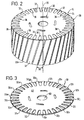
- the motor 10 is enclosed within a housing 12 and includes a rotor 14 and a stator 16.
- the stator 16 is the stationary portion of the motor 10 that is mounted to and within the housing 12.
- the stator 16 defines a longitudinal axis, indicated at 18, therethrough.
- the rotor 16 is the rotating portion of the motor 10 that is positioned within the stator 16.
- the rotor 14 defines a longitudinal axis, indicated at 20, and is aligned with the stator 16 such that the axes 18, 20 of the rotor 14 and stator 16 are collinear.
- the rotor 14 is positioned within the stator 16 to define a gap, referred to as an air gap, indicated at 22, therebetween.
- the gap 22 permits the rotor 14 to freely rotate within the stator 16 without the rotor 14 and stator 16 inadvertently contacting one another.
- the gap 22 can be about ten thousandths of an inch (10 mils).
- the gap 22 between the rotor 14 and stator 16 must be maintained in order to prevent the rotor 14 and stator 16 from contacting one another as the rotor 14 rotates. Given that the rotor 14 can rotate at speeds exceeding 3600 revolutions per minute (RPM), such contact can damage both the rotor 14 and stator 16 thus rendering the motor 10 inoperable.
- RPM revolutions per minute
- the gap 22 must be sufficiently small so that the electrical field that is created in the stator 16 can in turn induce an electrical field in the rotor 14. It is this induced electrical field in the rotor 14 that is converted to mechanical energy, and results in rotation of the rotor 14.
- the gap 22 must be sufficient to preclude contact between the rotor 14 and stator 16. As the gap 22 between the rotor 14 and stator 16 increases, the electrical field induced in the rotor 14 decreases.
- the size of the gap 22 between the rotor 14 and stator 16 must be determined balancing the need to maintain critical space between the components while maintaining the components sufficiently close to reduce and preferably minimize field losses.
- the rotor 14 and stator 16 each include a core 24, 26, respectively, that is formed of a plurality of plates or laminations 28 that are stacked together, one on another.
- a core 24, 26, respectively that is formed of a plurality of plates or laminations 28 that are stacked together, one on another.
- the laminations 28 are secured in place relative to one another by an interlocking system 30.
- the interlocking system 30 prevents the laminations 28 from rotating and shifting relative to one another and from separating from each other, and thus maintains the rotor core 24 as a unitary member during manufacture.
- the core 24 includes a predetermined number of slots 36 formed therein at an edge or periphery of each lamination 28.
- the slots 36 are defined by teeth 32a-32gg that separate the slots 36 from one another.
- the teeth 32a-32gg are integral with the lamination central portion.
- the spaces between the teeth 32a-32gg, that is the slots 36, are configured to receive and secure the conducting elements 34 therebetween.
- the conductors 34 are each formed as a single mass from, for example, aluminum that has been injected into the slots 36 in molten form. This type of rotor 14 manufacture is commonly referred to as a squirrel-cage motor.
- stator slots 36 extend outwardly from an inner edge of the stator laminations 28.
- stator 16 is formed in much the same manner as the rotor 14. It will be appreciated by those skilled in the art that the overall "circular" shape of the stator 16 is necessary only at an interior periphery, adjacent to the rotor 14.
- the plates or laminations 28 are generally formed from sheet material, such as sheet steel, that has been stamped in the form of the laminations 28.
- the individual laminations 28 are then stacked, one on another, to form the core 24.
- the characteristics of the material such as the thickness of the material, may not be uniform throughout the sheet. That is, the thickness of the material may vary. Although such a variance may not be critical for many applications, it can be critical for the manufacture of rotor and stator cores 24, 26, because the stacked core 24, 26 may exhibit asymmetries, e.g., lopsidedness, due to the varying lamination 28 thicknesses.
- the core 24 must be straight, that is, it must have a right-cylindrical form, so that the rotor 14 rotates within the stator 16 in a coaxial manner, without contacting the sides of the stator 16. It has been observed that an effective way to account for or accommodate the variation in lamination 28 thicknesses is to rotate the laminations 28 a predetermined number of degrees (e.g., 60, 90, 120) as they are formed to distribute the asymmetries about the entire 360 degrees of the core 24. This is referred to as "rotating" the core 24.
- the angle that the laminations 28 are rotated is referred to as the index angle, which includes the angle of rotation (or rotation angle) and any additional angle to account for skew.
- the rotation angle is dependent upon the number of interlocks and the number of slots in the core.
- a core that has twenty-four slots can have two interlocks and an angle of rotation of 180 degrees (or a multiple thereof), three interlocks and an angle of rotation of 120 degrees (or a multiple thereof), or four interlocks and an angle of rotation of 90 degrees (or a multiple thereof). While this appears to provide sufficient flexibility in core design, it is to be noted that this configuration does not permit the manufacture of rotated cores that have a prime number (e.g., 13, 17, 19, 23, 29, 37, 41, 43 and 47) of bars. Moreover, as stated above, problems have been observed with laminations rotated 180 degrees only.
- cores rotated only 180 degrees can exhibit an eccentricity which is an undesirable characteristic for a core.
- large rotational angles, e.g., 180 degrees, result in slower press speeds because of "communication" time between the manufacturing control system and the system servomotors and servo-drive systems.
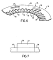
- the projection 38 has a lead portion 42 and a trailing portion 44.
- the lead portion 42 can be stepped, as shown in FIG. 5.
- the lead portion 42 is the uppermost raised portion from the surface 40 of the lamination 38.
- the trailing portion 44 can taper or ramp downwardly from the lead portion 42, sloping toward the surface 40 of the lamination 28.
- the projection 38 defines an arcuate shape along its circumferential length, as indicated by Lp, such that the centerline, as indicated at 46, remains at a fixed radial distance from the axis 20 of the lamination 38.
- the projections 38 of the present invention are received in projection receiving openings or regions 48 that are formed in the lamination 28.
- the receiving regions 48 are elongated to receive the projections 38 along the length L o of the region and to thus permit the projection 38 to reside fully within the region 48.
- the receiving region 48 is preferably arcuate such that a centerline, indicated at 50, of the receiving region 48 is at a fixed radial distance from the lamination axis 20.
- each receiving region 48 has a circumferential length L o that is somewhat longer than the length L p of its corresponding projection 38.
- the elongation of the receiving region 48 is adapted to accommodate a skew angle in, for example, the rotor core 24, if desired.
- the centerlines of the projections and the receiving regions 46, 50 are at the same radial distance from the lamination axis 20.
- the projection or projections 38 from one lamination 28 will reside wholly within the receiving region or regions 48 of an adjacent lamination 28.
- the present interlocking configuration is used to form rotor and stator cores 24, 26 having a prime number of slots 36.
- Each receiving opening 48 and its corresponding projection 38 are separated from one another by an angle ⁇ that is multiple of an angle ⁇ that is defined by 360 degrees/S, where S is the number of slots 36 in the lamination 28.
- ⁇ n ⁇
- ⁇ 360 ⁇ ° / S , where ⁇ is the separation angle between the projection 38 and its corresponding receiving opening 48, n is a whole number integer, ⁇ is the base angle, and S is the number of slots 36.
- the core 24, 26 that embodies the present interlocking configuration 30, can have any practical number of interlocks.
- Each lamination 28 can include a single projection 38 and receiving opening 48 or multiple projections 38 and receiving openings 48. It is, however, anticipated that for use in small motors 10, such as those having core 24 diameters less than about 2 inches, up to about nine interlock pairs, i.e., projections and corresponding receiving regions 38, 48 can be used. It will be apparent that as the size, i.e., diameter, of the motor 10 increases, the number of interlocks can increase.
- Such cores 24 can have any practical prime number of slots, including greater than about 59 and less than about seven slots.
- the illustrated core 24 includes a skew, indicated at 56, in the slots 36.
- a skew 56 can be included to, for example, reduce torque loss in the motor 10 or to reduce motor 10 "noise".
- the skew 56 is effected by offsetting the laminations 28 from one another by a relatively small angle (lamination skew angle) relative to the angle of rotation. That is, the skew angle is relatively small compared to the angle that the laminations 28 are rotated relative to one another to account for lamination 28 asymmetries.
- the skew angle is equal to about 360 degrees/T, where T is the number of stator slots 58.
- the skew angle can be about 360 degrees/24 or 15 degrees.
- the lamination skew angle for each lamination 28 is the total skew angle divided by the total number of laminations 28 in the stator 16.
- the skew angle for each lamination is 1 ⁇ 2 degree.
- the illustrated interlocking system 39 facilitates providing such a skew angle in the rotor core 24.
- the receiving regions 48 are somewhat longer circumferentially (as indicated at L o ) than their corresponding projections (indicted at L p ), to accommodate the slight offset to effect the core skew 56.
- adjacent laminations 28 can be positioned relative to one another, to accommodate both the angle of rotation and the smaller skew angle.
- the projections 38 can be received within the receiving regions 48 with a small amount of freedom for positioning, the skew angle can readily be accommodated between adjacent laminations 28.
- both skewed and non-skewed cores 24 can be fabricated using common rotor tooling and a common rotor design.
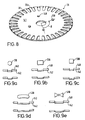
- FIGS. 8 and 9a-9e illustrate various alternate embodiments of projections that can be formed having various shapes. Each of the projections is formed without the trailing portion as shown in the embodiment of the projection 38 in FIGS. 2-7.
- the projection 138 can have a circular shape.
- the corresponding receiving opening 148 in such an embodiment can have a like circular shape or, alternately, can be formed having an elongated arcuate shape (not shown) to permit a degree of freedom of positioning the projection 138 within the opening.
- FIG. 9b a square 238 (FIG. 9b), a rectangle 338 (FIG. 9c), an elongated projection 438 (FIG. 9d), and a double ended, opposingly oriented triangle or bow-tie 538 (FIG. 9e) can also be used.
- Each of these embodiments of the projection can be formed with a ramped trailing portion, or the projection can be formed as a fully downwardly extending tab.
- the corresponding receiving openings can be formed having sufficient clearance or tolerance to permit a "tight" fit, or the openings can be configured to permit a degree of freedom for positioning the projection within the opening.
- the projections 238, 338, 438, and 538 can be formed by "punching" one surface or side 140 of the lamination 28 which forms the respective projection on the other side or surface 142 of the lamination 28.
- the respective projections can be formed having square or straight sides, or the projections can be formed having ramped or angled sides as illustrated. All such shapes and their corresponding opening configurations are within the scope of the present invention.
- end laminations 28e must be formed so that they engage or are engaged by only one adjacent lamination 28. That is, although the interior laminations 28 engage two adjacent laminations 28, the end laminations 28e engage or are engaged only by their respective interior lamination 28.
- the end lamination 28e is required only to receive the projections 38 from its adjacent lamination 28. This is readily accomplished by forming only receiving regions 48 in the lamination 28e.
- end laminations can be formed in a variety of configurations.
- end laminations 28e can be formed with projections 38 and receiving regions 48, and the lamination 28 can be rotated transverse to its axis (so that the projections 38 are in an opposing orientation to those of the stack laminations 28). In this arrangement, the projections 38 extend into the adjacent lamination 28, and the receiving regions 48 receive the projections 38 from the adjacent lamination 28. Alternately, the end lamination 28e can be oriented relative to its adjacent lamination 28 so that the projections 38 are urged back into the body of the lamination 28.
- interlocking system 30 has been, in part, described and illustrated with respect to a motor rotor core 24, the interlocking system 30 can be readily used to manufacture stator cores 26 as well as other cores that are formed as a stack of rotated laminations.
- One contemplated method for forming, for example, rotor laminations 28 includes positioning a stock material, such as sheet steel, in a die-cutting apparatus.
- the stock material is centralized and the rotor slots 36 (e.g., conductor receiving regions) are cut, such as by punching.
- vent holes can be also be cut, as can pilot holes for aligning the work piece as it traverses through the apparatus.
- the interlocking projections 38 are formed, such as by piercing or partial cutting through the stock material.
- Projection receiving regions 48 and a central bore 60 for a shaft 62 are also cut or punched.
- End laminations 28e are formed so as to engage or be engaged by only a single, adjacent lamination 28. In a preferred method, the end lamination 28e is formed by omitting the projection forming step.
- the receiving regions 48 and shaft bore 60 are formed in the material as are any other openings, penetrations or bores in the lamination 28. Other end lamination 28e forming steps may be used.
- the end lamination 28e can be formed by rotating the end lamination 28e transversely about its axis (e.g., turned over) so that the projections 38 on the end lamination 28e are opposingly oriented relative to the other lamination 28 projections 38.
- the projections 38 can be formed, such as by punching, in the opposing direction. End laminations can also be formed by punching all projections 38, rather than a combination of projections 38 and receiving regions 48.
- the rotor lamination 28 is then cut from the stock material and staked for alignment.
- the lamination 28 is rotated a predetermined angle, i.e., the index angle, from the cut position.
- the index angle is selected to effect the rotated core.
- the index angle is equal to the angle of rotation if there is no skew, and is equal to the angle of rotation plus the lamination skew angle if a skew is so desired.
- the laminations 28 are subsequently stacked, one on another, to form the rotor core 24.
- the stator laminations can be formed from the sheet material stock immediately adjacent and outward of the rotor formation after the rotor has been cut. Pilot holes are made in the material and, if it is so desired, the inner portion of the stator can be shaved to establish the space needed for the air gap.
- the stator slots are cut or pierced similar to the cutting of the rotor slots.
- Interlocking projections are formed, such as by piercing or partial cutting through the stock material. Projections receiving regions are also cut or punched.
- the stator laminations are then cut from the stock material and staked for alignment. The laminations can be rotated a predetermined angle from the cut position to rotate the stator laminations. The laminations are then stacked, one on another to form the stator.
Landscapes
- Engineering & Computer Science (AREA)
- Power Engineering (AREA)
- Manufacturing & Machinery (AREA)
- Iron Core Of Rotating Electric Machines (AREA)
- Manufacture Of Motors, Generators (AREA)
Applications Claiming Priority (2)
| Application Number | Priority Date | Filing Date | Title |
|---|---|---|---|
| US914100 | 1997-08-19 | ||
| US08/914,100 US5894182A (en) | 1997-08-19 | 1997-08-19 | Motor with rotor and stator core paired interlocks |
Publications (2)
| Publication Number | Publication Date |
|---|---|
| EP0898354A1 EP0898354A1 (en) | 1999-02-24 |
| EP0898354B1 true EP0898354B1 (en) | 2008-01-16 |
Family
ID=25433919
Family Applications (1)
| Application Number | Title | Priority Date | Filing Date |
|---|---|---|---|
| EP98306649A Expired - Lifetime EP0898354B1 (en) | 1997-08-19 | 1998-08-19 | Motor with rotor and stator core paired interlocks and forming method therefor |
Country Status (7)
| Country | Link |
|---|---|
| US (1) | US5894182A (enExample) |
| EP (1) | EP0898354B1 (enExample) |
| JP (1) | JPH11155246A (enExample) |
| KR (1) | KR19990023654A (enExample) |
| BR (1) | BR9803745A (enExample) |
| CA (1) | CA2245074C (enExample) |
| DE (1) | DE69838999T2 (enExample) |
Families Citing this family (65)
| Publication number | Priority date | Publication date | Assignee | Title |
|---|---|---|---|---|
| US5809638A (en) * | 1992-10-26 | 1998-09-22 | L.H. Carbide Corporation | Method for manufacturing laminated parts with center interlock |
| IT243439Y1 (it) * | 1997-10-31 | 2002-03-04 | Zanussi Elettromecc | Pacco rotorico perfezionato |
| US6002191A (en) * | 1998-06-19 | 1999-12-14 | General Electric Company | Paired interlocks for stacking of non-rotated lamination cores |
| DE19933009A1 (de) * | 1998-07-24 | 2000-02-10 | Matsushita Electric Industrial Co Ltd | Motor mit interne Permanentmagneten enthaltendem Rotor und einen solchen Motor verwendende Antriebseinheit |
| US6177749B1 (en) * | 1998-11-12 | 2001-01-23 | Emerson Electric Co. | Polygonal shaft hole rotor |
| US6341419B1 (en) * | 2000-02-29 | 2002-01-29 | General Electric Company | Loop stacked rotor assembly |
| BR0002187A (pt) * | 2000-03-30 | 2001-11-13 | Brasil Compressores Sa | Processo de formação de pacote anelar delâminas metálicas de estator de motor linear e opacote anelar de lâminas metálicas formado |
| JP3661582B2 (ja) * | 2000-09-28 | 2005-06-15 | 日産自動車株式会社 | 磁石モータ用ロータ |
| JP2002171701A (ja) * | 2000-11-30 | 2002-06-14 | Seiko Instruments Inc | スピンドルモータ |
| US6700287B2 (en) * | 2000-12-27 | 2004-03-02 | Asmo Co., Ltd. | Core of motor having core sheets stacked together and method for stacking the same |
| US7038350B2 (en) * | 2001-08-11 | 2006-05-02 | General Electric Company | Rotated reverse-direction-staple system and method |
| US6847285B2 (en) * | 2001-08-13 | 2005-01-25 | General Electric Company | Interlock tabs for laminations |
| US6975201B2 (en) * | 2001-08-11 | 2005-12-13 | General Electric Company | Reverse-direction-staple system and method |
| US6722015B2 (en) | 2001-08-11 | 2004-04-20 | General Electric Company | Assembly method for stamped and cupped laminations |
| JP2004080944A (ja) * | 2002-08-20 | 2004-03-11 | Toyota Motor Corp | 電動機用ステータコア |
| JP2004194497A (ja) * | 2002-11-29 | 2004-07-08 | Denso Corp | 回転電機の組み合わせ固定子コア |
| JP3687749B2 (ja) | 2003-04-23 | 2005-08-24 | 株式会社三井ハイテック | スキュー形状可変型積層鉄心及びその製造方法 |
| KR100584192B1 (ko) * | 2003-11-12 | 2006-05-29 | 한국코아 주식회사 | 적층 코아 제조 장치 및 이를 이용한 적층 코아 제조 방법 |
| DE102004008936A1 (de) * | 2004-02-25 | 2005-09-15 | Robert Bosch Gmbh | Anker für einen Gleichstrommotor |
| US7345396B2 (en) * | 2004-05-14 | 2008-03-18 | National-Oilwell, L.P. | Metallic laminations for magnetic circuits |
| WO2006045260A1 (de) * | 2004-10-28 | 2006-05-04 | Siemens Aktiengesellschaft | Elektrobleche mit abstandsstreifen und entsprechendes herstellungsverfahren |
| BRPI0500879A (pt) * | 2005-03-17 | 2006-11-14 | Brasil Compressores Sa | pacote de láminas metálicas, lámina metálica e processo de formação de um pacote de láminas |
| US8395288B2 (en) * | 2005-09-21 | 2013-03-12 | Calnetix Technologies, L.L.C. | Electric machine with centrifugal impeller |
| CH698519B1 (de) * | 2006-01-24 | 2009-08-31 | Alstom Technology Ltd | Pressplattenbleche eines Statorblechkörpers einer elektrischen Maschine. |
| US20070247015A1 (en) * | 2006-04-25 | 2007-10-25 | A. O. Smith Corporation | Rotor having lobed bore and method of assembling same |
| DE102006026402A1 (de) * | 2006-06-07 | 2007-12-13 | Robert Bosch Gmbh | Wechselstromgenerator für Kraftfahrzeuge |
| JP2008029169A (ja) * | 2006-07-25 | 2008-02-07 | Mitsui High Tec Inc | 積層鉄心 |
| US7710081B2 (en) | 2006-10-27 | 2010-05-04 | Direct Drive Systems, Inc. | Electromechanical energy conversion systems |
| WO2008113018A1 (en) * | 2007-03-15 | 2008-09-18 | Direct Drive Systems, Inc. | Cooling an electrical machine |
| US7841306B2 (en) * | 2007-04-16 | 2010-11-30 | Calnetix Power Solutions, Inc. | Recovering heat energy |
| US8839622B2 (en) * | 2007-04-16 | 2014-09-23 | General Electric Company | Fluid flow in a fluid expansion system |
| US7638892B2 (en) * | 2007-04-16 | 2009-12-29 | Calnetix, Inc. | Generating energy from fluid expansion |
| DE102008032844A1 (de) * | 2008-07-14 | 2010-01-21 | Hanning Elektro-Werke Gmbh & Co. Kg | Permanentmagnetischer Rotor |
| US8253298B2 (en) | 2008-07-28 | 2012-08-28 | Direct Drive Systems, Inc. | Slot configuration of an electric machine |
| JP5341614B2 (ja) * | 2009-05-14 | 2013-11-13 | 株式会社三井ハイテック | 積層鉄心の製造方法及び積層鉄心 |
| JP5212273B2 (ja) * | 2009-07-01 | 2013-06-19 | 三菱電機株式会社 | 積層コア |
| EP2473364B1 (en) * | 2009-08-31 | 2019-09-25 | Multiple Electric Systems, L.L.C. | Multiple induction electric motor and vehicle |
| KR101005911B1 (ko) * | 2010-05-04 | 2011-01-06 | 주식회사비.엠.씨 | 전기강판 코어 |
| US8739538B2 (en) | 2010-05-28 | 2014-06-03 | General Electric Company | Generating energy from fluid expansion |
| JP5510285B2 (ja) * | 2010-11-18 | 2014-06-04 | アイシン・エィ・ダブリュ株式会社 | 回転電機のロータコア |
| US8674580B2 (en) * | 2011-11-16 | 2014-03-18 | Remy Technologies, Llc | Electric machine with end ring and supporting tab |
| DE102011122023A1 (de) * | 2011-12-23 | 2013-06-27 | Brose Fahrzeugteile GmbH & Co. Kommanditgesellschaft, Würzburg | Roboterblechpaket eines Elektromotors |
| US8984884B2 (en) | 2012-01-04 | 2015-03-24 | General Electric Company | Waste heat recovery systems |
| US9024460B2 (en) | 2012-01-04 | 2015-05-05 | General Electric Company | Waste heat recovery system generator encapsulation |
| US9018778B2 (en) | 2012-01-04 | 2015-04-28 | General Electric Company | Waste heat recovery system generator varnishing |
| DE102012220382A1 (de) * | 2012-04-17 | 2013-10-17 | Siemens Aktiengesellschaft | Polschuhanordnung für ein Maschinenelement einer elektrischen Maschine |
| US20130342065A1 (en) * | 2012-05-08 | 2013-12-26 | Asmo Co., Ltd. | Brushless motor and method for manufacturing brushless motor |
| JP6050084B2 (ja) * | 2012-10-19 | 2016-12-21 | ミネベア株式会社 | スピンドルモータおよびハードディスク駆動装置 |
| DE102012022084A1 (de) | 2012-11-09 | 2014-05-15 | Volkswagen Aktiengesellschaft | Rotoranordnung für eine elektrische Maschine, elektrische Maschine und Verfahren zum Herstellen der Rotoranordnung |
| US20140154115A1 (en) * | 2012-11-30 | 2014-06-05 | Emerson Electric Co. | Scroll Compressor Having A Single Phase Induction Motor With Aluminum Windings |
| US20140246943A1 (en) * | 2013-03-01 | 2014-09-04 | GM Global Technology Operations LLC | Optimum rotor skew angle for an electric machine |
| EP2819275A1 (de) * | 2013-06-28 | 2014-12-31 | HILTI Aktiengesellschaft | Verschiebliches Statorpaket |
| EP2819274A1 (de) * | 2013-06-28 | 2014-12-31 | HILTI Aktiengesellschaft | Verschiebliches Rotorpaket |
| DE102013215812A1 (de) * | 2013-08-09 | 2015-03-05 | Bühler Motor GmbH | Elektrische Maschine |
| US9806587B2 (en) | 2013-08-26 | 2017-10-31 | Robert Ross | System and method for stator construction of an electric motor |
| DE102015211738A1 (de) * | 2015-06-24 | 2016-12-29 | Robert Bosch Gmbh | Elektrische Maschine |
| CN106504863B (zh) * | 2016-10-14 | 2018-03-09 | 嵊州市仲明新材料科技有限公司 | 一种可散热的铁芯 |
| DE102016225890B3 (de) | 2016-12-21 | 2018-05-30 | Magna powertrain gmbh & co kg | Rotor für eine elektrische Maschine |
| JP2018207632A (ja) * | 2017-06-01 | 2018-12-27 | 株式会社東芝 | 電動機 |
| CN109980806A (zh) * | 2017-12-28 | 2019-07-05 | 丹佛斯(天津)有限公司 | 电机转子和电机 |
| US11296569B2 (en) | 2018-07-12 | 2022-04-05 | Zunum Aero, Inc. | Multi-filar coil winding for electric machine |
| US11387764B2 (en) | 2018-07-12 | 2022-07-12 | Zunum Aero, Inc. | Multi-inverter system for electric machine |
| US11196310B2 (en) | 2018-07-30 | 2021-12-07 | Zunum Aero, Inc. | Permanent magnet assemblies for a cylinder of an electrical machine |
| US11056936B2 (en) | 2019-04-15 | 2021-07-06 | Ford Global Technologies, Llc | Electric motor and construction methods thereof |
| US11522427B2 (en) | 2020-08-28 | 2022-12-06 | Emerson Electric Co. | Single phase induction motors including aluminum windings and high permeability low coreloss steel |
Family Cites Families (18)
| Publication number | Priority date | Publication date | Assignee | Title |
|---|---|---|---|---|
| US3203077A (en) * | 1961-07-19 | 1965-08-31 | Gen Motors Corp | Fastening assembly and procedure |
| US3202851A (en) * | 1961-07-19 | 1965-08-24 | Gen Motors Corp | Method and means for aligning and fastening laminations of dynamoelectric machine |
| US3590208A (en) * | 1967-11-02 | 1971-06-29 | Licentia Gmbh | Method of aligning and welding laminated sheets for electrical machines |
| US4110895A (en) * | 1977-07-27 | 1978-09-05 | Mitsui Mfg. Co., Ltd. | Apparatus for manufacturing laminated cores |
| US4272579A (en) * | 1977-07-27 | 1981-06-09 | Mitsui Mfg. Co., Ltd. | Laminated stack manufacture |
| US4160182A (en) * | 1977-07-27 | 1979-07-03 | Mitsui Mfg. Co., Ltd. | Laminated core manufacture |
| JPS5795158A (en) * | 1980-12-02 | 1982-06-12 | Toshiba Corp | Rotary electric machine |
| DE3174871D1 (en) * | 1981-03-31 | 1986-07-31 | Matsushita Electric Industrial Co Ltd | Iron core laminate manufacturing apparatus |
| US4738020A (en) * | 1983-03-25 | 1988-04-19 | L H Carbide Corporation | Method for manufacture of laminated parts |
| US4619028A (en) * | 1983-03-25 | 1986-10-28 | L H Carbide Corporation | Apparatus for manufacture of laminated parts |
| US5123155A (en) * | 1983-03-25 | 1992-06-23 | L. H. Carbide Corporation | Apparatus and method for manufacturing laminated parts |
| US5087849A (en) * | 1983-03-25 | 1992-02-11 | L H Carbide Corporation | Laminated parts and a method for manufacture thereof |
| JPS6092023A (ja) * | 1983-09-30 | 1985-05-23 | Mitsui Haitetsuku:Kk | 積層鉄芯製造用順送り金型装置 |
| US5142178A (en) * | 1991-04-12 | 1992-08-25 | Emerson Electric Co. | Apparatus for aligning stacked laminations of a dynamoelectric machine |
| JPH05168178A (ja) * | 1991-12-16 | 1993-07-02 | Mitsubishi Electric Corp | 回転電機の固定子鉄心 |
| US5349741A (en) * | 1992-06-24 | 1994-09-27 | L.H. Carbide Corporation | Method of making an interlocked core spaced for anneal penetration |
| JPH0614481A (ja) * | 1992-06-25 | 1994-01-21 | Mitsubishi Electric Corp | 電機子鉄心 |
| US5649349A (en) * | 1995-05-05 | 1997-07-22 | Greenway; Glenn W. | Method for manufacturing of laminated components |
-
1997
- 1997-08-19 US US08/914,100 patent/US5894182A/en not_active Expired - Lifetime
-
1998
- 1998-08-13 CA CA002245074A patent/CA2245074C/en not_active Expired - Fee Related
- 1998-08-18 BR BR9803745-5A patent/BR9803745A/pt not_active Application Discontinuation
- 1998-08-18 KR KR1019980033387A patent/KR19990023654A/ko not_active Abandoned
- 1998-08-18 JP JP10231280A patent/JPH11155246A/ja active Pending
- 1998-08-19 DE DE69838999T patent/DE69838999T2/de not_active Expired - Lifetime
- 1998-08-19 EP EP98306649A patent/EP0898354B1/en not_active Expired - Lifetime
Also Published As
| Publication number | Publication date |
|---|---|
| CA2245074C (en) | 2005-10-25 |
| US5894182A (en) | 1999-04-13 |
| BR9803745A (pt) | 1999-11-23 |
| DE69838999T2 (de) | 2008-12-24 |
| CA2245074A1 (en) | 1999-02-19 |
| EP0898354A1 (en) | 1999-02-24 |
| JPH11155246A (ja) | 1999-06-08 |
| DE69838999D1 (de) | 2008-03-06 |
| KR19990023654A (ko) | 1999-03-25 |
Similar Documents
| Publication | Publication Date | Title |
|---|---|---|
| EP0898354B1 (en) | Motor with rotor and stator core paired interlocks and forming method therefor | |
| US6223417B1 (en) | Method for forming motor with rotor and stator core paired interlocks | |
| US6018207A (en) | Paired interlocks for flexible indexing of rotated stator cores | |
| US6002191A (en) | Paired interlocks for stacking of non-rotated lamination cores | |
| JPH11155246A5 (enExample) | ||
| US6744171B1 (en) | Rotating electric machine with sloped tooth surfaces for cogging torque reduction | |
| CN101057381B (zh) | 永磁转子 | |
| US8106561B2 (en) | Laminated core and method for manufacturing the same | |
| JP5565365B2 (ja) | 回転電機のロータおよびその製造方法 | |
| EP2259409B1 (en) | Rotating electric machine and manufacturing method thereof | |
| US11159066B2 (en) | Rotary electric machine and rotor mounted therein | |
| EP2621060B1 (en) | Winding structure, rotating electric machine, and rotating electric machine manufacturing method | |
| US7245054B1 (en) | Permanent magnet electric machine having reduced cogging torque | |
| EP0052179A1 (en) | Axial flux electric machine | |
| US20220368183A1 (en) | Rotor for a synchronous machine | |
| US20190148997A1 (en) | Stator, block of stator, and rotary electrical machine | |
| JP6136477B2 (ja) | 回転電機およびその製造方法 | |
| US11316393B2 (en) | Magnetic sheet for rotor with a non-through shaft, method of obtaining such a sheet and associated rotor | |
| JP6508102B2 (ja) | 回転電機、および分割ステータ鋼板の製造方法 | |
| CN115118032A (zh) | 用于电机的定子基体以及具有定子基体的电机和用于制造定子基体的方法 | |
| MXPA98006726A (en) | Engine with interlocks in rotor and stator nucleus pairs and its formac method | |
| US20250167609A1 (en) | Mechanical retention of rotor magnets | |
| US20250211042A1 (en) | Rotating electric machine core and rotating electric machine | |
| JP7484777B2 (ja) | 回転電機 | |
| US20150318742A1 (en) | Electric machines, stators and compressors and methods of manufacturing same |
Legal Events
| Date | Code | Title | Description |
|---|---|---|---|
| PUAI | Public reference made under article 153(3) epc to a published international application that has entered the european phase |
Free format text: ORIGINAL CODE: 0009012 |
|
| AK | Designated contracting states |
Kind code of ref document: A1 Designated state(s): DE FR GB IT SE |
|
| AX | Request for extension of the european patent |
Free format text: AL;LT;LV;MK;RO;SI |
|
| 17P | Request for examination filed |
Effective date: 19990824 |
|
| AKX | Designation fees paid |
Free format text: DE FR GB IT SE |
|
| 17Q | First examination report despatched |
Effective date: 20041207 |
|
| GRAP | Despatch of communication of intention to grant a patent |
Free format text: ORIGINAL CODE: EPIDOSNIGR1 |
|
| GRAS | Grant fee paid |
Free format text: ORIGINAL CODE: EPIDOSNIGR3 |
|
| GRAA | (expected) grant |
Free format text: ORIGINAL CODE: 0009210 |
|
| AK | Designated contracting states |
Kind code of ref document: B1 Designated state(s): DE FR GB IT SE |
|
| REG | Reference to a national code |
Ref country code: GB Ref legal event code: FG4D |
|
| REF | Corresponds to: |
Ref document number: 69838999 Country of ref document: DE Date of ref document: 20080306 Kind code of ref document: P |
|
| REG | Reference to a national code |
Ref country code: SE Ref legal event code: TRGR |
|
| PLBE | No opposition filed within time limit |
Free format text: ORIGINAL CODE: 0009261 |
|
| STAA | Information on the status of an ep patent application or granted ep patent |
Free format text: STATUS: NO OPPOSITION FILED WITHIN TIME LIMIT |
|
| 26N | No opposition filed |
Effective date: 20081017 |
|
| PGFP | Annual fee paid to national office [announced via postgrant information from national office to epo] |
Ref country code: DE Payment date: 20140827 Year of fee payment: 17 |
|
| PGFP | Annual fee paid to national office [announced via postgrant information from national office to epo] |
Ref country code: FR Payment date: 20140818 Year of fee payment: 17 Ref country code: GB Payment date: 20140827 Year of fee payment: 17 Ref country code: SE Payment date: 20140827 Year of fee payment: 17 |
|
| PGFP | Annual fee paid to national office [announced via postgrant information from national office to epo] |
Ref country code: IT Payment date: 20140826 Year of fee payment: 17 |
|
| REG | Reference to a national code |
Ref country code: DE Ref legal event code: R119 Ref document number: 69838999 Country of ref document: DE |
|
| REG | Reference to a national code |
Ref country code: SE Ref legal event code: EUG |
|
| GBPC | Gb: european patent ceased through non-payment of renewal fee |
Effective date: 20150819 |
|
| PG25 | Lapsed in a contracting state [announced via postgrant information from national office to epo] |
Ref country code: IT Free format text: LAPSE BECAUSE OF NON-PAYMENT OF DUE FEES Effective date: 20150819 |
|
| PG25 | Lapsed in a contracting state [announced via postgrant information from national office to epo] |
Ref country code: SE Free format text: LAPSE BECAUSE OF NON-PAYMENT OF DUE FEES Effective date: 20150820 |
|
| REG | Reference to a national code |
Ref country code: FR Ref legal event code: ST Effective date: 20160429 |
|
| PG25 | Lapsed in a contracting state [announced via postgrant information from national office to epo] |
Ref country code: DE Free format text: LAPSE BECAUSE OF NON-PAYMENT OF DUE FEES Effective date: 20160301 Ref country code: GB Free format text: LAPSE BECAUSE OF NON-PAYMENT OF DUE FEES Effective date: 20150819 |
|
| PG25 | Lapsed in a contracting state [announced via postgrant information from national office to epo] |
Ref country code: FR Free format text: LAPSE BECAUSE OF NON-PAYMENT OF DUE FEES Effective date: 20150831 |