EP0898102A2 - Fluidbetätigter Arbeitszylinder - Google Patents
Fluidbetätigter Arbeitszylinder Download PDFInfo
- Publication number
- EP0898102A2 EP0898102A2 EP98113640A EP98113640A EP0898102A2 EP 0898102 A2 EP0898102 A2 EP 0898102A2 EP 98113640 A EP98113640 A EP 98113640A EP 98113640 A EP98113640 A EP 98113640A EP 0898102 A2 EP0898102 A2 EP 0898102A2
- Authority
- EP
- European Patent Office
- Prior art keywords
- piston rod
- working cylinder
- control valve
- cylinder according
- magnet armature
- Prior art date
- Legal status (The legal status is an assumption and is not a legal conclusion. Google has not performed a legal analysis and makes no representation as to the accuracy of the status listed.)
- Granted
Links
Images
Classifications
-
- F—MECHANICAL ENGINEERING; LIGHTING; HEATING; WEAPONS; BLASTING
- F15—FLUID-PRESSURE ACTUATORS; HYDRAULICS OR PNEUMATICS IN GENERAL
- F15B—SYSTEMS ACTING BY MEANS OF FLUIDS IN GENERAL; FLUID-PRESSURE ACTUATORS, e.g. SERVOMOTORS; DETAILS OF FLUID-PRESSURE SYSTEMS, NOT OTHERWISE PROVIDED FOR
- F15B15/00—Fluid-actuated devices for displacing a member from one position to another; Gearing associated therewith
- F15B15/08—Characterised by the construction of the motor unit
- F15B15/14—Characterised by the construction of the motor unit of the straight-cylinder type
- F15B15/1423—Component parts; Constructional details
- F15B15/1433—End caps
-
- F—MECHANICAL ENGINEERING; LIGHTING; HEATING; WEAPONS; BLASTING
- F15—FLUID-PRESSURE ACTUATORS; HYDRAULICS OR PNEUMATICS IN GENERAL
- F15B—SYSTEMS ACTING BY MEANS OF FLUIDS IN GENERAL; FLUID-PRESSURE ACTUATORS, e.g. SERVOMOTORS; DETAILS OF FLUID-PRESSURE SYSTEMS, NOT OTHERWISE PROVIDED FOR
- F15B13/00—Details of servomotor systems ; Valves for servomotor systems
- F15B13/02—Fluid distribution or supply devices characterised by their adaptation to the control of servomotors
- F15B13/04—Fluid distribution or supply devices characterised by their adaptation to the control of servomotors for use with a single servomotor
- F15B13/0401—Valve members; Fluid interconnections therefor
- F15B13/0405—Valve members; Fluid interconnections therefor for seat valves, i.e. poppet valves
-
- F—MECHANICAL ENGINEERING; LIGHTING; HEATING; WEAPONS; BLASTING
- F15—FLUID-PRESSURE ACTUATORS; HYDRAULICS OR PNEUMATICS IN GENERAL
- F15B—SYSTEMS ACTING BY MEANS OF FLUIDS IN GENERAL; FLUID-PRESSURE ACTUATORS, e.g. SERVOMOTORS; DETAILS OF FLUID-PRESSURE SYSTEMS, NOT OTHERWISE PROVIDED FOR
- F15B13/00—Details of servomotor systems ; Valves for servomotor systems
- F15B13/02—Fluid distribution or supply devices characterised by their adaptation to the control of servomotors
- F15B13/04—Fluid distribution or supply devices characterised by their adaptation to the control of servomotors for use with a single servomotor
- F15B13/044—Fluid distribution or supply devices characterised by their adaptation to the control of servomotors for use with a single servomotor operated by electrically-controlled means, e.g. solenoids, torque-motors
-
- F—MECHANICAL ENGINEERING; LIGHTING; HEATING; WEAPONS; BLASTING
- F15—FLUID-PRESSURE ACTUATORS; HYDRAULICS OR PNEUMATICS IN GENERAL
- F15B—SYSTEMS ACTING BY MEANS OF FLUIDS IN GENERAL; FLUID-PRESSURE ACTUATORS, e.g. SERVOMOTORS; DETAILS OF FLUID-PRESSURE SYSTEMS, NOT OTHERWISE PROVIDED FOR
- F15B15/00—Fluid-actuated devices for displacing a member from one position to another; Gearing associated therewith
- F15B15/08—Characterised by the construction of the motor unit
- F15B15/14—Characterised by the construction of the motor unit of the straight-cylinder type
- F15B15/149—Fluid interconnections, e.g. fluid connectors, passages
-
- F—MECHANICAL ENGINEERING; LIGHTING; HEATING; WEAPONS; BLASTING
- F15—FLUID-PRESSURE ACTUATORS; HYDRAULICS OR PNEUMATICS IN GENERAL
- F15B—SYSTEMS ACTING BY MEANS OF FLUIDS IN GENERAL; FLUID-PRESSURE ACTUATORS, e.g. SERVOMOTORS; DETAILS OF FLUID-PRESSURE SYSTEMS, NOT OTHERWISE PROVIDED FOR
- F15B15/00—Fluid-actuated devices for displacing a member from one position to another; Gearing associated therewith
- F15B15/20—Other details, e.g. assembly with regulating devices
- F15B15/202—Externally-operated valves mounted in or on the actuator
Definitions
- the invention relates to a fluid-operated cylinder, with a housing that is one of two front End walls contain limited space, in which there is an axially displaceable piston, the with at least one penetrating the front end wall Piston rod is connected, the front End wall with at least one for controlling the application of fluid serving the piston, electromagnetic Actuatable control valve is equipped, the at least one Solenoid and one associated with it, for actuation serving at least one control section of the control valve has movable magnet armature.
- a pneumatically operated cylinder of this type emerges from DE 44 39 667 A1.
- This well-known Working cylinder is in the lid-like front End wall integrated a control valve that is cartridge-like executed and in a recess to the side of the Piston rod is inserted.
- one fluid-operated cylinder of the type mentioned to create a combination of control valve and End cover allows and higher flow rates and promises better heat dissipation.
- the piston rod in the invention Design of the control valve ring-shaped enclosed, the piston rod both the solenoid as well as the magnet armature. Because the possibility there is at least one control section also ring-shaped perform so that they are around the piston rod extends around, even with only a small switching movement the armature has a relatively large flow cross-section be made available what the achievement enables high flow values.
- an annular magnet coil can also be used, which has a sufficiently large diameter to as a result of the larger outer surface to ensure good heat dissipation. It also has proven that when using solenoids larger diameter a better utilization of the magnetic flux results. This makes it possible to have higher switching forces to realize or the required switching forces with to generate little energy.
- the arrangement is preferably such that the direction of movement of the magnet armature parallel to the direction of movement the piston rod is aligned.
- At least a control valve coaxial with respect to the one passing through it Arrange the piston rod.
- a suitable embodiment provides for the control valve to be designed as a 3/2-way valve and in terms of fluid technology with one of those separated from the piston in the receiving space Working chambers link that either a connection with a feed channel or a connection with a discharge channel is present while the connection is in progress to the other channel is interrupted.
- a control valve with a comparable function can also be added to the rear end wall are provided to the feed and discharge of pressure medium with respect to the other working chamber to control and tune the working cylinder Operation of the control valves.
- a control valve with a comparable function can also be added to the rear end wall are provided to the feed and discharge of pressure medium with respect to the other working chamber to control and tune the working cylinder Operation of the control valves.
- an intra-cylinder link between the two Control valves possible to easily for example to implement a 5/2-way function.
- a particularly compact working cylinder in the axial direction results when the magnetic armature the annular disk-shaped area projecting axially in front of the coil Has anchor section.
- This can with be combined with a hollow cylindrical anchor section, which in particular as a guide when moving the magnet armature can serve.
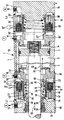
- the working cylinder of the exemplary embodiment becomes pneumatic operated. It has an elongated housing 1, in which a cylindrical receiving space 2 is formed, in which there is an axially displaceable piston 3. On the circumference, the receiving space 2 is of a tubular shape Housing part 4 and on its two axial sides bounded by a respective end wall 5, 6. The end walls 5, 6 are in the embodiment of separate, attached to the front of the tubular housing part 4 End caps 7, 8 formed.
- piston rod 12 set extends to the front of the housing 1 and the front end wall 5 is axially displaceable.
- a fastening device At the section of the piston rod lying outside the housing 1 12 is a fastening device, not shown provided that the attachment of a by the Working cylinder to be relocated component.
- the piston 3 divides the receiving space 2 into a front one and a rear working chamber 13, 14.
- Each of these Working chambers 13, 14 are in the adjacent end wall 5, 6 a feed channel which can be connected to a pressure source P. 15, 15 'and a discharge channel leading to a pressure sink R. 16, 16 'assigned.
- the latter is in the execution example a ventilation channel that communicates with the atmosphere.
- Each end cover 7, 8 is electromagnetic Actuatable control valve 17, 18 equipped, according to the example is designed as a 3/2-way valve. It is between a feed position and a discharge position switchable, in which either the feed channel 15, 15 'or the discharge duct 16, 16 'with the adjacent working chamber 13, 14 is connected, the other channel being blocked off is. In this way, the two-sided Fluid application of the piston 3 to control this together with the piston rod 12 axially according to double arrow 22 to shift in one direction or the other.
- Both control valves 17, 18 each have, among other things via a magnet coil 23, 23 'fixed to the housing with which is a movable magnet armature 24, 24 'in operative connection stands.
- the magnet armature 24, 24 ' is used for actuation at least one and in the embodiment for actuation two control sections 25, 26; 25 ', 26' which in Interact with an associated valve seat 27, 28; 27 ', 28' the fluid supply and fluid removal already mentioned Taxes.
- the actuation is by electrical actuation signals evoked that about electrical Conductors 32, 32 'of the magnetic coil 23, 23' are fed, so that it is excited and generates a magnetic field that causes the movement of the armature 24, 24 '.
- a great advantage of the working cylinder results from that the provided on the front end cover 7 front Control valve 17 is designed and arranged such that his solenoid 23 and the armature 24 of the Piston rod 12 are penetrated. Beyond that runs the direction of movement 33 indicated by double arrow 33 of the magnet armature 24 parallel to the direction of movement 22 of the Piston rod 12. This results in a total a compact arrangement, the high flow values for the Pressure medium ensures high switching forces and good heat dissipation from that generated by the solenoid 23 Guaranteed warmth.
- a hinged anchor could also be provided for the magnet anchor be a kind of folding or swiveling movement as a switching movement executes.
- the control valve 17 is preferably annular as shown executed and arranged so that it is the piston rod 12 coaxially encloses in the area of its outer circumference.
- the front cover 7 is constructed in several parts and has two axially spaced annular ones Cover parts 34, 35 ', between which the front control valve 17 is clamped.
- the two cover parts 34, 35 can together with the control valve 17 by a screw connection indicated by dash-dotted lines 36 firmly screwed to the tubular housing part 4 be.
- the axial penetrated by the piston rod 12 Opening 37 of the front cover 7 settles by axially successive lengths in the two cover parts 34, 35 and in the associated control valve 17 together.
- an annular sealing device 38 and an annular guide device 39 are provided, which enclose the piston rod 12 and work with them in a sealing or leading manner.
- the exemplary front control valve has 17 via an annular housing part 42 with which it between the two, also similar to ring disks Cover parts 34, 35 is fixed.
- annular housing part 42 In a recess of the ring-shaped housing part 42 is also ring-shaped, Magnetic coil with a short construction in the axial direction 23 housed, of which the electrical conductor 32nd going out.
- the fixation on the annular housing part 42 can in particular by a fastening device 43 Shape of a screw connection.
- annular space 44 Radially between the housing part 42 and the piston rod 12 an annular space 44 is provided. In him there is a hollow cylindrical anchor portion 45 of Magnetic armature 24, with its outer surface on the inner surface of the annular housing part 42 axially displaceable is led. A cylindrical cooperating between them Areas arranged and expediently on Magnet armature 24 fixed sealing ring 46 prevents flow through the compressed air between the mentioned, relative moving parts.
- the magnet armature 24 also has an am an end region of the hollow cylindrical anchor section 45 arranged annular disc-shaped anchor portion 47, the radially outward into one of the solenoid 23 axially extends upstream area. In the embodiment protrudes the ring-shaped anchor portion 47 on the Receiving space 2 facing the axial side in front of the solenoid 23.
- the two aforementioned control sections 25, 26 of the front Control valve 17 are oriented axially opposite and are in the execution example on the two axially opposite end portions of the armature 24. They are each of annular parts of the Magnet armature formed, which in one case on the Receiving space 2 facing the face of the annular disc Anchor section 47 and in the other case on the opposite front end area of the hollow cylindrical Anchor section 45 are.
- valve seats 27, 28 already mentioned are also annular and enclose the piston rod 12 concentric, being the assigned tax section 25, 26 lie axially opposite.
- the valve seats 27, 28 are provided fixed to the housing on the front end wall 5 and are located, for example, on the control valve 17 facing axial side of the two cover parts 34, 35.
- Spring device 48 is supported between the front end wall 5 and the armature 24 from, the latter biased in an unactuated position, which in the embodiment corresponds to the discharge position.
- the one control section 26 axially from the associated valve seat 28 lifted off so that there is an annular overflow gap 52 results in a running in the front end wall 5, the piston rod 12 coaxially surrounding annulus 53 with an example formed in the outer cover part 34 annular discharge chamber 54 connects the communicates with the discharge channel 16. Since the annular space 53 by means of the sealing device 38 to the atmosphere is sealed, but elsewhere to the subsequent one front working chamber 13 is open, can the pressure medium located in the front working chamber 13 discharge according to arrow 55. If the rear working chamber 14 pressure medium supplied, the piston 3 moves forward and the piston rod 12 extends.
- the magnet armature 24 with the control sections 25, 26 forms in the embodiment, the movable valve member Control valve 17. Overall, it is ring or sleeve-like executed and has an opening, through which the piston rod 12 with all-round extends radial distance, so that the function of the control valve 17 does not depend on the movement of the piston rod 12 is affected.
- the concrete form of the magnet armature used in the embodiment 24 could be described as "hat-like".
- piston rod 12 which consists of non-magnetizable material, for example Aluminum material. This is an influencing of the magnetic field generated by the magnetic coil 23 locked out. But it would also be conceivable that Piston rod and possibly also the ring-shaped housing part 42 involved in the generation of the magnetic field, by making one or both of these ferromagnetic parts Manufactures material.
- the exemplary embodiment of the magnet armature 24 enables pressure compensation, which results in that at least in the unactuated position and expediently practical even in the actuated position no differential forces resulting from the fluid pressure on the Act magnetic armature 24.
- the unactuated position can thus already with a relatively weak spring device 48 can be ensured so that the switching process can proceed at high speed.
- the working cylinder can be seen with a Solenoid 23 relatively large coil diameter equip without this adversely affecting the size of the working cylinder affects. Stand as installation space practically the entire transverse dimensions of the working cylinder available in the circumferential area of the piston rod 12. This enables the realization of high switching forces and also a large one that promotes heat dissipation Coil surface.
- the control valve could also be several, for example two Have solenoids that are conveniently coaxial are arranged to each other and both from the piston rod be enforced.
- the two control valves 17, 18 can be matched operate in such a way that the piston 3 with the piston rod 12 performs a desired axial movement. A positioning too in a desired axial position it is possible although this is with a modified structure of the Working cylinder would be possible more precisely.
- This modified Design sees a multi-stage in the respective end cover Valve structure before, each by several and preferably two control valves of the same construction axially in succession are installed.
- this refers both circular and non-circular and for example elliptical or oval cross-sectional shapes.
- the non-circular cross-sectional shape can in particular then be an advantage if the piston rod has a non-circular cross-section. It is advisable to at least fit the inside cross section of the magnet armature to the outer contour of the piston rod.
Landscapes
- Engineering & Computer Science (AREA)
- Physics & Mathematics (AREA)
- Fluid Mechanics (AREA)
- Mechanical Engineering (AREA)
- General Engineering & Computer Science (AREA)
- Actuator (AREA)
- Magnetically Actuated Valves (AREA)
Abstract
Description
Claims (16)
- Fluidbetätigter Arbeitszylinder, mit einem Gehäuse (1), das einen von zwei stirnseitigen Abschlußwänden (5, 6) begrenzten Aufnahmeraum (2) enthält, in dem sich ein axial verschiebbarer Kolben (3) befindet, der mit einer zumindest die vordere Abschlußwand (5) durchsetzenden Kolbenstange (12) verbunden ist, wobei die vordere Abschlußwand (5) mit wenigstens einem zur Steuerung der Fluidbeaufschlagung des Kolbens (3) dienenden, elektromagnetisch betätigbaren Steuerventil (17) ausgestattet ist, das wenigstens eine Magnetspule (23) und einen dieser zugeordneten, zur Betätigung wenigstens einer Steuerpartie (25, 26) des Steuerventils (17) dienenden beweglichen Magnetanker (24) aufweist, dadurch gekennzeichnet, daß die Magnetspule (23) und der Magnetanker (24) des Steuerventils (17) von der Kolbenstange (12) durchsetzt werden.
- Arbeitszylinder nach Anspruch 1, dadurch gekennzeichnet, daß die Bewegungsrichtung (33) des Magnetankers zumindest im wesentichen (24) parallel zu derjenigen (22) der Kolbenstange (12) verläuft.
- Arbeitszylinder nach Anspruch 1 oder 2, dadurch gekennzeichnet, daß die Kolbenstange (12) von der Magnetspule (23) und vom Magnetanker (24) des Steuerventils (17) unter koaxialer Anordnung umschlossen wird.
- Arbeitszylinder nach einem der Ansprüche 1 bis 3, dadurch gekennzeichnet, daß die wenigstens eine Steuerpartie (25, 26) des Steuerventils (17) die Kolbenstange (12) umschließt und axial einem die Kolbenstange (12) ebenfalls umschließenden gehäusefesten ringförmigen Ventilsitz (27, 28) gegenüberliegt.
- Arbeitszylinder nach Anspruch 4, dadurch gekennzeichnet, daß das Steuerventil (17) zwei axial entgegengesetzt orientierte Steuerpartien (25, 26) aufweist, die jeweils einem gehäusefesten ringförmigen Ventilsitz (27, 28) gegenüberliegen, wobei die eine Steuerpartie (25) die Fluidzufuhr und die andere Steuerpartie (26) die Fluidabfuhr bezüglich einer der vom Kolben (3) im Aufnahmeraum (2) abgeteilten Arbeitskammern (13, 14) und dabei insbesondere bezüglich der vorderen Arbeitskammer (13) steuert.
- Arbeitszylinder nach Anspruch 5, dadurch gekennzeichnet, daß in der vorderen Abschlußwand (5) ein die Kolbenstange (12) umgebender, zur vorderen Arbeitskammer (13) ausmündender Ringraum (53) vorhanden ist, der je nach Schaltstellung des Magnetankers (24) mit einem Speisekanal (15) oder einem Abfuhrkanal (16) kommuniziert.
- Arbeitszylinder nach einem der Ansprüche 1 bis 6, dadurch gekennzeichnet, daß die wenigstens eine Steuerpartie (25, 26) am Magnetanker (24) vorgesehen ist.
- Arbeitszylinder nach einem der Ansprüche 1 bis 7, dadurch gekennzeichnet, daß der die Kolbenstange (12) umschließende Magnetanker (24) ring- oder hülsenähnliche Gestalt hat.
- Arbeitszylinder nach Anspruch 8, dadurch gekennzeichnet, daß der Magnetanker (24) einen in den der Magnetspule (24) axial vorgelagerten Bereich ragenden ringscheibenförmigen Ankerabschnitt (47) aufweist.
- Arbeitszylinder nach Anspruch 9, dadurch gekennzeichnet, daß der Magnetanker (24) einen von der Magnetspule (23) radial außen umgriffenen hohlzylindrischen Ankerabschnitt (45) aufweist, der koaxial von dem ringscheibenförmigen Ankerabschnitt (47) wegragt.
- Arbeitszylinder nach einem der Ansprüche 1 bis 10, dadurch gekennzeichnet, daß die die Kolbenstange (12) umschließende Magnespule (23) ring- oder hülsenähnliche Gestalt hat.
- Arbeitszylinder nach einem der Ansprüche 1 bis 11, dadurch gekennzeichnet, daß das Steuerventil (17) insgesamt ringförmig ausgebildet ist und die Kolbenstange (12) vorzugsweise koaxial umschließt.
- Arbeitszylinder nach Anspruch 12, dadurch gekennzeichnet, daß das Steuerventil (17) axial zwischen zwei ringförmigen Deckelteilen (34, 35) der als Abschlußdeckel (7) ausgeführten vorderen Abschlußwand (5) angeordnet ist.
- Arbeitszylinder nach einem der Ansprüche 1 bis 13, dadurch gekennzeichnet, daß die vordere Abschlußwand (5) mehrere axial aufeinanderfolgend angeordnete Steuerventile (17) aufweist.
- Arbeitszylinder nach einem der Ansprüche 1 bis 14, dadurch gekennzeichnet, daß die rückseitige Abschlußwand (6) ebenfalls mit einem Steuerventil (18) ausgestattet ist, das funktionell mit dem vorderseitigen Steuerventil (17) verknüpft sein kann.
- Arbeitszylinder nach einem der Ansprüche 1 bis 15, dadurch gekennzeichnet, daß eine durchgehende, beide Abschlußwände (5, 6) durchsetzende Kolbenstange (12) vorhanden ist, wobei jeder Abschlußwand (5, 6) ein von der Kolbenstange (12) durchsetztes Steuerventil (17) zugeordnet ist.
Applications Claiming Priority (2)
| Application Number | Priority Date | Filing Date | Title |
|---|---|---|---|
| DE29714681U | 1997-08-16 | ||
| DE29714681U DE29714681U1 (de) | 1997-08-16 | 1997-08-16 | Fluidbetätigter Arbeitszylinder |
Publications (3)
| Publication Number | Publication Date |
|---|---|
| EP0898102A2 true EP0898102A2 (de) | 1999-02-24 |
| EP0898102A3 EP0898102A3 (de) | 1999-07-07 |
| EP0898102B1 EP0898102B1 (de) | 2003-04-16 |
Family
ID=8044687
Family Applications (1)
| Application Number | Title | Priority Date | Filing Date |
|---|---|---|---|
| EP98113640A Expired - Lifetime EP0898102B1 (de) | 1997-08-16 | 1998-07-22 | Fluidbetätigter Arbeitszylinder |
Country Status (2)
| Country | Link |
|---|---|
| EP (1) | EP0898102B1 (de) |
| DE (2) | DE29714681U1 (de) |
Cited By (2)
| Publication number | Priority date | Publication date | Assignee | Title |
|---|---|---|---|---|
| EP1284382A3 (de) * | 2001-08-13 | 2003-10-01 | Smc Corporation | Elektromagnet für ein elektromagnetisches Ventil |
| EP1760378A3 (de) * | 2005-08-31 | 2010-12-22 | Robert Bosch Gmbh | Integrierte Druckwandler-Unterdruck-Stelleinheit |
Families Citing this family (3)
| Publication number | Priority date | Publication date | Assignee | Title |
|---|---|---|---|---|
| AT407661B (de) * | 1998-08-04 | 2001-05-25 | Hygrama Ag | Druckmittelzylinder, weichenventil und druckmittelbetätigte arbeitseinheit |
| CN102278395B (zh) * | 2011-05-27 | 2015-04-08 | 瑞立集团瑞安汽车零部件有限公司 | 整体式副箱气缸总成 |
| AT16161U1 (de) * | 2016-07-21 | 2019-03-15 | Pimatic Oy | Oszillationsaktuator |
Citations (3)
| Publication number | Priority date | Publication date | Assignee | Title |
|---|---|---|---|---|
| EP0297194A1 (de) * | 1987-06-19 | 1989-01-04 | La Industrial Plastica Y Metalurgica, S.A. | Regelbarer Stossdämpfer |
| US5318157A (en) * | 1990-06-28 | 1994-06-07 | Siemens Aktiengesellschaft | Pilot-operated hydraulic shock absorber for a motor vehicle |
| DE4439667A1 (de) * | 1994-11-07 | 1996-05-09 | Festo Kg | Arbeitszylinder |
Family Cites Families (2)
| Publication number | Priority date | Publication date | Assignee | Title |
|---|---|---|---|---|
| AT236721B (de) * | 1962-08-18 | 1964-11-10 | Kromschroeder Ag G | Elektromagnetisch gesteuertes Ventil |
| DE1502839C3 (de) * | 1963-05-29 | 1974-02-28 | Erhard 6800 Mannheimkaefertal Lehle | Lufthydraulischer Schubkolbentrieb |
-
1997
- 1997-08-16 DE DE29714681U patent/DE29714681U1/de not_active Expired - Lifetime
-
1998
- 1998-07-22 DE DE59807938T patent/DE59807938D1/de not_active Expired - Fee Related
- 1998-07-22 EP EP98113640A patent/EP0898102B1/de not_active Expired - Lifetime
Patent Citations (3)
| Publication number | Priority date | Publication date | Assignee | Title |
|---|---|---|---|---|
| EP0297194A1 (de) * | 1987-06-19 | 1989-01-04 | La Industrial Plastica Y Metalurgica, S.A. | Regelbarer Stossdämpfer |
| US5318157A (en) * | 1990-06-28 | 1994-06-07 | Siemens Aktiengesellschaft | Pilot-operated hydraulic shock absorber for a motor vehicle |
| DE4439667A1 (de) * | 1994-11-07 | 1996-05-09 | Festo Kg | Arbeitszylinder |
Cited By (2)
| Publication number | Priority date | Publication date | Assignee | Title |
|---|---|---|---|---|
| EP1284382A3 (de) * | 2001-08-13 | 2003-10-01 | Smc Corporation | Elektromagnet für ein elektromagnetisches Ventil |
| EP1760378A3 (de) * | 2005-08-31 | 2010-12-22 | Robert Bosch Gmbh | Integrierte Druckwandler-Unterdruck-Stelleinheit |
Also Published As
| Publication number | Publication date |
|---|---|
| DE59807938D1 (de) | 2003-05-22 |
| EP0898102B1 (de) | 2003-04-16 |
| DE29714681U1 (de) | 1997-10-16 |
| EP0898102A3 (de) | 1999-07-07 |
Similar Documents
| Publication | Publication Date | Title |
|---|---|---|
| EP2116437B1 (de) | Schaltmagnetventil | |
| DE102014006510B3 (de) | Ventilanordnung | |
| EP0829668B1 (de) | Magnetventil | |
| DE3931761C2 (de) | Elektro-pneumatisches Regelventil mit Relaisfunktion | |
| DE4108158A1 (de) | Linear-antriebsvorrichtung | |
| DE2261278C2 (de) | Doppelventil | |
| EP0235318A1 (de) | Betätigungsmagnet | |
| EP0898102B1 (de) | Fluidbetätigter Arbeitszylinder | |
| DE3634062C2 (de) | Kolben-Zylinder-Aggregat | |
| EP2080942B1 (de) | Ventileinrichtung mit permanentmagnetischer Halteeinrichtung | |
| EP1508732B1 (de) | Ventileinrichtung | |
| DE4011908C2 (de) | ||
| DE4415068A1 (de) | Bistabiles Magnetventil | |
| EP0341597B1 (de) | Stossdämpfer mit veränderbarer Dämpfungscharakteristik | |
| EP2577122B1 (de) | Mehrwegeventil und verfahren zu dessen betreiben | |
| EP2110591B1 (de) | Ventil | |
| EP2228576B1 (de) | Ventileinrichtung | |
| DE1188398B (de) | Elektrohydraulische Steuereinrichtung | |
| DE3519348C2 (de) | Eine lineare Vorschubbewegung erzeugende Einrichtung | |
| DE3708570C2 (de) | Elektrohydraulische Einrichtung zum Betätigen eines in einer Gehäusebohrung verschiebbaren kolbenartigen Teils | |
| EP1752693B1 (de) | Magnetventileinrichtung | |
| EP2737236B1 (de) | Elektrisch betätigbares ventil | |
| DE102013013940B3 (de) | Magnetventil | |
| EP0030283B1 (de) | Betätigungseinrichtung für ein Wegeventil | |
| DE102022110949A1 (de) | Ventil zur Steuerung der Strömung eines Fluides |
Legal Events
| Date | Code | Title | Description |
|---|---|---|---|
| PUAI | Public reference made under article 153(3) epc to a published international application that has entered the european phase |
Free format text: ORIGINAL CODE: 0009012 |
|
| AK | Designated contracting states |
Kind code of ref document: A2 Designated state(s): DE FR GB IT |
|
| AX | Request for extension of the european patent |
Free format text: AL;LT;LV;MK;RO;SI |
|
| PUAL | Search report despatched |
Free format text: ORIGINAL CODE: 0009013 |
|
| AK | Designated contracting states |
Kind code of ref document: A3 Designated state(s): AT BE CH CY DE DK ES FI FR GB GR IE IT LI LU MC NL PT SE |
|
| AX | Request for extension of the european patent |
Free format text: AL;LT;LV;MK;RO;SI |
|
| RIC1 | Information provided on ipc code assigned before grant |
Free format text: 6F 16K 31/06 A, 6F 16J 10/02 B |
|
| 17P | Request for examination filed |
Effective date: 19990709 |
|
| AKX | Designation fees paid |
Free format text: DE FR GB IT |
|
| 17Q | First examination report despatched |
Effective date: 20020226 |
|
| GRAH | Despatch of communication of intention to grant a patent |
Free format text: ORIGINAL CODE: EPIDOS IGRA |
|
| GRAH | Despatch of communication of intention to grant a patent |
Free format text: ORIGINAL CODE: EPIDOS IGRA |
|
| GRAA | (expected) grant |
Free format text: ORIGINAL CODE: 0009210 |
|
| AK | Designated contracting states |
Designated state(s): DE FR GB IT |
|
| REG | Reference to a national code |
Ref country code: GB Ref legal event code: FG4D Free format text: NOT ENGLISH |
|
| GBT | Gb: translation of ep patent filed (gb section 77(6)(a)/1977) |
Effective date: 20030416 |
|
| REF | Corresponds to: |
Ref document number: 59807938 Country of ref document: DE Date of ref document: 20030522 Kind code of ref document: P |
|
| ET | Fr: translation filed | ||
| PLBE | No opposition filed within time limit |
Free format text: ORIGINAL CODE: 0009261 |
|
| STAA | Information on the status of an ep patent application or granted ep patent |
Free format text: STATUS: NO OPPOSITION FILED WITHIN TIME LIMIT |
|
| 26N | No opposition filed |
Effective date: 20040119 |
|
| PGFP | Annual fee paid to national office [announced via postgrant information from national office to epo] |
Ref country code: DE Payment date: 20050624 Year of fee payment: 8 |
|
| PGFP | Annual fee paid to national office [announced via postgrant information from national office to epo] |
Ref country code: GB Payment date: 20060705 Year of fee payment: 9 |
|
| PGFP | Annual fee paid to national office [announced via postgrant information from national office to epo] |
Ref country code: FR Payment date: 20060719 Year of fee payment: 9 |
|
| PGFP | Annual fee paid to national office [announced via postgrant information from national office to epo] |
Ref country code: IT Payment date: 20060731 Year of fee payment: 9 |
|
| PG25 | Lapsed in a contracting state [announced via postgrant information from national office to epo] |
Ref country code: DE Free format text: LAPSE BECAUSE OF NON-PAYMENT OF DUE FEES Effective date: 20070201 |
|
| GBPC | Gb: european patent ceased through non-payment of renewal fee |
Effective date: 20070722 |
|
| PG25 | Lapsed in a contracting state [announced via postgrant information from national office to epo] |
Ref country code: GB Free format text: LAPSE BECAUSE OF NON-PAYMENT OF DUE FEES Effective date: 20070722 |
|
| REG | Reference to a national code |
Ref country code: FR Ref legal event code: ST Effective date: 20080331 |
|
| PG25 | Lapsed in a contracting state [announced via postgrant information from national office to epo] |
Ref country code: FR Free format text: LAPSE BECAUSE OF NON-PAYMENT OF DUE FEES Effective date: 20070731 |
|
| PG25 | Lapsed in a contracting state [announced via postgrant information from national office to epo] |
Ref country code: IT Free format text: LAPSE BECAUSE OF NON-PAYMENT OF DUE FEES Effective date: 20070722 |