EP0897334B1 - Vorrichtung zum eintfernen des inhalts eines briefes - Google Patents
Vorrichtung zum eintfernen des inhalts eines briefes Download PDFInfo
- Publication number
- EP0897334B1 EP0897334B1 EP97915533A EP97915533A EP0897334B1 EP 0897334 B1 EP0897334 B1 EP 0897334B1 EP 97915533 A EP97915533 A EP 97915533A EP 97915533 A EP97915533 A EP 97915533A EP 0897334 B1 EP0897334 B1 EP 0897334B1
- Authority
- EP
- European Patent Office
- Prior art keywords
- envelope
- contents
- rollers
- accordance
- move
- Prior art date
- Legal status (The legal status is an assumption and is not a legal conclusion. Google has not performed a legal analysis and makes no representation as to the accuracy of the status listed.)
- Expired - Lifetime
Links
Images




Classifications
-
- B—PERFORMING OPERATIONS; TRANSPORTING
- B43—WRITING OR DRAWING IMPLEMENTS; BUREAU ACCESSORIES
- B43M—BUREAU ACCESSORIES NOT OTHERWISE PROVIDED FOR
- B43M7/00—Devices for opening envelopes
- B43M7/02—Devices for both opening envelopes and removing contents
Definitions
- the present invention relates to letter openers intended to open mail on three sides and then separate the contents of the envelope. She relates more precisely to the system allowing the extraction of the content of the envelope.
- a first method uses one or two cylinders vacuumed by a pump empty. The edges of the envelope are sucked by said cylinders and the contents is thus extracted with great efficiency.
- the big flaw of this technology is the significant noise level generated by the passage of air in the suction holes.
- a second method uses the friction of an organ that is interpose in the path of the envelope.
- This friction can be generated by a pad as in document US-A-3,739,543 or by a brush rotary as in document EP-A-459 590.
- the friction member is brought into contact with the casing by a mechanism.
- the object of the invention is to propose an extraction mechanism to particular friction which makes it possible to obtain a compact and little device expensive.
- the operator can enter the envelope and append it to the open mail, or write the references of the recipient.
- the rubbing bodies are formed by interpenetrating rollers, which allows a very compact arrangement and easy rotation control lower and upper rollers to obtain the forward drive and rearward.
- the feeding means may consist of rollers antagonists.
- first motor to control the rotation of the opposing rollers and the lower friction rollers to which the first can be linked by a kinematic chain with pulley and belt, while a second motor controls the rotation of the friction rollers superiors.
- the device comprises a higher level upstream of the supply means feeding in pre-cut full envelopes and a lower level of reception of empty envelopes, and in that the means of supply are bidirectional.
- a sensor detects the passage of the envelope between the supply means and the extraction means.
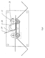
- the extractor has a main structure formed by the plates 1 and 1 'and a number of spacers 2 forming a frame.
- the envelope feed area includes the horizontal plate 3 mounted between the plates 1 and 1 '.
- the envelope 4 is supplied cut on three sides by a mechanism which is not part of the invention.
- the feeding device comprises the rollers 5 mounted on the shaft 6 and the rollers 7 mounted on the shaft 8.
- the rollers 5 are in contact with the rollers 7.
- the rollers 7 are set in motion by the motor 9 mounted at the end of the shaft 8 supporting the rollers 7.
- the extraction device comprises the rollers 10 mounted on the shaft 11 and the pairs of rollers 12 mounted on the shaft 13.
- the rollers 10 and 12 form a sector; that is to say that each roller 10 penetrates slightly in the pair of rollers 12 associated so that an envelope can pass between said rollers, slightly undulating.
- the rollers 10 are put in movement by the motor 9 via the belt pulley assembly 14-15 and 16.
- the pairs of rollers 12 are set in motion by the end-mounted motor 17 of the shaft 13.
- the sheet 18, mounted between the plates 1 and 1 ' serves to guide the envelope from the feed station to the extraction station.
- Prison 18 supports cell 19 which detects the passage of the envelope to its verticality.
- the device has a tray 20 for receiving envelopes emptied and a tray 21 for receiving the extracted pus. These two tanks are mounted between plates 1 and 1 '.
- the control means regulate and synchronize the motors as well as the detection organs. They include preferably a microprocessor.
- the device is in the starting position.
- the control means rotate the motor 9 clockwise.
- the rollers 5 and the rollers 7 rotate in the directions shown by the arrows 22 and 23.
- Synchronized by the belt pulley assembly 14-15 and 16, the rollers 10 rotate in the direction shown by arrow 24.
- the loaded envelope 4, previously cut on three sides by a mechanism not forming part of the invention, is taken into account by the rollers 5 and 7 by sliding on the sheet 3.
- Figure 4 shows the next step. Transporting the envelope 4 continues. The latter passes in front of cell 19.
- the control then rotates the motor 17 clockwise.
- the pairs of rollers 12 therefore rotate in the direction shown by arrow 25.
- the control unit stops the movement of said envelope by stopping the motors 9 and 17.
- Figure 5 shows the next step.
- the rotation of the motor 17 is reversed.
- the pairs of rollers 12 therefore rotate in the direction shown. by arrow 26.
- the upper part 27 of the envelope being in contact direct with the rollers 12, a loop 28 is formed from the hinge 29 of the envelope.
- the lower part 30 of the envelope remains stationary with its content since, due to the die formed by the rollers 12 and 10, it is in contact with the rollers 10 which are stopped.
- Figure 6 shows the next step. Pairs of rollers 12 continue their rotation in the direction shown by arrow 26; the loop 28 grows until the end of the part upper 27 is no longer in contact with the rollers 12.
- Figure 7 shows the next step.
- the control unit puts then in rotation the motors 9 and 17 so that the rollers 10 and 12 rotate in the directions shown by arrows 31 and 32.
- Figure 8 shows the final step. Control unit stops then suddenly the rotation of the rollers 10 and 12. Only a small portion of the upper part 27 of the envelope remains trapped in the die formed by the rollers 12 and 10. This sudden deceleration results in ejection of the contents 33 of the envelope to the reception tray 21. The operator checks visually that the contents of the envelope are well extracted. Two cases occur then present.
- Figure 9 shows the first case.
- the extracted mail does not does not include the references of the recipient, the operator recovers the envelope by pulling on the latter to read the address written on the envelope.
- Figure 10 shows the second case.
- the extracted mail includes the references of the recipient, the operator then launches the storage of the envelope 4.
- the control unit sets in motion the rollers 5-7-10 and 12 in the directions shown by arrows 34 and 35.
- the unfolded envelope then slides under the sheet 3 and is stored in the bin 20 for receiving empty envelopes.
Landscapes
- Sheets, Magazines, And Separation Thereof (AREA)
- Supplying Of Containers To The Packaging Station (AREA)
- Packaging Of Special Articles (AREA)
- Folding Of Thin Sheet-Like Materials, Special Discharging Devices, And Others (AREA)
- Controlling Sheets Or Webs (AREA)
Claims (8)
- Vorrichtung zum Herausnehmen des Inhalts aus einem an drei Seiten vorab geschnittenen Briefumschlag, mit einem Chassis (1, 1', 2, 2'); Mitteln (5, 7) zum Zuführen des vorab geschnittenen Briefumschlags (4), um ihn auf einem Weg fortzubewegen; Reibungsmitteln (10, 12), die auf dem Weg des Briefumschlags angeordnet sind, um ihn aufzufalten und seinen Inhalt herauszunehmen; Mitteln (21) zum Aufnehmen der herausgenommenen Inhalte; und Steuerungsmitteln, die den synchronisierten Betrieb der vorgenannten Mittel steuern,
dadurch gekennzeichnet, daß
die Reibungsmittel aus jeweils oberen und unteren Reibgliedern (10, 12) bestehen, die einen Reibungs-Mitnahmeraum für den Briefumschlag und seinen Inhalt bilden und ausgelegt sind, um ihn gemäß den folgenden aufeinanderfolgenden Schritten vorwärts oder rückwärts anzutreiben:a) die oberen Glieder (12) und unteren Glieder (10) treiben einen Briefumschlag (4) vorwärts an, dessen nicht geschnittene Seite hinten liegt,b) die unteren Glieder (10) treiben nicht an, und die oberen Glieder (12) treiben nach hinten an, wodurch sich die obere Lage (27) des Briefumschlags (4) wölbt und öffnet,c) die oberen Glieder (12) und unteren Glieder (10) treiben den geöffneten Briefumschlag (4) und seinen Inhalt (33) vorwärts an, bis der Inhalt (33) aus dem Mitnahmeraum freigegeben ist, der geöffnete Briefumschlag jedoch in ihm noch gehalten wird,d) die oberen Glieder (12) und unteren Glieder (10) halten den Antrieb schlagartig an, wodurch das Entweichen des Inhalts (33) ermöglicht wird, um in den Aufnahmemitteln (21) für die Inhalte aufgenommen zu werden. - Vorrichtung nach Anspruch 1, dadurch gekennzeichnet, daß die Aufnahmemittel (21) für die Inhalte so ausgelegt sind, daß sie eine unmittelbare visuelle Inspektion der Inhalte (33) gestatten.
- Vorrichtung nach einem der vorhergehenden Ansprüche, dadurch gekennzeichnet, daß die Reibungsmittel so ausgelegt sind, daß sie den folgenden zusätzlichen Schritt durchführen:e) die oberen Glieder (12) und unteren Glieder (10) treiben den leeren Briefumschlag (4) rückwärts an.
- Vorrichtung nach einem der vorhergehenden Ansprüche, dadurch gekennzeichnet, daß die Reibeglieder aus ineinandergreifenden Rollen (12, 10) bestehen.
- Vorrichtung nach einem der vorhergehenden Ansprüche, dadurch gekennzeichnet, daß die Zuführmittel aus gegenläufigen Rollen (5, 7) gebildet sind.
- Vorrichtung nach Anspruch 5 in Kombination mit Anspruch 4, dadurch gekennzeichnet, daß ein erster Motor (9) die Drehung der gegenläufigen Rollen (5, 7) und der unteren Reibrollen steuert, während ein zweiter Motor (17) die Drehung der oberen Reibrollen steuert.
- Vorrichtung nach einem der vorhergehenden Ansprüche, dadurch gekennzeichnet, daß sie stromauf von den Zuführmitteln ein oberes Zufuhrniveau (3) für vorab geschnittene volle Briefumschläge und ein unteres Aufnahmeniveau (20) für leere Briefumschläge aufweist, und daß die Zuführmittel (5, 7) bidirektional sind.
- Vorrichtung nach einem der vorhergehenden Ansprüche, dadurch gekennzeichnet, daß ein Sensor (19) den Durchlauf des Briefumschlags zwischen den Zuführmitteln (5, 7) und den Entnahmemitteln (12, 10) erfaßt.
Applications Claiming Priority (3)
| Application Number | Priority Date | Filing Date | Title |
|---|---|---|---|
| FR9605564A FR2748233B1 (fr) | 1996-05-03 | 1996-05-03 | Dispositif d'extraction du contenu d'une enveloppe |
| FR9605564 | 1996-05-03 | ||
| PCT/FR1997/000501 WO1997042039A1 (fr) | 1996-05-03 | 1997-03-21 | Dispositif d'extraction du contenu d'une enveloppe |
Publications (2)
| Publication Number | Publication Date |
|---|---|
| EP0897334A1 EP0897334A1 (de) | 1999-02-24 |
| EP0897334B1 true EP0897334B1 (de) | 1999-12-29 |
Family
ID=9491811
Family Applications (1)
| Application Number | Title | Priority Date | Filing Date |
|---|---|---|---|
| EP97915533A Expired - Lifetime EP0897334B1 (de) | 1996-05-03 | 1997-03-21 | Vorrichtung zum eintfernen des inhalts eines briefes |
Country Status (6)
| Country | Link |
|---|---|
| US (1) | US6092353A (de) |
| EP (1) | EP0897334B1 (de) |
| CA (1) | CA2253430C (de) |
| DE (1) | DE69701039T2 (de) |
| FR (1) | FR2748233B1 (de) |
| WO (1) | WO1997042039A1 (de) |
Families Citing this family (1)
| Publication number | Priority date | Publication date | Assignee | Title |
|---|---|---|---|---|
| US6725752B1 (en) * | 2001-10-22 | 2004-04-27 | Catawa, Inc. | Mail processing machine |
Family Cites Families (11)
| Publication number | Priority date | Publication date | Assignee | Title |
|---|---|---|---|---|
| FR1500045A (fr) * | 1966-06-14 | 1967-11-03 | Commissariat Energie Atomique | Procédé de séparation d'un produit plat d'avec son emballage de protection, et dispositif pour la mise en oeuvre du procédé |
| FR2045172A5 (en) * | 1969-06-12 | 1971-02-26 | Commissariat Energie Atomique | Stripping wrappers from flat articles |
| US3739543A (en) * | 1971-06-21 | 1973-06-19 | Automated Mail Syst Inc | Envelope opening apparatus and method |
| US4921388A (en) * | 1986-07-07 | 1990-05-01 | Systems Mailing Research, Inc. | Envelope opener and load separator |
| US4863037A (en) * | 1986-09-05 | 1989-09-05 | Opex Corporation | Apparatus for the automated processing of bulk mail and the like |
| US4866915A (en) * | 1988-12-12 | 1989-09-19 | Wise John D | Envelope contents removal |
| US5156515A (en) * | 1989-05-03 | 1992-10-20 | Omation Corporation | Machine for extracting contents from envelopes |
| NL9001238A (nl) * | 1990-05-30 | 1991-12-16 | Hadewe Bv | Inrichting en werkwijze voor het verwijderen van een inhoud uit een enveloppe. |
| NL9001237A (nl) * | 1990-05-30 | 1991-12-16 | Hadewe Bv | Werkwijze en inrichting voor het verwijderen van een inhoud uit een enveloppe. |
| FR2706146B1 (fr) * | 1993-06-07 | 1996-06-21 | Louis Chevalier | Dispositif de coupe rapide d'extraction et de tri du courrier contenu dans les enveloppes . |
| NL9401553A (nl) * | 1994-09-23 | 1996-05-01 | Hadewe Bv | Werkwijze en inrichting voor het openen van een enveloppe. |
-
1996
- 1996-05-03 FR FR9605564A patent/FR2748233B1/fr not_active Expired - Lifetime
-
1997
- 1997-03-21 CA CA002253430A patent/CA2253430C/fr not_active Expired - Fee Related
- 1997-03-21 WO PCT/FR1997/000501 patent/WO1997042039A1/fr not_active Ceased
- 1997-03-21 EP EP97915533A patent/EP0897334B1/de not_active Expired - Lifetime
- 1997-03-21 DE DE69701039T patent/DE69701039T2/de not_active Expired - Lifetime
- 1997-03-21 US US09/180,230 patent/US6092353A/en not_active Expired - Fee Related
Also Published As
| Publication number | Publication date |
|---|---|
| FR2748233A1 (fr) | 1997-11-07 |
| DE69701039D1 (de) | 2000-02-03 |
| CA2253430C (fr) | 2004-02-24 |
| DE69701039T2 (de) | 2000-08-03 |
| FR2748233B1 (fr) | 1998-07-17 |
| EP0897334A1 (de) | 1999-02-24 |
| WO1997042039A1 (fr) | 1997-11-13 |
| US6092353A (en) | 2000-07-25 |
| CA2253430A1 (fr) | 1997-11-13 |
Similar Documents
| Publication | Publication Date | Title |
|---|---|---|
| EP0275490B1 (de) | Ausgeber für flache Gegenstände | |
| EP0587883A1 (de) | Vorrichtung zur trennung von münzen, automatenmünzen oder dergleichen und selbsttätige bezahlapparate. | |
| EP0608161A1 (de) | Vorrichtung zum vorübergehenden Speichern von flachen Gegenständen | |
| EP0215469A1 (de) | Anlage zur Kennzeichnung von flachen Gegenständen, insbesondere Briefpost | |
| FR2621305A1 (fr) | Appareil de manipulation de feuilles | |
| FR2555917A1 (fr) | Machine de tri a debit ameliore | |
| EP0111432B1 (de) | Vorrichtung zur dynamischen Zwischenspeicherung flacher Gegenstände | |
| FR2907368A1 (fr) | Machine de faconnage d'ebauches de caisses en carton. | |
| EP0333596B1 (de) | Vorrichtung zum Stapeln von flachen Gegenständen, wie Briefe | |
| CA2253430C (fr) | Dispositif d'extraction du contenu d'une enveloppe | |
| FR2754599A1 (fr) | Appareil automatique de dosage immunologique | |
| FR2634729A1 (fr) | Dispositif de fermeture d'enveloppes | |
| EP0507661B1 (de) | Vorrichtung zum Herausnehmen flacher Gegenstände aus einem Stapel solcher Gegenstände, insbesondere für Briefumschläge | |
| EP0023462A1 (de) | Stauförderer | |
| FR2467144A1 (fr) | Procede et dispositif pour emballer des piles de papier dans des cartons prealablement formes | |
| EP0903248B1 (de) | Vorrichtung zur Neuorientierung von Briefumschlag | |
| CA2238001C (fr) | Systeme de depilage et d'ouverture d'enveloppes | |
| FR2623751A1 (fr) | Dispositif d'insertion de plis sous enveloppes | |
| EP0255684B1 (de) | Bogentransportvorrichtung | |
| FR2708488A1 (fr) | Dispositif injecteur d'objets dans une machine de tri postal. | |
| EP1462403B1 (de) | Vorrichtung zum Abtasten und Digitalisieren mit Durchlauf des Bogens mit dessen Vorderseite nach oben oder unten | |
| EP0523305A1 (de) | Vorrichtung mit Planetrollen zum Behandeln von Wertpapieren wie Banknoten | |
| EP1118556B1 (de) | Automatisches Verteilsystem für Gegenstände zum Kommissionieren einer oder mehrerer Bestellunguen | |
| FR2847888A1 (fr) | Dispositif pour le stockage et la distribution d'objets. | |
| FR2831530A1 (fr) | Dispositif pour la mise en pile d'objets plats tels que plis postaux |
Legal Events
| Date | Code | Title | Description |
|---|---|---|---|
| PUAI | Public reference made under article 153(3) epc to a published international application that has entered the european phase |
Free format text: ORIGINAL CODE: 0009012 |
|
| GRAG | Despatch of communication of intention to grant |
Free format text: ORIGINAL CODE: EPIDOS AGRA |
|
| 17P | Request for examination filed |
Effective date: 19981013 |
|
| AK | Designated contracting states |
Kind code of ref document: A1 Designated state(s): CH DE FR GB LI |
|
| 17Q | First examination report despatched |
Effective date: 19990212 |
|
| GRAG | Despatch of communication of intention to grant |
Free format text: ORIGINAL CODE: EPIDOS AGRA |
|
| GRAH | Despatch of communication of intention to grant a patent |
Free format text: ORIGINAL CODE: EPIDOS IGRA |
|
| GRAH | Despatch of communication of intention to grant a patent |
Free format text: ORIGINAL CODE: EPIDOS IGRA |
|
| GRAA | (expected) grant |
Free format text: ORIGINAL CODE: 0009210 |
|
| AK | Designated contracting states |
Kind code of ref document: B1 Designated state(s): CH DE FR GB LI |
|
| REG | Reference to a national code |
Ref country code: CH Ref legal event code: EP |
|
| REF | Corresponds to: |
Ref document number: 69701039 Country of ref document: DE Date of ref document: 20000203 |
|
| REG | Reference to a national code |
Ref country code: CH Ref legal event code: NV Representative=s name: ERNST ACKERMANN PATENTANWALT |
|
| GBT | Gb: translation of ep patent filed (gb section 77(6)(a)/1977) |
Effective date: 20000225 |
|
| PLBE | No opposition filed within time limit |
Free format text: ORIGINAL CODE: 0009261 |
|
| 26N | No opposition filed | ||
| REG | Reference to a national code |
Ref country code: GB Ref legal event code: IF02 |
|
| REG | Reference to a national code |
Ref country code: CH Ref legal event code: PFA Owner name: SECAP (GROUPE PITNEY BOWES) Free format text: SECAP#21, QUAI ALPHONSE LE GALLO#92100 BOULOGNE BILLANCOURT (FR) -TRANSFER TO- SECAP (GROUPE PITNEY BOWES)#21 QUAI ALPHONSE LE GALLO#92100 BOULOGNE BILLANCOURT (FR) |
|
| REG | Reference to a national code |
Ref country code: FR Ref legal event code: CD |
|
| REG | Reference to a national code |
Ref country code: CH Ref legal event code: PCAR Free format text: ERNST ACKERMANN PATENTANWALT;EGGHALDE;9231 EGG-FLAWIL (CH) |
|
| PGFP | Annual fee paid to national office [announced via postgrant information from national office to epo] |
Ref country code: CH Payment date: 20100325 Year of fee payment: 14 |
|
| PGFP | Annual fee paid to national office [announced via postgrant information from national office to epo] |
Ref country code: GB Payment date: 20100326 Year of fee payment: 14 |
|
| PGFP | Annual fee paid to national office [announced via postgrant information from national office to epo] |
Ref country code: DE Payment date: 20100329 Year of fee payment: 14 |
|
| PGFP | Annual fee paid to national office [announced via postgrant information from national office to epo] |
Ref country code: FR Payment date: 20110331 Year of fee payment: 15 |
|
| REG | Reference to a national code |
Ref country code: CH Ref legal event code: PL |
|
| GBPC | Gb: european patent ceased through non-payment of renewal fee |
Effective date: 20110321 |
|
| PG25 | Lapsed in a contracting state [announced via postgrant information from national office to epo] |
Ref country code: CH Free format text: LAPSE BECAUSE OF NON-PAYMENT OF DUE FEES Effective date: 20110331 Ref country code: DE Free format text: LAPSE BECAUSE OF NON-PAYMENT OF DUE FEES Effective date: 20111001 Ref country code: LI Free format text: LAPSE BECAUSE OF NON-PAYMENT OF DUE FEES Effective date: 20110331 |
|
| REG | Reference to a national code |
Ref country code: DE Ref legal event code: R119 Ref document number: 69701039 Country of ref document: DE Effective date: 20111001 |
|
| PG25 | Lapsed in a contracting state [announced via postgrant information from national office to epo] |
Ref country code: GB Free format text: LAPSE BECAUSE OF NON-PAYMENT OF DUE FEES Effective date: 20110321 |
|
| REG | Reference to a national code |
Ref country code: FR Ref legal event code: ST Effective date: 20121130 |
|
| PG25 | Lapsed in a contracting state [announced via postgrant information from national office to epo] |
Ref country code: FR Free format text: LAPSE BECAUSE OF NON-PAYMENT OF DUE FEES Effective date: 20120402 |