EP0023462A1 - Stauförderer - Google Patents
Stauförderer Download PDFInfo
- Publication number
- EP0023462A1 EP0023462A1 EP80401116A EP80401116A EP0023462A1 EP 0023462 A1 EP0023462 A1 EP 0023462A1 EP 80401116 A EP80401116 A EP 80401116A EP 80401116 A EP80401116 A EP 80401116A EP 0023462 A1 EP0023462 A1 EP 0023462A1
- Authority
- EP
- European Patent Office
- Prior art keywords
- housing
- rotor
- conveyor
- rollers
- carrier rollers
- Prior art date
- Legal status (The legal status is an assumption and is not a legal conclusion. Google has not performed a legal analysis and makes no representation as to the accuracy of the status listed.)
- Withdrawn
Links
Images

Classifications
-
- B—PERFORMING OPERATIONS; TRANSPORTING
- B65—CONVEYING; PACKING; STORING; HANDLING THIN OR FILAMENTARY MATERIAL
- B65G—TRANSPORT OR STORAGE DEVICES, e.g. CONVEYORS FOR LOADING OR TIPPING, SHOP CONVEYOR SYSTEMS OR PNEUMATIC TUBE CONVEYORS
- B65G47/00—Article or material-handling devices associated with conveyors; Methods employing such devices
- B65G47/22—Devices influencing the relative position or the attitude of articles during transit by conveyors
- B65G47/26—Devices influencing the relative position or the attitude of articles during transit by conveyors arranging the articles, e.g. varying spacing between individual articles
- B65G47/261—Accumulating articles
Definitions
- the present invention relates to an accumulator conveyor intended for the mechanical handling of isolated loads.
- the conveyor can be operated step by step by loading an upstream conveyor while a downstream conveyor is emptying, or using as many conveyor modules as there are charges to accumulate.
- One of these known devices comprising flat cams for applying the drive element against the carrier rollers, leads to very noisy operation because, with each rotation of the cams, the drive element rises and falls and hits the carrier rollers.
- the drive belt of the carrier rollers rubs on the cam flats, which consumes energy, wears out the band and increases the force necessary to re-engage the mechanism.
- the aim of the present invention is therefore to propose a disengageable accumulator conveyor, on which the pressure to be exerted on the detector to detect the presence of charges is independent of the pressure exerted by the clutch-disengaging device of the drive element, and which does not have the various aforementioned drawbacks, namely a flutter of the noise-generating drive element, and a friction said drive element on the clutch cams, generator of wear and loss of energy.
- the accumulator conveyor for isolated loads comprises a chassis, a sole with carrying rollers on which the loads rest and move, at least one endless driving belt moving continuously under the carrying rollers and ensuring the rotation of these by friction, pressure rotors with eccentric pivot axis supporting said drive belt and intended to apply it against the carrying rollers, and detectors of presence of loads distributed along the sole of the conveyor the carrying rollers, each pressure rotor of said conveyor according to the invention comprising a generally cylindrical housing roughly mounted pivoting about an eccentric axis and at least one pressure roller or pressure cam mounted rotating inside the housing and centered relative to its periphery, the cylindrical wall of said housing comprising two windows angularly offset allowing the peripheral surface of the roller to protrude , said windows all being located on the same side relative to the diametral plane of the housing which passes through the pivot axis of the rotor.
- each rotor housing has two stop pins located at different distances from the pivot axis of the rotor, a control strip.
- a control strip provided with notches being slidably mounted on the chassis of the conveyor, along the face of the case carrying the stop fingers of each rotor, said strips being each connected to a detector by a control linkage which ensures their movement parallel to said faces of the case.
- the roller conveyor 1 comprises a conventional chassis 2 constituted in a manner known per se by an assembly of metal beams, a carrier roller sole 3 arranged parallel to each other and able to rotate freely in bearings carried by the side rails of the chassis 2, a longitudinal central beam 4 fixed on crosspieces 5 of the chassis 2 and supporting rotors 6 d application of drive belts 7, said strip being a continuous strip permanently driven by a motor device not shown and which can be applied by said rotors 6 under the rollers 3 of the sole of the conveyor so as to drive them in rotation .
- the band application rotors 6 are pivotally mounted around eccentric axes fixed on the central beam 4 parallel to the axes of rotation of the support rollers 3.
- the lower strand of the drive band 7 is supported by rollers 8 which l prevent floating.
- load presence detectors 9 are provided, constituted either by a simple pad, or by a roller mounted at the end of a lever 10, the tilting of which causes the displacement of a whole linkage making it possible to remotely control the lowering of the drive belt 7 out of contact with the carrier rollers 3 or, on the contrary, its application under said rollers so as to ensure their friction drive.
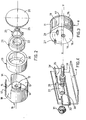
- Each application or strip pressure rotor comprises a cylindrical housing 11 provided with a central hub 12 concentric with the external wall 13 of said housing.
- the hub 12 has an eccentric bore 14 which passes right through it parallel to the axis of said hub.
- the generally cylindrical wall of roughly peripheral shape 13 of the housing is notched in two spaced locations so as to form two windows 15 and 16 separated by a portion of wall 17.
- This wall 13 has, in the vicinity of window 15, an extra thickness outer, that is to say that the inner surface of this wall is a cylinder of revolution, while its outer surface is, or else a cylinder of revolution eccentric so that the distance between the two cylindrical surfaces is maximum in the vicinity from that of the edges of the window 15 which is furthest from the window 16, or else a surface of more complicated shape but leading to an extra thickness in the same place.
- the housing 11 has a bottom 18 in which the hub 12 is placed and it is open on the face opposite to said bottom so as to be able to receive a roller 19 comprising a bore 20 inside which is housed a ball bearing or the like. 21, the inner ring 22 of which is fitted onto the hub 12 and retained thereon by a clip 23.
- the bearing 21 and the roller 19 are fitted inside the housing 11, the latter is mounted on its pivot axis 24 (see fig. 4) on which it is retained by a clip 25 (fig. 2) and the box is closed by a cover 26.
- the rotor 6 thus assembled can pivot around its pivot axis 24 which passes through the hub 12 inside the eccentric bore 14.
- This axis 24 (FIG. 4) had a threaded tail 29 which serves to fix it rigidly through a hole 30 drilled in the wing of the central beam 4, the connection being effected by means of a nut 31 blocked on said threaded tail 29.
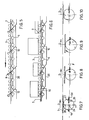
- a control strip is applied 32 capable of sliding longitudinally along said vertical wing and parallel to the bottom 18 of the rotors 6.
- the control strip 32 has a slot 33 which is crossed by the axis 24 of the rotors 6, said strip further comprising a wing folded over the bracket 34 in which is formed a notch 35 of width greater than the diameter of the stop pins 27 and 28 of the rotors 6.
- each load comes to press on a detector 9, causing the levers 10 associated with these detectors to pivot, which has the effect of moving the linkage 36 backwards, which makes slide the control strip 32 along the vertical wing of the central beam 4 of the conveyor, said strip 32 having either its square wing 34 or the notch 35 on the path of the stop pins 27 and 28 of the rotors 6.
- the housing 11 of the rotor which is pivotally mounted about its eccentric axis 24 is retained by the square wing 34 of the strip 32 on which its stop pin 27 abuts.
- the drive belt 7 rests on the roller 19 which projects beyond the housing 11 through the window 16 thereof.
- the strip 7 is driven in the direction of arrow D and the roller 19 rolls without friction along said strip, which largely eliminates wear thereof.
- the latter is pushed in and rotates its lever arm 10 which pushes back the control linkage 36, which slides the strip 32 along the central beam 4 and positions the notch 35 of the said strip on the circular path of the pin 27 of the rotor 6.
- the strip 32 therefore lets the said pin escape and the rotor housing rocks around the axis 24 on the combined effect of its own weight and the weight of the strip 7 which rests on the roller 19.
- the rotation of the housing 11 is interrupted when the second pin 28 abuts against the wing 34 of the strip 32, due to the fact that said pin moves on a circumference different from that of the pin 28.
- Figure 8 the upper level of the rotor, as well as the drive belt 7, has collapsed relative to the lower plane of the carrier rollers 3 so that said rollers are no longer entrained - born by the drive band 7 which is no longer in contact with their lower part. There is then declutching and accumulation of the isolated loads on the conveyor.
- a displacement of the strip 32 positions the notch 35 on the path of the second pin 28 for retaining the stator housing, so that said pin 28 can escape and the stator continues to tilt under its own weight and under the weight of the strip 7 which rests on it (Figure 9).
- the strip 7 no longer rests on the pressure roller 19 but comes to rest on the peripheral wall of the housing 11 itself and rotates clockwise the rotor 6 by rubbing against the periphery of said housing 11.
- the rotor then performs three-quarters of a turn and rises so that it again occupies the position it had in FIG.
- lever arms 10 of the detectors are returned to the high position by a return spring, not shown.
- the detection and clutch-declutching functions are dissociated, the first function being used to control the power taken from the drive belt to perform the second function. There is thus a power amplification making it possible to obtain a high maximum / minimum weight ratio.
- the drive belt 7 rolls on the roller or cam pressure 19 without rubbing on it, the pressure cam being in continuous rotation in the high position as in the low position.
- This device is a power draw device controlled by a low level signal which allows any organ to be raised or lowered.
- a train of three rotors 6 can be replaced by an assembly formed by a rotor and a number of idle rollers, these rollers being able to be lowered or raised by another linkage which is itself even controlled by the rotation of the rotor which has been preserved.
- the power captured by the rotor in its rotational movement can also be used for other uses, for example to raise or lower a stopper.
- the device and in particular the mode of energy extraction via the rotation of the rotor, can be used not only in handling, but in all areas where a strong amplification of power, combined with a limited displacement, is necessary.
Landscapes
- Engineering & Computer Science (AREA)
- Mechanical Engineering (AREA)
- Rollers For Roller Conveyors For Transfer (AREA)
- Structure Of Belt Conveyors (AREA)
Applications Claiming Priority (2)
| Application Number | Priority Date | Filing Date | Title |
|---|---|---|---|
| FR7919607A FR2462365A1 (fr) | 1979-07-30 | 1979-07-30 | Transporteur accumulateur |
| FR7919607 | 1979-07-30 |
Publications (1)
| Publication Number | Publication Date |
|---|---|
| EP0023462A1 true EP0023462A1 (de) | 1981-02-04 |
Family
ID=9228449
Family Applications (1)
| Application Number | Title | Priority Date | Filing Date |
|---|---|---|---|
| EP80401116A Withdrawn EP0023462A1 (de) | 1979-07-30 | 1980-07-28 | Stauförderer |
Country Status (8)
| Country | Link |
|---|---|
| US (1) | US4345684A (de) |
| EP (1) | EP0023462A1 (de) |
| JP (1) | JPS5643113A (de) |
| BR (1) | BR8004747A (de) |
| CA (1) | CA1141693A (de) |
| DK (1) | DK326480A (de) |
| ES (1) | ES8105662A1 (de) |
| FR (1) | FR2462365A1 (de) |
Cited By (3)
| Publication number | Priority date | Publication date | Assignee | Title |
|---|---|---|---|---|
| GB2156299A (en) * | 1984-03-16 | 1985-10-09 | Dexion Comino Int Ltd | Improvements relating to accumulation conveyors |
| US4958723A (en) * | 1984-09-17 | 1990-09-25 | Mannesmann Ag | Roller track |
| US5042644A (en) * | 1982-01-27 | 1991-08-27 | Ermanco Incorporated | Zero pressure accumulation conveyor and trigger assembly |
Families Citing this family (10)
| Publication number | Priority date | Publication date | Assignee | Title |
|---|---|---|---|---|
| JPS59223609A (ja) * | 1983-05-23 | 1984-12-15 | ハリ−・メイジヤ− | 品物を搬送するためのロ−ラコンベヤ |
| US4505381A (en) * | 1983-05-23 | 1985-03-19 | Harry Major Machine And Tool Co. | Conveyor roller |
| DE3434092C2 (de) * | 1984-09-17 | 1986-10-23 | Mannesmann AG, 4000 Düsseldorf | Staurollenbahn |
| US4753339A (en) * | 1987-05-20 | 1988-06-28 | The Buschman Company | Accumulating conveyor of the low pressure type |
| JPH0757912B2 (ja) * | 1990-07-04 | 1995-06-21 | 工業技術院長 | アルミニウムのエッチング法 |
| DE10020608A1 (de) * | 2000-04-27 | 2001-10-31 | Dynamic Systems Engineering B | Lager- und/oder Transportvorrichtung für Stückgüter |
| US20060260913A1 (en) * | 2005-05-20 | 2006-11-23 | Wolf Stephen C | Retractable multiple-stage trailer loader/unloader apparatus |
| US7364035B2 (en) * | 2005-05-25 | 2008-04-29 | Dematic Corp. | Airless accumulation conveyor |
| ES2641716T3 (es) * | 2011-02-18 | 2017-11-13 | Laitram, Llc | Transportador de rodillos de diámetro pequeño |
| US10899547B1 (en) * | 2019-11-21 | 2021-01-26 | Intelligrated Headquarters, Llc | Coupling block on a conveyor system |
Citations (2)
| Publication number | Priority date | Publication date | Assignee | Title |
|---|---|---|---|---|
| FR1225981A (fr) * | 1959-02-25 | 1960-07-06 | Rapids Standard Company | Transporteurs à accumulation des objets transportés |
| FR1437310A (fr) * | 1965-06-24 | 1966-04-29 | Rapids Standard Company | Transporteur à commande d'avance automatique d'articles |
Family Cites Families (4)
| Publication number | Priority date | Publication date | Assignee | Title |
|---|---|---|---|---|
| US3253097A (en) * | 1963-09-19 | 1966-05-24 | Bell Telephone Labor Inc | Strong make or break reed switch |
| GB1442687A (en) * | 1973-04-09 | 1976-07-14 | Ind Treuhand Ag | Conveying apparatus |
| US3854576A (en) * | 1973-06-27 | 1974-12-17 | Rapistan Inc | Eccentric wheel accumulators |
| US3958684A (en) * | 1974-08-07 | 1976-05-25 | A W & H Manufacturing Co., Inc. | Accumulating conveyor |
-
1979
- 1979-07-30 FR FR7919607A patent/FR2462365A1/fr active Granted
-
1980
- 1980-07-28 US US06/173,126 patent/US4345684A/en not_active Expired - Lifetime
- 1980-07-28 EP EP80401116A patent/EP0023462A1/de not_active Withdrawn
- 1980-07-29 ES ES493799A patent/ES8105662A1/es not_active Expired
- 1980-07-29 CA CA000357249A patent/CA1141693A/en not_active Expired
- 1980-07-29 DK DK326480A patent/DK326480A/da not_active Application Discontinuation
- 1980-07-29 JP JP10494180A patent/JPS5643113A/ja active Pending
- 1980-07-29 BR BR8004747A patent/BR8004747A/pt unknown
Patent Citations (2)
| Publication number | Priority date | Publication date | Assignee | Title |
|---|---|---|---|---|
| FR1225981A (fr) * | 1959-02-25 | 1960-07-06 | Rapids Standard Company | Transporteurs à accumulation des objets transportés |
| FR1437310A (fr) * | 1965-06-24 | 1966-04-29 | Rapids Standard Company | Transporteur à commande d'avance automatique d'articles |
Cited By (3)
| Publication number | Priority date | Publication date | Assignee | Title |
|---|---|---|---|---|
| US5042644A (en) * | 1982-01-27 | 1991-08-27 | Ermanco Incorporated | Zero pressure accumulation conveyor and trigger assembly |
| GB2156299A (en) * | 1984-03-16 | 1985-10-09 | Dexion Comino Int Ltd | Improvements relating to accumulation conveyors |
| US4958723A (en) * | 1984-09-17 | 1990-09-25 | Mannesmann Ag | Roller track |
Also Published As
| Publication number | Publication date |
|---|---|
| CA1141693A (en) | 1983-02-22 |
| FR2462365B1 (de) | 1982-05-21 |
| JPS5643113A (en) | 1981-04-21 |
| ES493799A0 (es) | 1981-06-01 |
| ES8105662A1 (es) | 1981-06-01 |
| DK326480A (da) | 1981-01-31 |
| FR2462365A1 (fr) | 1981-02-13 |
| BR8004747A (pt) | 1981-02-10 |
| US4345684A (en) | 1982-08-24 |
Similar Documents
| Publication | Publication Date | Title |
|---|---|---|
| EP0023462A1 (de) | Stauförderer | |
| FR2601626A1 (fr) | Imprimante, cassette de ruban pour imprimante et procede de montage de cassette | |
| EP3283857B1 (de) | Vorrichtung zum transport von objekten und mit solchen transportvorrichtungen ausgestattete förderungs- und wiegevorrichtung | |
| CH638155A5 (fr) | Appareil de distribution de feuilles. | |
| EP0021398A1 (de) | Wendevorrichtung für Bögen | |
| WO1999032380A1 (fr) | Dispositif de transfert et convoyeur equipe d'un tel dispositif | |
| WO1989003798A1 (fr) | Procede et appareil pour distribuer automatiquement des objets | |
| CA2670672C (fr) | Sabot de calage d'une roue et installation de calage motorisee | |
| EP0333596B1 (de) | Vorrichtung zum Stapeln von flachen Gegenständen, wie Briefe | |
| EP0352686B1 (de) | Vorrichtung zum Öffnen und Füllen von Briefumschlägen | |
| FR2960866A1 (fr) | Receptacle de convoyage basculant lateralement et a fleau transversal et dispositif de convoyage equipe de tels receptacles | |
| EP0638496A1 (de) | Vorrichtung und Verfahren zum Einführen von blattformigem Material in eine Maschine | |
| WO2002028752A1 (fr) | Procede et dispositif pour reguler l'espacement et la vitesse d'objets cheminant de facon aleatoire | |
| EP1401746A2 (de) | Vorrichtung zum zuführen von teilen zu einer maschine | |
| EP3478377B1 (de) | Fortbewegungsvorrichtung mit rollen | |
| FR2511654A1 (fr) | Systeme transporteur pour objets en forme de tiges tels que des cigarettes ou des tiges filtrantes pour cigarettes | |
| FR2584648A1 (fr) | Dispositif de guidage notamment pour engin du type robot | |
| FR2708488A1 (fr) | Dispositif injecteur d'objets dans une machine de tri postal. | |
| EP0523305B1 (de) | Vorrichtung mit Planetrollen zum Behandeln von Wertpapieren wie Banknoten | |
| EP1462403B1 (de) | Vorrichtung zum Abtasten und Digitalisieren mit Durchlauf des Bogens mit dessen Vorderseite nach oben oder unten | |
| WO1993002953A1 (fr) | Machine de traitement d'objets plats | |
| FR3020352A1 (fr) | Convoyeur a bande et dispositif de transport de produits comprenant au moins deux convoyeurs du type precite | |
| FR2756496A1 (fr) | Appareil de grattage d'un support d'informations masquees | |
| FR2766805A1 (fr) | Dispositif d'alimentation de feuilles | |
| FR2536340A1 (fr) | Dispositif pour transporter une feuille de papier ou l'analogue destinee a etre imprimee dans une imprimante |
Legal Events
| Date | Code | Title | Description |
|---|---|---|---|
| PUAI | Public reference made under article 153(3) epc to a published international application that has entered the european phase |
Free format text: ORIGINAL CODE: 0009012 |
|
| AK | Designated contracting states |
Designated state(s): AT BE CH DE GB IT LU NL SE |
|
| 17P | Request for examination filed |
Effective date: 19810406 |
|
| STAA | Information on the status of an ep patent application or granted ep patent |
Free format text: STATUS: THE APPLICATION IS DEEMED TO BE WITHDRAWN |
|
| 18D | Application deemed to be withdrawn |
Effective date: 19830518 |
|
| RIN1 | Information on inventor provided before grant (corrected) |
Inventor name: ROLLAND, GUY |