EP0897121A2 - Dispositif pour localiser l'entrée d'objets dans un domaine spatial surveillé - Google Patents
Dispositif pour localiser l'entrée d'objets dans un domaine spatial surveillé Download PDFInfo
- Publication number
- EP0897121A2 EP0897121A2 EP98114496A EP98114496A EP0897121A2 EP 0897121 A2 EP0897121 A2 EP 0897121A2 EP 98114496 A EP98114496 A EP 98114496A EP 98114496 A EP98114496 A EP 98114496A EP 0897121 A2 EP0897121 A2 EP 0897121A2
- Authority
- EP
- European Patent Office
- Prior art keywords
- window
- pollution measurement
- deflecting mirror
- axis
- rotation
- Prior art date
- Legal status (The legal status is an assumption and is not a legal conclusion. Google has not performed a legal analysis and makes no representation as to the accuracy of the status listed.)
- Granted
Links
Images

Classifications
-
- G—PHYSICS
- G01—MEASURING; TESTING
- G01S—RADIO DIRECTION-FINDING; RADIO NAVIGATION; DETERMINING DISTANCE OR VELOCITY BY USE OF RADIO WAVES; LOCATING OR PRESENCE-DETECTING BY USE OF THE REFLECTION OR RERADIATION OF RADIO WAVES; ANALOGOUS ARRANGEMENTS USING OTHER WAVES
- G01S7/00—Details of systems according to groups G01S13/00, G01S15/00, G01S17/00
- G01S7/48—Details of systems according to groups G01S13/00, G01S15/00, G01S17/00 of systems according to group G01S17/00
- G01S7/481—Constructional features, e.g. arrangements of optical elements
- G01S7/4817—Constructional features, e.g. arrangements of optical elements relating to scanning
-
- G—PHYSICS
- G01—MEASURING; TESTING
- G01S—RADIO DIRECTION-FINDING; RADIO NAVIGATION; DETERMINING DISTANCE OR VELOCITY BY USE OF RADIO WAVES; LOCATING OR PRESENCE-DETECTING BY USE OF THE REFLECTION OR RERADIATION OF RADIO WAVES; ANALOGOUS ARRANGEMENTS USING OTHER WAVES
- G01S7/00—Details of systems according to groups G01S13/00, G01S15/00, G01S17/00
- G01S7/48—Details of systems according to groups G01S13/00, G01S15/00, G01S17/00 of systems according to group G01S17/00
- G01S7/481—Constructional features, e.g. arrangements of optical elements
- G01S7/4811—Constructional features, e.g. arrangements of optical elements common to transmitter and receiver
-
- G—PHYSICS
- G01—MEASURING; TESTING
- G01S—RADIO DIRECTION-FINDING; RADIO NAVIGATION; DETERMINING DISTANCE OR VELOCITY BY USE OF RADIO WAVES; LOCATING OR PRESENCE-DETECTING BY USE OF THE REFLECTION OR RERADIATION OF RADIO WAVES; ANALOGOUS ARRANGEMENTS USING OTHER WAVES
- G01S7/00—Details of systems according to groups G01S13/00, G01S15/00, G01S17/00
- G01S7/48—Details of systems according to groups G01S13/00, G01S15/00, G01S17/00 of systems according to group G01S17/00
- G01S7/497—Means for monitoring or calibrating
-
- G—PHYSICS
- G01—MEASURING; TESTING
- G01S—RADIO DIRECTION-FINDING; RADIO NAVIGATION; DETERMINING DISTANCE OR VELOCITY BY USE OF RADIO WAVES; LOCATING OR PRESENCE-DETECTING BY USE OF THE REFLECTION OR RERADIATION OF RADIO WAVES; ANALOGOUS ARRANGEMENTS USING OTHER WAVES
- G01S17/00—Systems using the reflection or reradiation of electromagnetic waves other than radio waves, e.g. lidar systems
- G01S17/02—Systems using the reflection of electromagnetic waves other than radio waves
- G01S17/06—Systems determining position data of a target
- G01S17/42—Simultaneous measurement of distance and other co-ordinates
-
- G—PHYSICS
- G01—MEASURING; TESTING
- G01S—RADIO DIRECTION-FINDING; RADIO NAVIGATION; DETERMINING DISTANCE OR VELOCITY BY USE OF RADIO WAVES; LOCATING OR PRESENCE-DETECTING BY USE OF THE REFLECTION OR RERADIATION OF RADIO WAVES; ANALOGOUS ARRANGEMENTS USING OTHER WAVES
- G01S7/00—Details of systems according to groups G01S13/00, G01S15/00, G01S17/00
- G01S7/48—Details of systems according to groups G01S13/00, G01S15/00, G01S17/00 of systems according to group G01S17/00
- G01S7/497—Means for monitoring or calibrating
- G01S2007/4975—Means for monitoring or calibrating of sensor obstruction by, e.g. dirt- or ice-coating, e.g. by reflection measurement on front-screen
-
- G—PHYSICS
- G01—MEASURING; TESTING
- G01S—RADIO DIRECTION-FINDING; RADIO NAVIGATION; DETERMINING DISTANCE OR VELOCITY BY USE OF RADIO WAVES; LOCATING OR PRESENCE-DETECTING BY USE OF THE REFLECTION OR RERADIATION OF RADIO WAVES; ANALOGOUS ARRANGEMENTS USING OTHER WAVES
- G01S7/00—Details of systems according to groups G01S13/00, G01S15/00, G01S17/00
- G01S7/02—Details of systems according to groups G01S13/00, G01S15/00, G01S17/00 of systems according to group G01S13/00
- G01S7/40—Means for monitoring or calibrating
- G01S7/4052—Means for monitoring or calibrating by simulation of echoes
- G01S7/406—Means for monitoring or calibrating by simulation of echoes using internally generated reference signals, e.g. via delay line, via RF or IF signal injection or via integrated reference reflector or transponder
-
- G—PHYSICS
- G01—MEASURING; TESTING
- G01S—RADIO DIRECTION-FINDING; RADIO NAVIGATION; DETERMINING DISTANCE OR VELOCITY BY USE OF RADIO WAVES; LOCATING OR PRESENCE-DETECTING BY USE OF THE REFLECTION OR RERADIATION OF RADIO WAVES; ANALOGOUS ARRANGEMENTS USING OTHER WAVES
- G01S7/00—Details of systems according to groups G01S13/00, G01S15/00, G01S17/00
- G01S7/48—Details of systems according to groups G01S13/00, G01S15/00, G01S17/00 of systems according to group G01S17/00
- G01S7/481—Constructional features, e.g. arrangements of optical elements
- G01S7/4811—Constructional features, e.g. arrangements of optical elements common to transmitter and receiver
- G01S7/4813—Housing arrangements
Definitions
- the invention relates to a device for locating in one objects to be monitored for intruding objects according to the generic term of claim 1.
- Such a device is known from DE-A-4 340 756, at which is a housing with an extending over an angle of 180 ° Window is provided, which is inclined to the emitted optical radiation provided and provided with an underside, angled edge area is. Light barriers are arranged along the circumference of the window, whose radiation passes through the window and its edge area, so determine any contamination. The one from the deflector Radiation deflected at a variable angle is transmitted partly reflected at the two interfaces of the window.
- Another device for locating in to be monitored Objects penetrating the spatial area are known from DE-A-4 315 077, in which an optical deflection device rotatable about an axis consists of two mutually perpendicular mirrors is provided, with a in a beam arranged at an angle of 45 ° to the axis of rotation to one area to be monitored while the other, arranged perpendicular to the above-mentioned mirror from the to monitoring area reflected beam of rays via a concave mirror throws on a receiver located in its focal point. If this device is housed in a windowed casing, the same problems occur that have already been discussed above were.
- DE-A-19 530 281 discloses an optical detection device of obstacles known from vehicles, one in a housing arranged scanner comprises, the housing with a curved Windscreen for closing against weather influences according to a Headlight front window is provided.
- the object of the invention is a device according to the preamble of claim 1, in which the impact of the window reflected radiation on the receiver as well as the occurrence an astigmatic effect with regard to the emitted beam is avoided.
- a window in the form of a spherical section whose center is the intersection of the axis of rotation with the optical Axes of the incoming and outgoing beam of rays interfaces of the window which are equidistant from this intersection, so that reflected light of the emerging bundle of rays in itself itself is reflected back, the optical effect of these interfaces with respect to an emitted beam in each section plane through the center of the sphere is exactly the same, making no astigmatic Effect can occur.
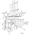
- the device shown in Fig. 1 comprises a housing 1, provide a window 2 to a room area to be monitored is. There is a transmitter 3 and a within the housing 1 Receiver 4 for optical radiation, in particular (pulsed) laser radiation. A beam of rays 5 emitted by the transmitter 3 is transmitted via a Collimator optics 6 and two plan adjustment and deflection mirrors inclined by 45 ° 7 thrown onto an optical deflection device 8. The deflection device 8 is rotatable about an axis of rotation 10 via a motor 9.
- the deflection device 8 comprises a transmission deflecting mirror 11 and a reception deflection mirror which is fixed and vertically mounted in relation to this 12.
- the plan transmit and receive deflecting mirrors 11, 12 are both arranged at an angle of 45 ° to the axis of rotation 10, wherein the receiving deflection mirror 12 has a central recess 13 in which the transmission deflecting mirror 11 is arranged.
- Transmitting and receiving deflecting mirrors 11, 12 are on a carrier 14 attached, the foot 15 is coupled to a motor 9 to the deflection device 8 to rotate about the axis of rotation 10.
- the beam 5 is through the Window 2 reflects and sweeps over the area to be monitored due to the continuous rotation of the deflection device 8 the area to be monitored.
- Beam 16 enters the housing 1 through the window 2 and falls on a reception deflecting mirror 12, from which it is directed to a reception collimator 17 falls, the beam 16 onto the receiver 4th bundles the presence or absence of an object in the area to be monitored Area.
- the window 2 is elongated, of constant height and Strength and leads, for example, to a scanning area that extends over extends approximately 180 ° perpendicular to the axis of rotation 10.
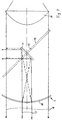
- the scanning range of the emitted beam 5 is through a central portion 18 of the Window 2 limited in the form of a spherical section, the center of which the intersection of the axis of rotation 10 with the optical axes of the one and emerging beam 5, 16.
- the middle section 18 of the Window 2 a revolving, in the direction of the convexity of the window 2, i.e. outwardly extending edge region 19 ', 19' ', which in a peripheral flange 20 passes. This enables an effective measurement of contamination of the window 2 as described below.
- Pollution measurement transmitter 23 of the pollution measurement transmitter assembly 22 can also be annular along the corresponding Edge region 19 '' of the window 2 can be arranged, these and the associated receivers 21 are operated in multiplex mode.
- 23 diodes used have one Beam angle of about 20 ° (full width at half maximum).
- the receivers 21 are connected in parallel with the receiver 21 arranged next to each other, so that two active receiving systems K1, K2 (see FIG. 2) available.
- the pollution measurement transmitters 23 are time-division multiplexed operated, so that "radiation channels" form between pollution measurement transmitter 23 and receiver 21, which penetrate the window 2 twice, with contamination in one or both penetrated zones to a signal attenuation on the corresponding Receiver 21 leads.
- the radiation angle of the pollution measurement transmitter 23 and the Distance between two receivers 21 connected in parallel is expedient chosen so that no pollution measurement transmitter control radiation is applied to two receivers 21 of a receiving system can.
- pollution measurement transmitters 23 can also be a blanked out from the transmitted beam 5 Pollution measurement beam or one from a single pollution measurement transmitter correspondingly emitted pollution measurement beam use that over an appropriate deflecting mirror that is rotates with the deflection device 8, for example, about the axis of rotation 10 rotating the middle section 18 at least once and at least one Edge area 19 ', 19' 'is detected by corresponding receivers 21 becomes.
- a uniformly backscattering surface can be arranged in the housing 1 that the pollution measurement beam reflected by the deflecting mirror below variable angle hits.
Landscapes
- Engineering & Computer Science (AREA)
- Computer Networks & Wireless Communication (AREA)
- Physics & Mathematics (AREA)
- General Physics & Mathematics (AREA)
- Radar, Positioning & Navigation (AREA)
- Remote Sensing (AREA)
- Optical Radar Systems And Details Thereof (AREA)
- Investigating Or Analysing Materials By Optical Means (AREA)
- Burglar Alarm Systems (AREA)
Applications Claiming Priority (3)
| Application Number | Priority Date | Filing Date | Title |
|---|---|---|---|
| DE19735037 | 1997-08-13 | ||
| DE19735037A DE19735037C2 (de) | 1997-08-13 | 1997-08-13 | Vorrichtung zum Orten von in einen zu überwachenden Raumbereich eindringenden Objekten |
| US09/135,069 US6153878A (en) | 1997-08-13 | 1998-08-17 | Device for locating objects penetrating into a region of space to be monitored |
Publications (3)
| Publication Number | Publication Date |
|---|---|
| EP0897121A2 true EP0897121A2 (fr) | 1999-02-17 |
| EP0897121A3 EP0897121A3 (fr) | 2000-01-05 |
| EP0897121B1 EP0897121B1 (fr) | 2004-11-10 |
Family
ID=26039094
Family Applications (1)
| Application Number | Title | Priority Date | Filing Date |
|---|---|---|---|
| EP98114496A Expired - Lifetime EP0897121B1 (fr) | 1997-08-13 | 1998-08-01 | Dispositif pour localiser l'entrée d'objets dans un domaine spatial surveillé |
Country Status (3)
| Country | Link |
|---|---|
| US (1) | US6153878A (fr) |
| EP (1) | EP0897121B1 (fr) |
| DE (1) | DE19735037C2 (fr) |
Cited By (3)
| Publication number | Priority date | Publication date | Assignee | Title |
|---|---|---|---|---|
| EP1148345A1 (fr) * | 2000-04-19 | 2001-10-24 | Schmersal-EOT GmbH & Co. KG | Dispositif pour localiser l'entrée d'objets dans un domaine spatial surveillé |
| EP1666913A3 (fr) * | 2004-11-19 | 2007-07-18 | Leuze electronic GmbH + Co KG | Capteur optique |
| EP1939650A3 (fr) * | 2006-12-28 | 2009-01-28 | Hokuyo Automatic Co., Ltd. | Dispositif de détection de contamination de fenêtre optique pour appareil optique |
Families Citing this family (21)
| Publication number | Priority date | Publication date | Assignee | Title |
|---|---|---|---|---|
| WO2001043117A1 (fr) * | 1999-12-07 | 2001-06-14 | Moshe Klotz | Dispositif desaxe de detection de lumiere |
| DE10114362C2 (de) * | 2001-03-22 | 2003-12-24 | Martin Spies | Laserscan-System für Entfernungsmessung |
| DE10230397A1 (de) | 2002-07-05 | 2004-01-15 | Sick Ag | Laserabtastvorrichtung |
| DE10331529A1 (de) * | 2003-07-11 | 2005-01-27 | Ibeo Automobile Sensor Gmbh | Optoelektronische Erfassungseinrichtung |
| DE102005043931A1 (de) * | 2005-09-15 | 2007-03-29 | Fraunhofer-Gesellschaft zur Förderung der angewandten Forschung e.V. | Laserscanner |
| DE102005055572B4 (de) * | 2005-11-19 | 2007-08-02 | Ingenieurbüro Spies GbR (vertretungsberechtigte Gesellschafter: Hans Spies, Martin Spies, 86558 Hohenwart) | Abtastender optischer Abstandssensor |
| USRE46672E1 (en) | 2006-07-13 | 2018-01-16 | Velodyne Lidar, Inc. | High definition LiDAR system |
| US7697120B2 (en) * | 2006-11-27 | 2010-04-13 | Riegl Laser Measurement Systems Gmbh | Scanning apparatus |
| EP2381268B1 (fr) * | 2010-04-22 | 2012-06-27 | Sick AG | Scanner laser de sécurité |
| DE102016100322B4 (de) * | 2016-01-11 | 2021-08-19 | Sick Ag | Optoelektronischer Sensor |
| US10627490B2 (en) | 2016-01-31 | 2020-04-21 | Velodyne Lidar, Inc. | Multiple pulse, LIDAR based 3-D imaging |
| WO2017164989A1 (fr) | 2016-03-19 | 2017-09-28 | Velodyne Lidar, Inc. | Éclairage et détection intégrés pour imagerie 3d basée sur lidar |
| US10393877B2 (en) | 2016-06-01 | 2019-08-27 | Velodyne Lidar, Inc. | Multiple pixel scanning LIDAR |
| US10386465B2 (en) | 2017-03-31 | 2019-08-20 | Velodyne Lidar, Inc. | Integrated LIDAR illumination power control |
| WO2018208843A1 (fr) | 2017-05-08 | 2018-11-15 | Velodyne Lidar, Inc. | Acquisition et commande de données lidar |
| US11294041B2 (en) | 2017-12-08 | 2022-04-05 | Velodyne Lidar Usa, Inc. | Systems and methods for improving detection of a return signal in a light ranging and detection system |
| US11971507B2 (en) | 2018-08-24 | 2024-04-30 | Velodyne Lidar Usa, Inc. | Systems and methods for mitigating optical crosstalk in a light ranging and detection system |
| US10712434B2 (en) | 2018-09-18 | 2020-07-14 | Velodyne Lidar, Inc. | Multi-channel LIDAR illumination driver |
| US11082010B2 (en) | 2018-11-06 | 2021-08-03 | Velodyne Lidar Usa, Inc. | Systems and methods for TIA base current detection and compensation |
| US11885958B2 (en) | 2019-01-07 | 2024-01-30 | Velodyne Lidar Usa, Inc. | Systems and methods for a dual axis resonant scanning mirror |
| US10613203B1 (en) | 2019-07-01 | 2020-04-07 | Velodyne Lidar, Inc. | Interference mitigation for light detection and ranging |
Citations (5)
| Publication number | Priority date | Publication date | Assignee | Title |
|---|---|---|---|---|
| DE2454461A1 (de) * | 1974-11-16 | 1976-05-20 | Eltro Gmbh | Laserentfernungsmesser |
| EP0544945A1 (fr) * | 1991-12-05 | 1993-06-09 | The Procter & Gamble Company | Appareil d'inspection optique et système comportant un tel appareil |
| US5337189A (en) * | 1992-05-13 | 1994-08-09 | Aerospatiale Societe Nationale Industrielle | Scannig emitter-receiver optical device |
| US5455669A (en) * | 1992-12-08 | 1995-10-03 | Erwin Sick Gmbh Optik-Elektronik | Laser range finding apparatus |
| DE19530281A1 (de) * | 1995-08-17 | 1997-02-20 | Johann Hipp | Vorrichtung zum optischen Erfassen von Hindernissen vor Fahrzeugen |
Family Cites Families (3)
| Publication number | Priority date | Publication date | Assignee | Title |
|---|---|---|---|---|
| JPH05273491A (ja) * | 1992-03-25 | 1993-10-22 | Toshiba Corp | 光検知装置 |
| DE4340756C5 (de) * | 1992-12-08 | 2006-08-10 | Sick Ag | Laserabstandsermittlungsvorrichtung |
| DE4412044A1 (de) * | 1994-04-08 | 1995-10-12 | Leuze Electronic Gmbh & Co | Optoelektronische Vorrichtung zum Erfassen von Gegenständen in einem Überwachungsbereich |
-
1997
- 1997-08-13 DE DE19735037A patent/DE19735037C2/de not_active Expired - Fee Related
-
1998
- 1998-08-01 EP EP98114496A patent/EP0897121B1/fr not_active Expired - Lifetime
- 1998-08-17 US US09/135,069 patent/US6153878A/en not_active Expired - Lifetime
Patent Citations (5)
| Publication number | Priority date | Publication date | Assignee | Title |
|---|---|---|---|---|
| DE2454461A1 (de) * | 1974-11-16 | 1976-05-20 | Eltro Gmbh | Laserentfernungsmesser |
| EP0544945A1 (fr) * | 1991-12-05 | 1993-06-09 | The Procter & Gamble Company | Appareil d'inspection optique et système comportant un tel appareil |
| US5337189A (en) * | 1992-05-13 | 1994-08-09 | Aerospatiale Societe Nationale Industrielle | Scannig emitter-receiver optical device |
| US5455669A (en) * | 1992-12-08 | 1995-10-03 | Erwin Sick Gmbh Optik-Elektronik | Laser range finding apparatus |
| DE19530281A1 (de) * | 1995-08-17 | 1997-02-20 | Johann Hipp | Vorrichtung zum optischen Erfassen von Hindernissen vor Fahrzeugen |
Non-Patent Citations (1)
| Title |
|---|
| TANAKA S ET AL: "SCANNING LASER RADAR FOR ON-THE-ROAD DISTANCE MEASURING" AUTOMOTIVE ENGINEERING,US,SOCIETY OF AUTOMOTIVE ENGINEERS. WARRENDALE, Bd. 105, Nr. 7, Seite 49-52 XP000698840 ISSN: 0098-2571 * |
Cited By (4)
| Publication number | Priority date | Publication date | Assignee | Title |
|---|---|---|---|---|
| EP1148345A1 (fr) * | 2000-04-19 | 2001-10-24 | Schmersal-EOT GmbH & Co. KG | Dispositif pour localiser l'entrée d'objets dans un domaine spatial surveillé |
| EP1666913A3 (fr) * | 2004-11-19 | 2007-07-18 | Leuze electronic GmbH + Co KG | Capteur optique |
| EP1939650A3 (fr) * | 2006-12-28 | 2009-01-28 | Hokuyo Automatic Co., Ltd. | Dispositif de détection de contamination de fenêtre optique pour appareil optique |
| US7602485B2 (en) | 2006-12-28 | 2009-10-13 | Hokuyo Automatic Co., Ltd. | Optical window contamination detecting device for optical apparatus |
Also Published As
| Publication number | Publication date |
|---|---|
| EP0897121A3 (fr) | 2000-01-05 |
| DE19735037C2 (de) | 1999-06-02 |
| EP0897121B1 (fr) | 2004-11-10 |
| DE19735037A1 (de) | 1999-02-25 |
| US6153878A (en) | 2000-11-28 |
Similar Documents
| Publication | Publication Date | Title |
|---|---|---|
| EP0897121B1 (fr) | Dispositif pour localiser l'entrée d'objets dans un domaine spatial surveillé | |
| EP3350615B1 (fr) | Capteur lidar | |
| DE69830472T2 (de) | Sensorvorrichtung und Verfahren zur Ermittlung der Position eines Objekts in einem Raum, insbesondere einer Zitze eines zu melkenden Tieres | |
| EP2124069B1 (fr) | Système LIDAR omnidirectionnel | |
| DE4340756C5 (de) | Laserabstandsermittlungsvorrichtung | |
| DE19757849B4 (de) | Scanner und Vorrichtung zur optischen Erfassung von Hindernissen, sowie deren Verwendung | |
| DE19757848C2 (de) | Vorrichtung zur optischen Erfassung von Objekten | |
| EP0894247B1 (fr) | Dispositif de mesure sans contact de la temperature | |
| WO2015014556A2 (fr) | Dispositif de détection optoélectronique à balayage et véhicule automobile équipé d'un tel dispositif de détection | |
| WO2017042097A1 (fr) | Dispositif de balayage laser pour véhicules automobiles | |
| EP0897120B1 (fr) | Dispositif pour localiser l'entrée d'objets dans un domaine spatial surveillé | |
| EP1515157A1 (fr) | Dispositif de détection optoélectronique | |
| DE2618976B2 (de) | Optisches Zielbeobachtungsgerät | |
| DE10146692A1 (de) | Hybrider Entfernungsbildsensor | |
| DE10025511C1 (de) | Vorrichtung zum Orten von in einen zu überwachenden Raumbereich eindringenden Objekten | |
| DE19902903C1 (de) | Vorrichtung zum Orten von in einen zu überwachenden Raumbereich eindringenden Objekten | |
| EP1118874A2 (fr) | Dispositif de balayage optique | |
| DE19506312C2 (de) | Vorrichtung zum Ausrichten optoelektronischer Sensoren | |
| EP1408273A2 (fr) | Dispositif de protection pour contrôler une zone de protection liée à un élémemt mobile | |
| DE10141363B4 (de) | Vorrichtung zur Abtastung einer Szene | |
| EP1148345B1 (fr) | Dispositif pour localiser l'entrée d'objets dans un domaine spatial surveillé | |
| WO2003027752A1 (fr) | Dispositif de balayage | |
| DE3427838A1 (de) | Rauheitssonde | |
| DE3330495C2 (de) | Einrichtung zur Lenkung eines Flugkörpers in ein Ziel | |
| DE102019200764A1 (de) | Optisches System, insbesondere LiDAR-System, sowie Fahrzeug |
Legal Events
| Date | Code | Title | Description |
|---|---|---|---|
| PUAI | Public reference made under article 153(3) epc to a published international application that has entered the european phase |
Free format text: ORIGINAL CODE: 0009012 |
|
| AK | Designated contracting states |
Kind code of ref document: A2 Designated state(s): DE FR GB IT SE |
|
| AX | Request for extension of the european patent |
Free format text: AL;LT;LV;MK;RO;SI |
|
| PUAL | Search report despatched |
Free format text: ORIGINAL CODE: 0009013 |
|
| AK | Designated contracting states |
Kind code of ref document: A3 Designated state(s): AT BE CH CY DE DK ES FI FR GB GR IE IT LI LU MC NL PT SE |
|
| AX | Request for extension of the european patent |
Free format text: AL;LT;LV;MK;RO;SI |
|
| RIC1 | Information provided on ipc code assigned before grant |
Free format text: 7G 01S 7/497 A, 7G 01S 7/481 B, 7G 02B 26/08 B, 7G 01S 17/42 B |
|
| 17P | Request for examination filed |
Effective date: 20000205 |
|
| AKX | Designation fees paid |
Free format text: DE FR GB IT SE |
|
| GRAH | Despatch of communication of intention to grant a patent |
Free format text: ORIGINAL CODE: EPIDOS IGRA |
|
| GRAH | Despatch of communication of intention to grant a patent |
Free format text: ORIGINAL CODE: EPIDOS IGRA |
|
| RAP1 | Party data changed (applicant data changed or rights of an application transferred) |
Owner name: SICK AG |
|
| GRAA | (expected) grant |
Free format text: ORIGINAL CODE: 0009210 |
|
| AK | Designated contracting states |
Kind code of ref document: B1 Designated state(s): DE FR GB IT SE |
|
| REG | Reference to a national code |
Ref country code: GB Ref legal event code: FG4D Free format text: NOT ENGLISH |
|
| REF | Corresponds to: |
Ref document number: 59812239 Country of ref document: DE Date of ref document: 20041216 Kind code of ref document: P |
|
| REG | Reference to a national code |
Ref country code: SE Ref legal event code: TRGR |
|
| GBT | Gb: translation of ep patent filed (gb section 77(6)(a)/1977) |
Effective date: 20050217 |
|
| PLBE | No opposition filed within time limit |
Free format text: ORIGINAL CODE: 0009261 |
|
| STAA | Information on the status of an ep patent application or granted ep patent |
Free format text: STATUS: NO OPPOSITION FILED WITHIN TIME LIMIT |
|
| ET | Fr: translation filed | ||
| 26N | No opposition filed |
Effective date: 20050811 |
|
| PGFP | Annual fee paid to national office [announced via postgrant information from national office to epo] |
Ref country code: SE Payment date: 20130822 Year of fee payment: 16 |
|
| PGFP | Annual fee paid to national office [announced via postgrant information from national office to epo] |
Ref country code: GB Payment date: 20140821 Year of fee payment: 17 Ref country code: FR Payment date: 20140819 Year of fee payment: 17 |
|
| PGFP | Annual fee paid to national office [announced via postgrant information from national office to epo] |
Ref country code: IT Payment date: 20140825 Year of fee payment: 17 |
|
| REG | Reference to a national code |
Ref country code: SE Ref legal event code: EUG |
|
| PG25 | Lapsed in a contracting state [announced via postgrant information from national office to epo] |
Ref country code: SE Free format text: LAPSE BECAUSE OF NON-PAYMENT OF DUE FEES Effective date: 20140802 |
|
| GBPC | Gb: european patent ceased through non-payment of renewal fee |
Effective date: 20150801 |
|
| PG25 | Lapsed in a contracting state [announced via postgrant information from national office to epo] |
Ref country code: IT Free format text: LAPSE BECAUSE OF NON-PAYMENT OF DUE FEES Effective date: 20150801 |
|
| REG | Reference to a national code |
Ref country code: FR Ref legal event code: ST Effective date: 20160429 |
|
| PG25 | Lapsed in a contracting state [announced via postgrant information from national office to epo] |
Ref country code: GB Free format text: LAPSE BECAUSE OF NON-PAYMENT OF DUE FEES Effective date: 20150801 |
|
| PG25 | Lapsed in a contracting state [announced via postgrant information from national office to epo] |
Ref country code: FR Free format text: LAPSE BECAUSE OF NON-PAYMENT OF DUE FEES Effective date: 20150831 |
|
| PGFP | Annual fee paid to national office [announced via postgrant information from national office to epo] |
Ref country code: DE Payment date: 20170823 Year of fee payment: 20 |
|
| REG | Reference to a national code |
Ref country code: DE Ref legal event code: R071 Ref document number: 59812239 Country of ref document: DE |