EP2124069B1 - Système LIDAR omnidirectionnel - Google Patents
Système LIDAR omnidirectionnel Download PDFInfo
- Publication number
- EP2124069B1 EP2124069B1 EP08005342A EP08005342A EP2124069B1 EP 2124069 B1 EP2124069 B1 EP 2124069B1 EP 08005342 A EP08005342 A EP 08005342A EP 08005342 A EP08005342 A EP 08005342A EP 2124069 B1 EP2124069 B1 EP 2124069B1
- Authority
- EP
- European Patent Office
- Prior art keywords
- radiation
- accordance
- transmission
- reception
- detection
- Prior art date
- Legal status (The legal status is an assumption and is not a legal conclusion. Google has not performed a legal analysis and makes no representation as to the accuracy of the status listed.)
- Active
Links
- 230000005855 radiation Effects 0.000 claims abstract description 105
- 238000001514 detection method Methods 0.000 claims abstract description 89
- 238000003384 imaging method Methods 0.000 claims abstract description 59
- 230000005540 biological transmission Effects 0.000 claims abstract description 51
- 230000003287 optical effect Effects 0.000 claims abstract description 21
- 238000005259 measurement Methods 0.000 claims description 13
- 230000005670 electromagnetic radiation Effects 0.000 claims description 4
- 238000010276 construction Methods 0.000 claims description 2
- 238000000034 method Methods 0.000 abstract description 2
- 230000007613 environmental effect Effects 0.000 description 5
- 238000012544 monitoring process Methods 0.000 description 4
- 238000013461 design Methods 0.000 description 3
- 230000001419 dependent effect Effects 0.000 description 2
- 230000001629 suppression Effects 0.000 description 2
- 241000288906 Primates Species 0.000 description 1
- 239000000443 aerosol Substances 0.000 description 1
- 238000007796 conventional method Methods 0.000 description 1
- 230000002452 interceptive effect Effects 0.000 description 1
- 230000005693 optoelectronics Effects 0.000 description 1
- 230000001360 synchronised effect Effects 0.000 description 1
Images

Classifications
-
- G—PHYSICS
- G01—MEASURING; TESTING
- G01S—RADIO DIRECTION-FINDING; RADIO NAVIGATION; DETERMINING DISTANCE OR VELOCITY BY USE OF RADIO WAVES; LOCATING OR PRESENCE-DETECTING BY USE OF THE REFLECTION OR RERADIATION OF RADIO WAVES; ANALOGOUS ARRANGEMENTS USING OTHER WAVES
- G01S13/00—Systems using the reflection or reradiation of radio waves, e.g. radar systems; Analogous systems using reflection or reradiation of waves whose nature or wavelength is irrelevant or unspecified
- G01S13/02—Systems using reflection of radio waves, e.g. primary radar systems; Analogous systems
- G01S13/06—Systems determining position data of a target
- G01S13/42—Simultaneous measurement of distance and other co-ordinates
- G01S13/426—Scanning radar, e.g. 3D radar
-
- G—PHYSICS
- G01—MEASURING; TESTING
- G01S—RADIO DIRECTION-FINDING; RADIO NAVIGATION; DETERMINING DISTANCE OR VELOCITY BY USE OF RADIO WAVES; LOCATING OR PRESENCE-DETECTING BY USE OF THE REFLECTION OR RERADIATION OF RADIO WAVES; ANALOGOUS ARRANGEMENTS USING OTHER WAVES
- G01S17/00—Systems using the reflection or reradiation of electromagnetic waves other than radio waves, e.g. lidar systems
- G01S17/02—Systems using the reflection of electromagnetic waves other than radio waves
- G01S17/06—Systems determining position data of a target
- G01S17/42—Simultaneous measurement of distance and other co-ordinates
-
- G—PHYSICS
- G01—MEASURING; TESTING
- G01S—RADIO DIRECTION-FINDING; RADIO NAVIGATION; DETERMINING DISTANCE OR VELOCITY BY USE OF RADIO WAVES; LOCATING OR PRESENCE-DETECTING BY USE OF THE REFLECTION OR RERADIATION OF RADIO WAVES; ANALOGOUS ARRANGEMENTS USING OTHER WAVES
- G01S7/00—Details of systems according to groups G01S13/00, G01S15/00, G01S17/00
- G01S7/48—Details of systems according to groups G01S13/00, G01S15/00, G01S17/00 of systems according to group G01S17/00
- G01S7/481—Constructional features, e.g. arrangements of optical elements
- G01S7/4811—Constructional features, e.g. arrangements of optical elements common to transmitter and receiver
-
- G—PHYSICS
- G02—OPTICS
- G02B—OPTICAL ELEMENTS, SYSTEMS OR APPARATUS
- G02B26/00—Optical devices or arrangements for the control of light using movable or deformable optical elements
- G02B26/08—Optical devices or arrangements for the control of light using movable or deformable optical elements for controlling the direction of light
- G02B26/0875—Optical devices or arrangements for the control of light using movable or deformable optical elements for controlling the direction of light by means of one or more refracting elements
- G02B26/0883—Optical devices or arrangements for the control of light using movable or deformable optical elements for controlling the direction of light by means of one or more refracting elements the refracting element being a prism
-
- G—PHYSICS
- G02—OPTICS
- G02B—OPTICAL ELEMENTS, SYSTEMS OR APPARATUS
- G02B26/00—Optical devices or arrangements for the control of light using movable or deformable optical elements
- G02B26/08—Optical devices or arrangements for the control of light using movable or deformable optical elements for controlling the direction of light
- G02B26/10—Scanning systems
-
- G—PHYSICS
- G01—MEASURING; TESTING
- G01S—RADIO DIRECTION-FINDING; RADIO NAVIGATION; DETERMINING DISTANCE OR VELOCITY BY USE OF RADIO WAVES; LOCATING OR PRESENCE-DETECTING BY USE OF THE REFLECTION OR RERADIATION OF RADIO WAVES; ANALOGOUS ARRANGEMENTS USING OTHER WAVES
- G01S17/00—Systems using the reflection or reradiation of electromagnetic waves other than radio waves, e.g. lidar systems
- G01S17/02—Systems using the reflection of electromagnetic waves other than radio waves
- G01S17/06—Systems determining position data of a target
- G01S17/08—Systems determining position data of a target for measuring distance only
- G01S17/10—Systems determining position data of a target for measuring distance only using transmission of interrupted, pulse-modulated waves
-
- G—PHYSICS
- G01—MEASURING; TESTING
- G01S—RADIO DIRECTION-FINDING; RADIO NAVIGATION; DETERMINING DISTANCE OR VELOCITY BY USE OF RADIO WAVES; LOCATING OR PRESENCE-DETECTING BY USE OF THE REFLECTION OR RERADIATION OF RADIO WAVES; ANALOGOUS ARRANGEMENTS USING OTHER WAVES
- G01S17/00—Systems using the reflection or reradiation of electromagnetic waves other than radio waves, e.g. lidar systems
- G01S17/02—Systems using the reflection of electromagnetic waves other than radio waves
- G01S17/06—Systems determining position data of a target
- G01S17/08—Systems determining position data of a target for measuring distance only
- G01S17/32—Systems determining position data of a target for measuring distance only using transmission of continuous waves, whether amplitude-, frequency-, or phase-modulated, or unmodulated
- G01S17/36—Systems determining position data of a target for measuring distance only using transmission of continuous waves, whether amplitude-, frequency-, or phase-modulated, or unmodulated with phase comparison between the received signal and the contemporaneously transmitted signal
Definitions
- the invention relates to a device for spatially resolved detection of objects located in a surveillance area having a transmitting device for emitting electromagnetic radiation in a transmitting area and having a receiving device for receiving radiation reflected from a receiving area, wherein the transmitting area and the receiving area are within one another within the surveillance area overlap or intersect with a detection area covering and covering a detection angle, in which the emitted radiation is reflected by objects.
- An apparatus according to the preamble of claim 1 is made US 5,018,447 A known. Another device for object detection is in US 3,786,757 A described.
- Such detection devices are known in principle, for example in the form of laser scanners, which are designed as scanning laser rangefinders and the detection range with a laser beam pulsed in time or scan continuously.
- the distance measurement takes place, for example, according to a transit time measurement principle ("time of flight", TOF) or a phase measurement principle.
- TOF transit time measurement principle
- phase measurement principle a phase measurement principle.
- the TOF principle and a distance measuring method using intensity-modulated continuous wave lasers are described, for example, in the article " Intensity-modulated, stepped frequency cw lidar for distributed aerosol and hard target measurements "by Simpson et al., Published in” Applied Optics ", Vol. 44, No. 33, 20 November 2005, pp. 7210-7217 , described.
- Such detection devices are mounted, for example, on vehicles to scan the vehicle environment and thereby detect objects in sight of the device, such as other road users.
- the vehicle is effectively able to form a spatially resolved and, due to the possibility of measuring distances, also a depth-resolved image of its surroundings, this environmental detection taking place in real time.
- Versatile applications are gained with the thus obtained Environmental data possible.
- Such detection devices are also used in industrial applications.
- the one-dimensional scanning laser beam in principle, so the emitted radiation within this plane with a predetermined, the To deflect spatial resolution with determining angular resolution.
- the - also simply referred to as sensors - detection devices the - also referred to as measuring or driving beam - scanning beam by means of a motor-driven rotating prism or by means of e.g. to deflect by 45 ° to the optical axis tilted rotating mirror.
- the axis of rotation of the primate or the mirror and the optical axis of the sensor are parallel to each other.
- the entire electro-optical unit of the sensor can be made to rotate.
- both the transmit and the receive aperture are moved in a circular path, in order to ensure that the scanning beam of the sensor covers the desired angular range of up to 360 °.
- the object of the invention is to provide a detection device of the type mentioned in such a way that the above-mentioned
- the device comprises an imaging arrangement arranged in the propagation path of the emitted radiation and / or the reflected radiation, covering the entire detection area at the transmitting end and / or receiving end at all times, the device, in particular in addition to the imaging arrangement, spatial resolution means Distinguishing the reflected radiation with respect to the reflection site includes.
- the detection area is that area of the surveillance area into which the device in a sense "looks" at both the transmitter and the receiver.
- the detection area is the area in the vicinity of the device in which objects can be detected by the device, ie "seen".
- the transmitter and the receiver "look" at the detection range from different directions. In such an arrangement, in particular an overlap of Transmission area and reception area in a vicinity of the detection device can be prevented.
- the spatial resolution of the device according to the invention is also determined by the size of the cross-section which has a beam emitted into the detection area on an object on which the beam is reflected.
- the spatial resolution may be dependent on the distance between detector and object when the emitted beam has a divergence, i. expands.
- a role is also played here by the imaging properties of the optical devices used in the transmitting device, in particular the imaging arrangement according to the invention, provided that this is effective at the transmitting end.
- the imaging arrangement covers the entire detection area, the imaging arrangement "sees” a plurality of (possible) reflection locations at each point in time, where "possible” is to be understood as meaning that a reflection site can actually only be spoken of if it is in the detection area an object is located where a reflection can take place.
- the imaging device is capable of simultaneously producing a plurality of reflection locations on an object in the detection area (transmitting-side coverage) and / or "seeing" and reflecting on the receiving device (reception-side coverage) a plurality of reflection locations.
- the local resolution means are provided with the aim of a spatially resolved detection of the objects located in the surveillance area. These means are designed to distinguish the reflected radiation with respect to the reflection location.
- the invention has the advantage that the imaging assembly does not need to be moved, as it is capable of covering the entire detection range at all times.
- the spatial resolution means can be realized in many ways. In particular, the invention makes it possible to completely dispense with the movement of components for the desired spatial resolution or to reduce the masses to be moved for the desired spatial resolution to a minimum.
- detection angle can basically be chosen arbitrarily large. It is thus possible for the imaging arrangement to cover a detection angle of at least 90 °, preferably of at least 180 ° and in particular preferably of 360 °. In the latter case, there is a sensor with "all-round visibility".
- the detection device is designed as a rangefinder.
- a distance value can be determined for each (possible) reflection location.
- the device can be designed for distance measurement according to the transit time measurement principle and / or according to the phase measurement principle.
- the device is designed as a laser scanner, which pulses the detection range in time or continuously with at least one emitted laser beam.
- the transmitting device is designed to emit the radiation in at least one transmission plane.
- the detection of the environment of the device thus takes place on a circular cylinder whose height depends on the size of the cross section of the emitted radiation at the respective distance from the device.
- the imaging arrangement is designed for deflecting the emitted radiation and / or the reflected radiation. For example, a deflection by 90 °.
- an environmental detection thus takes place in a horizontal transmitting plane.
- the imaging arrangement comprises at least one optically active element.
- this element is a lens, preferably a so-called panorama lens or omnidirectional lens, or a radiation reflection surface, preferably an at least partially cone-shaped mirror.
- Such optically active elements are basically known.
- the use of such lenses is in the field of video applications.
- the invention advantageously exploits the property of such optically active elements to be able to cover a large detection area, in particular a detection angle of up to 360 °, at once, without having to move, in particular rotate, the elements therefor.
- the invention thus makes it possible for the first time to use such optically active elements in a device for spatially resolved environmental detection, in particular of panoramic lenses or omnidirectional lenses in conjunction with a laser scanner. Since, according to the invention, there is no longer any need to move, in particular rotate, components which have a comparatively large mass, the service life of the detection devices according to the invention becomes greater significantly increased compared to previously known devices. Furthermore, the invention provides for a relevant reduction of the power consumption of the detection device.
- the imaging arrangement comprises a common imaging device, which is effective both on the transmitting side and the receiving side.
- this is not mandatory.
- the imaging arrangement can comprise a separate imaging device both on the transmitter side and on the receiver side.
- These two imaging devices can in particular be of identical construction, preferably identical.
- a symmetrical basic structure of the detection device according to the invention is provided which is provided in accordance with a further embodiment and which is symmetrical with respect to a plane separating the transmission side from the reception side, with respect to at least the basic arrangement and mode of operation of the optical components.
- "symmetrical" is not to be interpreted too narrowly.
- the spatial resolution means can be effective at the receiving end.
- provision can be made, in particular, for the transmitting device to be designed to apply the emitted radiation to the entire detection area at one time.
- the receiving device may comprise a receiver which is subdivided into a plurality of individual receivers which are each assigned at least one (possible) reflection location.
- a receiver array may be provided, wherein the individual array elements are arranged in a circle, for example.
- the imaging arrangement for example, a panorama lens, consequently provides an image of the entire detection area onto the receiver array at any time.
- laser pulses which are emitted one after the other in the direction of the imaging arrangement are thus emitted in each case distributed over 360 ° into the surveillance area.
- This "all-round view" of the detection device allows it is to simultaneously measure the distance of objects around the detection device, for example according to the light transit time principle, wherein the spatial resolution is ensured by the receiver array.
- a single radiation receiver may alternatively be provided instead of the described receiver array, which is sufficiently large and arranged such that the imaging arrangement can image the entire detection area on the receiver.
- a rotating diaphragm can be provided, for example, which transmits exclusively reflected radiation incident at each time point from the respective reflection location or at the respective angle.
- the invention provides that the receiving device comprises influencing means for influencing the propagation direction of the radiation over time.
- the influencing means are arranged in the propagation path of the radiation between the imaging arrangement and a receiver of the receiving device. Specific possibilities for designing such radiation influencing means will be discussed in more detail below.
- the detection area is completely exposed to the emitted radiation at a point in time, for example by "illuminating" the entire effective area of the imaging arrangement, so as to ensure the desired spatial resolution on the receiving side
- the desired distinction between the different reflection locations can be provided, ie the spatial resolution means can be effective on the transmission side.
- a device can be provided which, with respect to the reflection sites, serves for the selective emission of the radiation by means of the transmitting device. Consequently, the imaging arrangement is no longer completely charged with the scanning radiation. Rather, it can be provided, in particular according to the principle of a conventional scanner, to apply the imaging arrangement at any time with only a single transmission beam, the direction under which this transmission beam impinging on the imaging arrangement being varied over time.
- the transmitting device additionally or alternatively comprises influencing means for influencing the propagation direction of the radiation over time.
- the influencing means are arranged in the propagation path of the radiation between a transmitter of the transmitting device and the imaging arrangement.
- the influencing means mentioned above which may be provided on the transmitting side and / or the receiving side, may in particular be movable, in particular rotatable, optical elements that can be controlled to execute deflecting movements. Such optical elements are, for example, mirrors, prisms or wedges. Both Influencing means may also be diffractive optics which are electrically controllable, for example, to change their radiation-refracting behavior.
- MEMS micromechanical mirror
- a transmitter for example a laser source, the transmitting device, a receiver, for example one or more photodiodes, the receiving device and the imaging device comprising, for example, two panoramic lenses or omnidirectional lenses, one of which is associated with the transmitting device and the other with the receiving device, can be incorporated in US Pat With respect to a base of the detection device, ie with respect to a fixedly connected to the detection device coordinate system to be immovable.
- the invention relates to the use of an imaging arrangement which at any time completely covers a detection area on the transmission side and / or reception side, in particular a panorama line, an omnidirectional lens or an at least partially cone-shaped mirror, in a device for spatially resolved detection of in a monitoring area Articles, in particular a device of the type described above, wherein the device comprises a transmitting device for emitting electromagnetic radiation in a transmission range and a receiving device for receiving radiation reflected from a receiving range, wherein the transmission range and the reception range overlap or intersect in the detection range covering a detection angle within the monitoring range and in which the emitted radiation can be reflected by objects, the imaging arrangement being in the propagation path of the emitted radiation and / or the reflected radiation Radiation is located, and wherein the device comprises spatial resolution means for distinguishing the reflected radiation with respect to the reflection site.
- the invention can be used in a variety of ways, for example in vehicle applications and in industrial applications.
- the in the Fig. 1a and 1b schematically shown Panoramalinse 37 which can be used as an imaging device in a detection device according to the invention is formed with respect to an axis 47 rotationally symmetrical.
- the incident radiation 17 Via a radiation entrance surface 51, the incident radiation 17 is reflected within the lens 37 first on a first surface 49 and then on a second surface 49.
- the radiation 17 occurs over an angular range of 360 ° ( Fig. 1b ) From the lens 37 via a circumferential exit surface 53 from.
- the radiation course is in Fig. 1a merely indicated and not physically reproduced.
- the mentioned areas are in Fig. 1b indicated by dashed or dash-dotted lines only.
- the transmitter or the emitted radiation 17 is imaged onto a 360 ° transmission range. There is a deflection of the emitted radiation 17 by 90 °.
- the radiation 17 leaving the lens 37 propagates in a transmission plane 35, which runs perpendicular to the optical axis 47 of the lens 39.
- Fig. 1a the reverse radiation course indicated.
- the Panoramalinse 37 is then effective at the receiving end, wherein from a 360 ° comprehensive reception area incident radiation 25 can be mapped to a receiver, not shown.
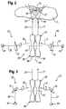
- FIG. 2 to 5 illustrated embodiments of a detection arrangement according to the invention have in common that each two panoramic lenses 37, 39, as shown in Fig. 1a and 1b are shown are provided.
- a first lens 37 is associated with a transmitting device 15 comprising a transmitter 43, for example a laser source, while a second lens 39 is associated with a receiving device 21 which comprises a receiver 41, for example in the form of a photodiode.
- the embodiments of the Fig. 2 to 5 differ in the design of radiation influencing means 31, which will be discussed in more detail below.
- the operation of the detection device according to the invention is indicated in more detail.
- one monitoring area 11 is an object 13.
- due to the imaging properties of the transmitting lens 37 is a widening of the emitted radiation 17.
- the lens 37 has, for example, an effective outlet side opening angle of about 30 °.
- the emission of the radiation 17 thus takes place in a radially widening, 360 ° around the transmitting lens 37 around covering transmission range 19.
- the transmission radiation 17 is in a transmission plane 35, which is perpendicular to a common optical axis 47 of the two lenses 37th , 39 formed imaging assembly 29 runs.
- the arrangement of the two lenses 37, 39 is selected such that, starting from a desired measuring distance, the transmitting region 19 and the receiving region 23 overlap or intersect each other. This results in a detection area 27 shown in dashed lines, in which the detection device according to the invention can detect objects 13.
- Fig. 2 schematically illustrated in a plane containing the common optical axis 47 of the two lenses 37, 39. Consequently, the detection region 27 is a rotationally symmetrical region, relative to the axis 47, of the surroundings of the detection device, which extends around the imaging arrangement 29 or its axis 47 by 360 °.
- the emitted radiation 17 is from the object 13 at so-called reflection locations 33 reflected, of which in Fig. 2 only one is shown.
- the receiving lens 39 is effective in the reverse radiation propagation direction.
- the radiation 25 reflected from the detection area 27 in a reception plane 55 is imaged by the reception lens 39 onto the receiver 41.
- the detection device is thus designed symmetrically with respect to the general basic structure with respect to a plane 45 separating the transmitting side from the receiving side, which plane is perpendicular to the axis 47.
- an optically effective element 31 is arranged in the propagation path of the radiation 17 between the transmitter 43 and the transmitting lens 37.
- this is a rotating optical wedge.
- the laser beam 17 emerging from the wedge 31 moves on a conical surface, so that the laser beam 17 exiting from the transmitting lens 37 rotates about the axis 47 and thus passes over the entire detection area 27.
- a laser scanner is realized on the transmission side, although the lens 37, which provides the deflection in the detection region 27, is arranged stationarily. It is only necessary to set the optical wedge 31 in rotation. By means of this transmission-side scanning, the desired spatial resolution is ensured by the transmission lens 37 despite the complete coverage of the detection range 27 given at any time.
- a rotating optical wedge 31 is arranged.
- the transmitting-side wedge 31 and the receiving-side wedge 41 are synchronized with each other in terms of their rotational movements, that in each case a laser beam emitted into the detection range 27 is imaged on the receiver 41 after reflection on an object 13 by means of the receiving lens 39.
- This reception-side selectivity advantageously ensures that interfering radiation impinging on the receiving lens 39 is blanked out, ie that it does not reach the receiver 41. This background suppression is not mandatory.
- a means for measuring transit time is provided.
- the time required for the laser radiation to travel the distance from the transmitting device 15 to the object 13 and as reflected radiation 25 back to the receiving device 21 is measured.
- basically all conventional methods for distance measurement can be used for the detection device according to the invention, as they are known, for example, with respect to existing laser scanners. The actual distance measurement, which is thus known to the person skilled in the art, therefore need not be discussed in greater detail.
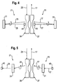
- the transmission-side scanning and the reception-side background suppression are also in the embodiments of the Fig. 3 . 4 and 5 provided, but in each case different means are used.
- the transmitter 43 and the receiver 41 are disposed outside the common optical axis 47 of the transmission lens 37 and the reception lens 39.
- the here instead of the rotating optical wedges according to Fig. 2 provided radiation influencing means in the form of the deflection means 31 not only provide for the rotation of the emitted radiation 17 and reflected radiation 25, but also correct the aforementioned deviation from the optical axis 47.
- the already mentioned micromechanical mirror 31 MEMS
- these movable mirrors 31 and electrically controllable diffractive optics can be used, as they are also basically known.
- motor-driven tumbling mirrors can also be used as influencing means 31.
- Fig. 5 also shows a central arrangement of the optoelectronic components.
- the deflection of the transmission direction or viewing direction takes place here by electrically controllable diffractive optics 31, as they have also already been mentioned.
- the transmitter 43 and the receiver 41 are respectively in the focal point of the associated lens 37 and lens 39th
Landscapes
- Physics & Mathematics (AREA)
- Engineering & Computer Science (AREA)
- Radar, Positioning & Navigation (AREA)
- Remote Sensing (AREA)
- General Physics & Mathematics (AREA)
- Computer Networks & Wireless Communication (AREA)
- Electromagnetism (AREA)
- Optics & Photonics (AREA)
- Optical Radar Systems And Details Thereof (AREA)
- Measurement Of Optical Distance (AREA)
Claims (20)
- Dispositif pour la détection en résolution locale d'objets (13) qui se trouvent dans une zone de surveillance (11),
comprenant un système émetteur (15) pour émettre un rayonnement électromagnétique (17) dans une zone d'émission (19),
comprenant un système récepteur (21) pour recevoir un rayonnement (25) réfléchi depuis une zone de réception (23),
la zone d'émission (19) et la zone de réception (23) se chevauchent ou se recoupent dans une zone de détection (27), située à l'intérieur de la zone de surveillance (11) et couvrant un angle de détection, dans laquelle le rayonnement émis (17) est réfléchi par des objets (13),
comprenant un agencement d'imagerie (29) situé dans le trajet de propagation du rayonnement émis (17) et/ou du rayonnement réfléchi (25), qui couvre à chaque instant la totalité de la zone de détection (27) du côté émission et/ou du côté réception, et
comprenant des moyens à résolution locale (31) pour distinguer le rayonnement réfléchi (25) pour ce qui concerne le lieu de réflexion (33),
caractérisé en ce que
le système récepteur (21) comprend, des moyens destinés à influencer le rayonnement (31), réalisés à titre de moyens à résolution locale (31), afin d'influencer de manière variable dans le temps la direction de propagation du rayonnement réfléchi (25), les moyens destinés à influencer le rayonnement (31) étant agencés dans le trajet de propagation du rayonnement (25) entre l'agencement d'imagerie (29) et un récepteur (41) du système récepteur (21), et/ou
en ce que le système émetteur (15) comprend des moyens destinés à influencer le rayonnement (31), réalisés à titre de moyens à résolution locale (31), afin d'influencer de manière variable dans le temps la direction de propagation du rayonnement (17), les moyens destinés à influencer le rayonnement (31) étant agencés dans le trajet de propagation du rayonnement (17) entre un émetteur (43) du système émetteur (15) et l'agencement d'imagerie (29). - Dispositif selon la revendication 1,
caractérisé en ce que le la zone de détection (27) inclut une pluralité de lieux de réflexion possibles (33). - Dispositif selon la revendication 1 ou 2,
caractérisé en ce que l'angle de détection, au moins dans un plan d'émission (35), s'élève à au moins 90°, de préférence à au moins 180°, et en particulier de manière préférée à 360°. - Dispositif selon l'une des revendications précédentes,
caractérisé en ce qu'il est réalisé à titre d'appareil de mesure d'éloignement, et en particulier en ce qu'une valeur d'éloignement peut être déterminée pour chaque lieu de réflexion (33). - Dispositif selon l'une des revendications précédentes,
caractérisé en ce qu'il est réalisé en vue de la mesure d'éloignement selon le principe de mesure du temps de parcours et/ou selon le principe de mesure de phase. - Dispositif selon l'une des revendications précédentes,
caractérisé en ce qu'il est réalisé comme un scanner à laser qui palpe la zone de réception (27) de manière pulsée dans le temps ou de manière continue. - Dispositif selon l'une des revendications précédentes,
caractérisé en ce que le système émetteur (15) est réalisé pour émettre le rayonnement (17) dans au moins un plan d'émission (35). - Dispositif selon l'une des revendications précédentes,
caractérisé en ce que l'agencement d'imagerie (29) est réalisé pour dévier le rayonnement émis (17) et/ou le rayonnement réfléchi (25). - Dispositif selon l'une des revendications précédentes,
caractérisé en ce que l'agencement d'imagerie (29) comprend au moins un élément optiquement actif, en particulier une lentille panorama et/ou une lentille omnidirectionnelle, ou une surface de réflexion de rayonnement, de préférence un miroir de forme au moins partiellement conique. - Dispositif selon l'une des revendications précédentes,
caractérisé en ce que l'agencement d'imagerie (29) comprend un système d'imagerie commun qui est actif aussi bien du côté émission que du côté réception. - Dispositif selon l'une des revendications 1 à 9,
caractérisé en ce que l'agencement d'imagerie (29) comprend aussi bien du côté émission que du côté réception respectivement un système d'imagerie séparé (37, 39), et les systèmes d'imagerie (37, 39) sont en particulier de même construction. - Dispositif selon l'une des revendications précédentes,
caractérisé en ce que les moyens à résolution locale (31) sont actifs du côté réception, et le système émetteur (15) en particulier est réalisé pour envoyer à un instant un rayonnement émis (17) sur la totalité de la zone de détection (27), en particulier au moyen de l'agencement d'imagerie (29). - Dispositif selon l'une des revendications précédentes,
caractérisé en ce que le système récepteur (21) comprend un récepteur (41) qui est subdivisé en une pluralité de récepteurs individuels, lesquels sont associés respectivement à au moins un lieu de réflexion (33). - Dispositif selon l'une des revendications précédentes,
caractérisé en ce qu'il est prévu un système qui, par référence au lieu de réflexion (33), sert à la détection sélective du rayonnement réfléchi (25) au moyen du système récepteur (21). - Dispositif selon l'une des revendications précédentes,
caractérisé en ce qu'un masque mobile est agencé dans le trajet de propagation du rayonnement réfléchi (25) entre l'agencement d'imagerie (29) et un récepteur (41) du système récepteur (21). - Dispositif selon l'une des revendications précédentes,
caractérisé en ce que les moyens à résolution locale (31) sont actifs du côté émission. - Dispositif selon l'une des revendications précédentes,
caractérisé en ce qu'il est prévu un système qui, par référence au lieu de réflexion (33), sert à l'émission sélective du rayonnement (17) au moyen du système émetteur (15). - Dispositif selon l'une des revendications précédentes,
caractérisé en ce que les moyens destinés à influencer le rayonnement (31) comprennent au moins un élément optique mobile, capable d'être piloté pour exécuter des mouvements de déflexion, en particulier un miroir, un prisme ou un coin, et/ou au moins une optique de diffraction capable d'être pilotée pour modifier le comportement de réfraction du rayonnement. - Dispositif selon l'une des revendications précédentes,
caractérisé en ce qu'il est constitué de manière symétrique, par référence à un plan (45) séparant le côté émission du côté réception, au moins pour ce qui concerne le mode de fonctionnement de principe. - Utilisation d'un agencement d'imagerie (29),
qui couvre complètement à chaque instant une zone de détection (27) du côté émission et/ou côté réception,
en particulier une lentille panorama, une lentille omnidirectionnelle ou un miroir de forme au moins partiellement conique,
dans un dispositif pour la détection en résolution locale d'objets (13) qui se trouvent dans une zone de surveillance (11), en particulier un dispositif selon l'une des revendications précédentes,
dans lequel le dispositif comprend un système émetteur (15) pour émettre un rayonnement électromagnétique (17) dans une zone d'émission (19), et un système récepteur (21) pour recevoir un rayonnement (25) réfléchi depuis une zone de réception (23), la zone d'émission (19) et la zone de réception (23) se chevauchant ou se recoupant dans la zone de détection (27), située à l'intérieur de la zone de surveillance (11) et couvrant un angle de détection, dans laquelle le rayonnement émis (17) est réfléchi par des objets (13),
dans lequel l'agencement d'imagerie (29) est situé dans le trajet de propagation du rayonnement émis (17) et/ou du rayonnement réfléchi (25), et
dans lequel le dispositif comprend des moyens à résolution locale (31) pour distinguer le rayonnement réfléchi (25) pour ce qui concerne le lieu de réflexion (33),
caractérisé en ce que
le système récepteur (21) comprend des moyens destinés à influencer le rayonnement (31), réalisés sous forme de moyens à résolution locale (31), pour influencer de manière variable dans le temps la direction de propagation du rayonnement réfléchi (25), lesdits moyens destinés à influencer le rayonnement (31) étant agencés dans le trajet de propagation du rayonnement (25) entre l'agencement imagerie (29) et un récepteur (41) du système récepteur (21), et/ou
en ce que le système émetteur (15) comprend des moyens destinés à influencer le rayonnement (31 ), réalisés sous forme de moyens à résolution locale (31), pour influencer de manière variable dans le temps la direction de propagation du rayonnement (17), lesdits moyens destinés à influencer le rayonnement (31) étant agencés dans le trajet de propagation du rayonnement (17) entre un émetteur (43) du système émetteur (15) et l'agencement d'imagerie (29).
Priority Applications (3)
| Application Number | Priority Date | Filing Date | Title |
|---|---|---|---|
| AT08005342T ATE543105T1 (de) | 2008-03-20 | 2008-03-20 | Omnidirektionales lidar system |
| EP08005342A EP2124069B1 (fr) | 2008-03-20 | 2008-03-20 | Système LIDAR omnidirectionnel |
| JP2009068684A JP2009229462A (ja) | 2008-03-20 | 2009-03-19 | 検出装置 |
Applications Claiming Priority (1)
| Application Number | Priority Date | Filing Date | Title |
|---|---|---|---|
| EP08005342A EP2124069B1 (fr) | 2008-03-20 | 2008-03-20 | Système LIDAR omnidirectionnel |
Publications (2)
| Publication Number | Publication Date |
|---|---|
| EP2124069A1 EP2124069A1 (fr) | 2009-11-25 |
| EP2124069B1 true EP2124069B1 (fr) | 2012-01-25 |
Family
ID=39483813
Family Applications (1)
| Application Number | Title | Priority Date | Filing Date |
|---|---|---|---|
| EP08005342A Active EP2124069B1 (fr) | 2008-03-20 | 2008-03-20 | Système LIDAR omnidirectionnel |
Country Status (3)
| Country | Link |
|---|---|
| EP (1) | EP2124069B1 (fr) |
| JP (1) | JP2009229462A (fr) |
| AT (1) | ATE543105T1 (fr) |
Cited By (5)
| Publication number | Priority date | Publication date | Assignee | Title |
|---|---|---|---|---|
| DE102012101811B3 (de) * | 2012-03-05 | 2012-11-22 | Sick Ag | Lichtquelle für einen Sensor und entfernungsmessender optoelektronischer Sensor |
| DE202012100760U1 (de) | 2012-03-05 | 2013-06-06 | Sick Ag | Lichtquelle für einen Sensor und entfernungsmessender optoelektronischer Sensor |
| DE102012025281A1 (de) | 2012-12-21 | 2014-06-26 | Valeo Schalter Und Sensoren Gmbh | Optische Objekterfassungseinrichtung mit einem MEMS und Kraftfahrzeug mit einer solchen Erfassungseinrichtung |
| US20200081129A1 (en) * | 2018-09-10 | 2020-03-12 | Veoneer Us, Inc. | Detection system for a vehicle |
| DE102018133302A1 (de) | 2018-12-21 | 2020-06-25 | Valeo Schalter Und Sensoren Gmbh | Optische Vorrichtung und optische Sensoreinrichtung mit einer solchen Vorrichtung und Kraftfahrzeug mit einer solchen optischen Sensoreinrichtung |
Families Citing this family (19)
| Publication number | Priority date | Publication date | Assignee | Title |
|---|---|---|---|---|
| EP2202533A1 (fr) | 2008-12-23 | 2010-06-30 | IBEO Automobile Sensor GmbH | Dispositif de détection |
| FI20105058A0 (fi) | 2010-01-22 | 2010-01-22 | Valtion Teknillinen | Omnidirektionaalinen linssi, linssiä hyödyntävät optiset laitteet sekä menetelmä optiseksi mittaamiseksi |
| DE102010039945B4 (de) * | 2010-08-30 | 2012-04-19 | Carl Zeiss Ag | Verfahren und Vorrichtungen zur Positionsbestimmung |
| RU2522742C2 (ru) * | 2012-08-07 | 2014-07-20 | Федеральное государственное бюджетное образовательное учреждение высшего профессионального образования "Новосибирский государственный технический университет" | Измеритель линейных перемещений |
| DE102016200109A1 (de) | 2015-09-18 | 2017-03-23 | Fraunhofer-Gesellschaft zur Förderung der angewandten Forschung e.V. | Vorrichtung und Verfahren zur Erfassung von Gegenständen in einem Erfassungsbereich |
| US10063849B2 (en) | 2015-09-24 | 2018-08-28 | Ouster, Inc. | Optical system for collecting distance information within a field |
| US9992477B2 (en) | 2015-09-24 | 2018-06-05 | Ouster, Inc. | Optical system for collecting distance information within a field |
| AU2017315762B2 (en) | 2016-08-24 | 2020-04-09 | Ouster, Inc. | Optical system for collecting distance information within a field |
| CN106959451A (zh) * | 2017-03-17 | 2017-07-18 | 深圳大学 | 一种激光雷达和激光雷达的探测方法 |
| DE202018006696U1 (de) | 2017-05-15 | 2022-04-01 | Ouster, Inc. | Optischer Bildübertrager mit Helligkeitsverbesserung |
| US11585901B2 (en) | 2017-11-15 | 2023-02-21 | Veoneer Us, Llc | Scanning lidar system and method with spatial filtering for reduction of ambient light |
| US11340336B2 (en) | 2017-12-07 | 2022-05-24 | Ouster, Inc. | Rotating light ranging system with optical communication uplink and downlink channels |
| US10739189B2 (en) | 2018-08-09 | 2020-08-11 | Ouster, Inc. | Multispectral ranging/imaging sensor arrays and systems |
| US10732032B2 (en) | 2018-08-09 | 2020-08-04 | Ouster, Inc. | Scanning sensor array with overlapping pass bands |
| JP2022505031A (ja) | 2018-11-13 | 2022-01-14 | ニューロ・インコーポレーテッド | 車両の死角検出のためのlidar |
| US11579257B2 (en) | 2019-07-15 | 2023-02-14 | Veoneer Us, Llc | Scanning LiDAR system and method with unitary optical element |
| US12044800B2 (en) | 2021-01-14 | 2024-07-23 | Magna Electronics, Llc | Scanning LiDAR system and method with compensation for transmit laser pulse effects |
| US11732858B2 (en) | 2021-06-18 | 2023-08-22 | Veoneer Us, Llc | Headlight illumination system using optical element |
| US12092278B2 (en) | 2022-10-07 | 2024-09-17 | Magna Electronics, Llc | Generating a spotlight |
Family Cites Families (5)
| Publication number | Priority date | Publication date | Assignee | Title |
|---|---|---|---|---|
| US3786757A (en) | 1972-06-22 | 1974-01-22 | Raytheon Co | Optical lens arrangement |
| US5018447A (en) | 1990-05-03 | 1991-05-28 | The United States Of America As Represented By The Secretary Of The Army | Device and method for monitoring the presence of an object in space |
| US6204916B1 (en) * | 1998-02-03 | 2001-03-20 | Minolta Co., Ltd. | Three dimensional information measurement method and apparatus |
| SE517696C2 (sv) * | 2000-02-08 | 2002-07-02 | Saab Ab | Anordning vid laser |
| US6839127B1 (en) * | 2003-09-15 | 2005-01-04 | Deere & Company | Optical range finder having a micro-mirror array |
-
2008
- 2008-03-20 EP EP08005342A patent/EP2124069B1/fr active Active
- 2008-03-20 AT AT08005342T patent/ATE543105T1/de active
-
2009
- 2009-03-19 JP JP2009068684A patent/JP2009229462A/ja active Pending
Cited By (7)
| Publication number | Priority date | Publication date | Assignee | Title |
|---|---|---|---|---|
| DE102012101811B3 (de) * | 2012-03-05 | 2012-11-22 | Sick Ag | Lichtquelle für einen Sensor und entfernungsmessender optoelektronischer Sensor |
| DE202012100760U1 (de) | 2012-03-05 | 2013-06-06 | Sick Ag | Lichtquelle für einen Sensor und entfernungsmessender optoelektronischer Sensor |
| US8810805B2 (en) | 2012-03-05 | 2014-08-19 | Sick Ag | Light source for a sensor and a distance-measuring optoelectronic sensor |
| DE102012025281A1 (de) | 2012-12-21 | 2014-06-26 | Valeo Schalter Und Sensoren Gmbh | Optische Objekterfassungseinrichtung mit einem MEMS und Kraftfahrzeug mit einer solchen Erfassungseinrichtung |
| WO2014095105A1 (fr) | 2012-12-21 | 2014-06-26 | Valeo Schalter Und Sensoren Gmbh | Système optique de détection d'objets à mems et véhicule à moteur équipé d'un tel système de détection |
| US20200081129A1 (en) * | 2018-09-10 | 2020-03-12 | Veoneer Us, Inc. | Detection system for a vehicle |
| DE102018133302A1 (de) | 2018-12-21 | 2020-06-25 | Valeo Schalter Und Sensoren Gmbh | Optische Vorrichtung und optische Sensoreinrichtung mit einer solchen Vorrichtung und Kraftfahrzeug mit einer solchen optischen Sensoreinrichtung |
Also Published As
| Publication number | Publication date |
|---|---|
| ATE543105T1 (de) | 2012-02-15 |
| EP2124069A1 (fr) | 2009-11-25 |
| JP2009229462A (ja) | 2009-10-08 |
Similar Documents
| Publication | Publication Date | Title |
|---|---|---|
| EP2124069B1 (fr) | Système LIDAR omnidirectionnel | |
| EP2936193B1 (fr) | Système optique de détection d'objets à mems et véhicule à moteur équipé d'un tel système de détection | |
| EP3022584B1 (fr) | Système de détection optoélectronique et procédé d'acquisition par balayage de l'environnement d'un véhicule automobile | |
| EP2202533A1 (fr) | Dispositif de détection | |
| EP2927711B1 (fr) | Lecteur laser et procédé de saisie sécurisée d'objets | |
| EP2296002B1 (fr) | Scanner optoélectronique pour la détermination de distances en azimut et élévation | |
| EP2378309B1 (fr) | Capteur optoélectronique et procédé de production d'informations sur des objets dans une zone de surveillance | |
| EP3078985B1 (fr) | Capteur optoelectronique et procede de surveillance de transmission d'un disque frontal | |
| DE10146692B4 (de) | Entfernungsbildsensor | |
| EP3032275B1 (fr) | Capteur optoelectronique et procede destine a la saisie d'objets | |
| DE102016114995A1 (de) | Vorrichtung und Verfahren zur Aufnahme von Entfernungsbildern | |
| DE10244641A1 (de) | Optoelektronische Erfassungseinrichtung | |
| EP2482094B1 (fr) | Capteur optoélectronique mesurant l'éloignement et procédé de détection d'objet | |
| DE102013012789A1 (de) | Abtastende optoelektronische Detektionseinrichtung und Kraftfahrzeug mit einer solchen Detektionseinrichtung | |
| EP2645125B1 (fr) | Laser scanner et procédé destiné à la détection d'objets dans une zone de surveillance | |
| DE102011000863A1 (de) | Optoelektronischer Sensor und Verfahren zur Erfassung von Objekten | |
| EP2637057A1 (fr) | Source lumineuse pour un capteur et capteur optoélectronique mesurant l'éloignement | |
| DE102016004334A1 (de) | Sensoreinrichtung zur Erfassung von Umgebungsinformationen und Verfahren zum Betreiben derselben | |
| EP1515157A1 (fr) | Dispositif de détection optoélectronique | |
| EP1118874A2 (fr) | Dispositif de balayage optique | |
| EP3862780B1 (fr) | Balayeur laser de sécurité et procédé de surveillance de vitre frontale | |
| WO2017001038A1 (fr) | Système de capteur pour la détection de l'environnement et procédé de reconnaissance d'une position de point zéro d'une unité rotative d'un tel système de capteur | |
| DE202011052106U1 (de) | Entfernungsmessender optoelektronischer Sensor | |
| EP3519858A1 (fr) | Unité de balayage d'un dispositif de réception et d'émission optique d'un dispositif de détection optique d'un véhicule | |
| DE102021203829A1 (de) | Reichweitenoptimiertes LiDAR-System sowie LiDAR-Vorrichtung (110) und Steuereinrichtung für ein solches LiDAR-System |
Legal Events
| Date | Code | Title | Description |
|---|---|---|---|
| PUAI | Public reference made under article 153(3) epc to a published international application that has entered the european phase |
Free format text: ORIGINAL CODE: 0009012 |
|
| 17P | Request for examination filed |
Effective date: 20081105 |
|
| AK | Designated contracting states |
Kind code of ref document: A1 Designated state(s): AT BE BG CH CY CZ DE DK EE ES FI FR GB GR HR HU IE IS IT LI LT LU LV MC MT NL NO PL PT RO SE SI SK TR |
|
| AX | Request for extension of the european patent |
Extension state: AL BA MK RS |
|
| AKX | Designation fees paid |
Designated state(s): AT BE BG CH CY CZ DE DK EE ES FI FR GB GR HR HU IE IS IT LI LT LU LV MC MT NL NO PL PT RO SE SI SK TR |
|
| RAP1 | Party data changed (applicant data changed or rights of an application transferred) |
Owner name: SICK AG |
|
| GRAP | Despatch of communication of intention to grant a patent |
Free format text: ORIGINAL CODE: EPIDOSNIGR1 |
|
| RTI1 | Title (correction) |
Free format text: OMNIDIRECTIONAL LIDAR SYSTEM |
|
| GRAS | Grant fee paid |
Free format text: ORIGINAL CODE: EPIDOSNIGR3 |
|
| GRAA | (expected) grant |
Free format text: ORIGINAL CODE: 0009210 |
|
| AK | Designated contracting states |
Kind code of ref document: B1 Designated state(s): AT BE BG CH CY CZ DE DK EE ES FI FR GB GR HR HU IE IS IT LI LT LU LV MC MT NL NO PL PT RO SE SI SK TR |
|
| REG | Reference to a national code |
Ref country code: GB Ref legal event code: FG4D Free format text: NOT ENGLISH |
|
| REG | Reference to a national code |
Ref country code: CH Ref legal event code: EP |
|
| REG | Reference to a national code |
Ref country code: AT Ref legal event code: REF Ref document number: 543105 Country of ref document: AT Kind code of ref document: T Effective date: 20120215 |
|
| REG | Reference to a national code |
Ref country code: IE Ref legal event code: FG4D |
|
| REG | Reference to a national code |
Ref country code: SE Ref legal event code: TRGR |
|
| REG | Reference to a national code |
Ref country code: DE Ref legal event code: R096 Ref document number: 502008006160 Country of ref document: DE Effective date: 20120322 |
|
| REG | Reference to a national code |
Ref country code: NL Ref legal event code: VDEP Effective date: 20120125 |
|
| LTIE | Lt: invalidation of european patent or patent extension |
Effective date: 20120125 |
|
| PG25 | Lapsed in a contracting state [announced via postgrant information from national office to epo] |
Ref country code: HR Free format text: LAPSE BECAUSE OF FAILURE TO SUBMIT A TRANSLATION OF THE DESCRIPTION OR TO PAY THE FEE WITHIN THE PRESCRIBED TIME-LIMIT Effective date: 20120125 Ref country code: NO Free format text: LAPSE BECAUSE OF FAILURE TO SUBMIT A TRANSLATION OF THE DESCRIPTION OR TO PAY THE FEE WITHIN THE PRESCRIBED TIME-LIMIT Effective date: 20120425 Ref country code: BG Free format text: LAPSE BECAUSE OF FAILURE TO SUBMIT A TRANSLATION OF THE DESCRIPTION OR TO PAY THE FEE WITHIN THE PRESCRIBED TIME-LIMIT Effective date: 20120425 Ref country code: IS Free format text: LAPSE BECAUSE OF FAILURE TO SUBMIT A TRANSLATION OF THE DESCRIPTION OR TO PAY THE FEE WITHIN THE PRESCRIBED TIME-LIMIT Effective date: 20120525 Ref country code: NL Free format text: LAPSE BECAUSE OF FAILURE TO SUBMIT A TRANSLATION OF THE DESCRIPTION OR TO PAY THE FEE WITHIN THE PRESCRIBED TIME-LIMIT Effective date: 20120125 Ref country code: LT Free format text: LAPSE BECAUSE OF FAILURE TO SUBMIT A TRANSLATION OF THE DESCRIPTION OR TO PAY THE FEE WITHIN THE PRESCRIBED TIME-LIMIT Effective date: 20120125 |
|
| REG | Reference to a national code |
Ref country code: IE Ref legal event code: FD4D |
|
| PG25 | Lapsed in a contracting state [announced via postgrant information from national office to epo] |
Ref country code: PT Free format text: LAPSE BECAUSE OF FAILURE TO SUBMIT A TRANSLATION OF THE DESCRIPTION OR TO PAY THE FEE WITHIN THE PRESCRIBED TIME-LIMIT Effective date: 20120525 Ref country code: LV Free format text: LAPSE BECAUSE OF FAILURE TO SUBMIT A TRANSLATION OF THE DESCRIPTION OR TO PAY THE FEE WITHIN THE PRESCRIBED TIME-LIMIT Effective date: 20120125 Ref country code: PL Free format text: LAPSE BECAUSE OF FAILURE TO SUBMIT A TRANSLATION OF THE DESCRIPTION OR TO PAY THE FEE WITHIN THE PRESCRIBED TIME-LIMIT Effective date: 20120125 Ref country code: GR Free format text: LAPSE BECAUSE OF FAILURE TO SUBMIT A TRANSLATION OF THE DESCRIPTION OR TO PAY THE FEE WITHIN THE PRESCRIBED TIME-LIMIT Effective date: 20120426 |
|
| PG25 | Lapsed in a contracting state [announced via postgrant information from national office to epo] |
Ref country code: CY Free format text: LAPSE BECAUSE OF FAILURE TO SUBMIT A TRANSLATION OF THE DESCRIPTION OR TO PAY THE FEE WITHIN THE PRESCRIBED TIME-LIMIT Effective date: 20120125 |
|
| BERE | Be: lapsed |
Owner name: SICK A.G. Effective date: 20120331 |
|
| PG25 | Lapsed in a contracting state [announced via postgrant information from national office to epo] |
Ref country code: CZ Free format text: LAPSE BECAUSE OF FAILURE TO SUBMIT A TRANSLATION OF THE DESCRIPTION OR TO PAY THE FEE WITHIN THE PRESCRIBED TIME-LIMIT Effective date: 20120125 Ref country code: EE Free format text: LAPSE BECAUSE OF FAILURE TO SUBMIT A TRANSLATION OF THE DESCRIPTION OR TO PAY THE FEE WITHIN THE PRESCRIBED TIME-LIMIT Effective date: 20120125 Ref country code: DK Free format text: LAPSE BECAUSE OF FAILURE TO SUBMIT A TRANSLATION OF THE DESCRIPTION OR TO PAY THE FEE WITHIN THE PRESCRIBED TIME-LIMIT Effective date: 20120125 Ref country code: IE Free format text: LAPSE BECAUSE OF FAILURE TO SUBMIT A TRANSLATION OF THE DESCRIPTION OR TO PAY THE FEE WITHIN THE PRESCRIBED TIME-LIMIT Effective date: 20120125 Ref country code: MC Free format text: LAPSE BECAUSE OF NON-PAYMENT OF DUE FEES Effective date: 20120331 Ref country code: RO Free format text: LAPSE BECAUSE OF FAILURE TO SUBMIT A TRANSLATION OF THE DESCRIPTION OR TO PAY THE FEE WITHIN THE PRESCRIBED TIME-LIMIT Effective date: 20120125 Ref country code: SI Free format text: LAPSE BECAUSE OF FAILURE TO SUBMIT A TRANSLATION OF THE DESCRIPTION OR TO PAY THE FEE WITHIN THE PRESCRIBED TIME-LIMIT Effective date: 20120125 |
|
| REG | Reference to a national code |
Ref country code: CH Ref legal event code: PL |
|
| PG25 | Lapsed in a contracting state [announced via postgrant information from national office to epo] |
Ref country code: SK Free format text: LAPSE BECAUSE OF FAILURE TO SUBMIT A TRANSLATION OF THE DESCRIPTION OR TO PAY THE FEE WITHIN THE PRESCRIBED TIME-LIMIT Effective date: 20120125 |
|
| PLBE | No opposition filed within time limit |
Free format text: ORIGINAL CODE: 0009261 |
|
| STAA | Information on the status of an ep patent application or granted ep patent |
Free format text: STATUS: NO OPPOSITION FILED WITHIN TIME LIMIT |
|
| 26N | No opposition filed |
Effective date: 20121026 |
|
| PG25 | Lapsed in a contracting state [announced via postgrant information from national office to epo] |
Ref country code: CH Free format text: LAPSE BECAUSE OF NON-PAYMENT OF DUE FEES Effective date: 20120331 Ref country code: LI Free format text: LAPSE BECAUSE OF NON-PAYMENT OF DUE FEES Effective date: 20120331 Ref country code: BE Free format text: LAPSE BECAUSE OF NON-PAYMENT OF DUE FEES Effective date: 20120331 |
|
| REG | Reference to a national code |
Ref country code: DE Ref legal event code: R097 Ref document number: 502008006160 Country of ref document: DE Effective date: 20121026 |
|
| PG25 | Lapsed in a contracting state [announced via postgrant information from national office to epo] |
Ref country code: ES Free format text: LAPSE BECAUSE OF FAILURE TO SUBMIT A TRANSLATION OF THE DESCRIPTION OR TO PAY THE FEE WITHIN THE PRESCRIBED TIME-LIMIT Effective date: 20120506 |
|
| PG25 | Lapsed in a contracting state [announced via postgrant information from national office to epo] |
Ref country code: MT Free format text: LAPSE BECAUSE OF FAILURE TO SUBMIT A TRANSLATION OF THE DESCRIPTION OR TO PAY THE FEE WITHIN THE PRESCRIBED TIME-LIMIT Effective date: 20120125 |
|
| PG25 | Lapsed in a contracting state [announced via postgrant information from national office to epo] |
Ref country code: TR Free format text: LAPSE BECAUSE OF FAILURE TO SUBMIT A TRANSLATION OF THE DESCRIPTION OR TO PAY THE FEE WITHIN THE PRESCRIBED TIME-LIMIT Effective date: 20120125 |
|
| REG | Reference to a national code |
Ref country code: AT Ref legal event code: MM01 Ref document number: 543105 Country of ref document: AT Kind code of ref document: T Effective date: 20130320 |
|
| PG25 | Lapsed in a contracting state [announced via postgrant information from national office to epo] |
Ref country code: LU Free format text: LAPSE BECAUSE OF NON-PAYMENT OF DUE FEES Effective date: 20120320 |
|
| PG25 | Lapsed in a contracting state [announced via postgrant information from national office to epo] |
Ref country code: HU Free format text: LAPSE BECAUSE OF FAILURE TO SUBMIT A TRANSLATION OF THE DESCRIPTION OR TO PAY THE FEE WITHIN THE PRESCRIBED TIME-LIMIT Effective date: 20080320 |
|
| PG25 | Lapsed in a contracting state [announced via postgrant information from national office to epo] |
Ref country code: AT Free format text: LAPSE BECAUSE OF NON-PAYMENT OF DUE FEES Effective date: 20130320 |
|
| REG | Reference to a national code |
Ref country code: FR Ref legal event code: PLFP Year of fee payment: 9 |
|
| REG | Reference to a national code |
Ref country code: FR Ref legal event code: PLFP Year of fee payment: 10 |
|
| REG | Reference to a national code |
Ref country code: FR Ref legal event code: PLFP Year of fee payment: 11 |
|
| PGFP | Annual fee paid to national office [announced via postgrant information from national office to epo] |
Ref country code: FI Payment date: 20240222 Year of fee payment: 17 Ref country code: DE Payment date: 20240321 Year of fee payment: 17 Ref country code: GB Payment date: 20240325 Year of fee payment: 17 |
|
| PGFP | Annual fee paid to national office [announced via postgrant information from national office to epo] |
Ref country code: SE Payment date: 20240319 Year of fee payment: 17 Ref country code: IT Payment date: 20240311 Year of fee payment: 17 Ref country code: FR Payment date: 20240325 Year of fee payment: 17 |