EP2124069B1 - Omnidirectional Lidar system - Google Patents
Omnidirectional Lidar system Download PDFInfo
- Publication number
- EP2124069B1 EP2124069B1 EP08005342A EP08005342A EP2124069B1 EP 2124069 B1 EP2124069 B1 EP 2124069B1 EP 08005342 A EP08005342 A EP 08005342A EP 08005342 A EP08005342 A EP 08005342A EP 2124069 B1 EP2124069 B1 EP 2124069B1
- Authority
- EP
- European Patent Office
- Prior art keywords
- radiation
- accordance
- transmission
- reception
- detection
- Prior art date
- Legal status (The legal status is an assumption and is not a legal conclusion. Google has not performed a legal analysis and makes no representation as to the accuracy of the status listed.)
- Active
Links
Images

Classifications
-
- G—PHYSICS
- G01—MEASURING; TESTING
- G01S—RADIO DIRECTION-FINDING; RADIO NAVIGATION; DETERMINING DISTANCE OR VELOCITY BY USE OF RADIO WAVES; LOCATING OR PRESENCE-DETECTING BY USE OF THE REFLECTION OR RERADIATION OF RADIO WAVES; ANALOGOUS ARRANGEMENTS USING OTHER WAVES
- G01S13/00—Systems using the reflection or reradiation of radio waves, e.g. radar systems; Analogous systems using reflection or reradiation of waves whose nature or wavelength is irrelevant or unspecified
- G01S13/02—Systems using reflection of radio waves, e.g. primary radar systems; Analogous systems
- G01S13/06—Systems determining position data of a target
- G01S13/42—Simultaneous measurement of distance and other co-ordinates
- G01S13/426—Scanning radar, e.g. 3D radar
-
- G—PHYSICS
- G01—MEASURING; TESTING
- G01S—RADIO DIRECTION-FINDING; RADIO NAVIGATION; DETERMINING DISTANCE OR VELOCITY BY USE OF RADIO WAVES; LOCATING OR PRESENCE-DETECTING BY USE OF THE REFLECTION OR RERADIATION OF RADIO WAVES; ANALOGOUS ARRANGEMENTS USING OTHER WAVES
- G01S17/00—Systems using the reflection or reradiation of electromagnetic waves other than radio waves, e.g. lidar systems
- G01S17/02—Systems using the reflection of electromagnetic waves other than radio waves
- G01S17/06—Systems determining position data of a target
- G01S17/42—Simultaneous measurement of distance and other co-ordinates
-
- G—PHYSICS
- G01—MEASURING; TESTING
- G01S—RADIO DIRECTION-FINDING; RADIO NAVIGATION; DETERMINING DISTANCE OR VELOCITY BY USE OF RADIO WAVES; LOCATING OR PRESENCE-DETECTING BY USE OF THE REFLECTION OR RERADIATION OF RADIO WAVES; ANALOGOUS ARRANGEMENTS USING OTHER WAVES
- G01S7/00—Details of systems according to groups G01S13/00, G01S15/00, G01S17/00
- G01S7/48—Details of systems according to groups G01S13/00, G01S15/00, G01S17/00 of systems according to group G01S17/00
- G01S7/481—Constructional features, e.g. arrangements of optical elements
- G01S7/4811—Constructional features, e.g. arrangements of optical elements common to transmitter and receiver
-
- G—PHYSICS
- G02—OPTICS
- G02B—OPTICAL ELEMENTS, SYSTEMS OR APPARATUS
- G02B26/00—Optical devices or arrangements for the control of light using movable or deformable optical elements
- G02B26/08—Optical devices or arrangements for the control of light using movable or deformable optical elements for controlling the direction of light
- G02B26/0875—Optical devices or arrangements for the control of light using movable or deformable optical elements for controlling the direction of light by means of one or more refracting elements
- G02B26/0883—Optical devices or arrangements for the control of light using movable or deformable optical elements for controlling the direction of light by means of one or more refracting elements the refracting element being a prism
-
- G—PHYSICS
- G02—OPTICS
- G02B—OPTICAL ELEMENTS, SYSTEMS OR APPARATUS
- G02B26/00—Optical devices or arrangements for the control of light using movable or deformable optical elements
- G02B26/08—Optical devices or arrangements for the control of light using movable or deformable optical elements for controlling the direction of light
- G02B26/10—Scanning systems
-
- G—PHYSICS
- G01—MEASURING; TESTING
- G01S—RADIO DIRECTION-FINDING; RADIO NAVIGATION; DETERMINING DISTANCE OR VELOCITY BY USE OF RADIO WAVES; LOCATING OR PRESENCE-DETECTING BY USE OF THE REFLECTION OR RERADIATION OF RADIO WAVES; ANALOGOUS ARRANGEMENTS USING OTHER WAVES
- G01S17/00—Systems using the reflection or reradiation of electromagnetic waves other than radio waves, e.g. lidar systems
- G01S17/02—Systems using the reflection of electromagnetic waves other than radio waves
- G01S17/06—Systems determining position data of a target
- G01S17/08—Systems determining position data of a target for measuring distance only
- G01S17/10—Systems determining position data of a target for measuring distance only using transmission of interrupted, pulse-modulated waves
-
- G—PHYSICS
- G01—MEASURING; TESTING
- G01S—RADIO DIRECTION-FINDING; RADIO NAVIGATION; DETERMINING DISTANCE OR VELOCITY BY USE OF RADIO WAVES; LOCATING OR PRESENCE-DETECTING BY USE OF THE REFLECTION OR RERADIATION OF RADIO WAVES; ANALOGOUS ARRANGEMENTS USING OTHER WAVES
- G01S17/00—Systems using the reflection or reradiation of electromagnetic waves other than radio waves, e.g. lidar systems
- G01S17/02—Systems using the reflection of electromagnetic waves other than radio waves
- G01S17/06—Systems determining position data of a target
- G01S17/08—Systems determining position data of a target for measuring distance only
- G01S17/32—Systems determining position data of a target for measuring distance only using transmission of continuous waves, whether amplitude-, frequency-, or phase-modulated, or unmodulated
- G01S17/36—Systems determining position data of a target for measuring distance only using transmission of continuous waves, whether amplitude-, frequency-, or phase-modulated, or unmodulated with phase comparison between the received signal and the contemporaneously transmitted signal
Definitions
- the invention relates to a device for spatially resolved detection of objects located in a surveillance area having a transmitting device for emitting electromagnetic radiation in a transmitting area and having a receiving device for receiving radiation reflected from a receiving area, wherein the transmitting area and the receiving area are within one another within the surveillance area overlap or intersect with a detection area covering and covering a detection angle, in which the emitted radiation is reflected by objects.
- An apparatus according to the preamble of claim 1 is made US 5,018,447 A known. Another device for object detection is in US 3,786,757 A described.
- Such detection devices are known in principle, for example in the form of laser scanners, which are designed as scanning laser rangefinders and the detection range with a laser beam pulsed in time or scan continuously.
- the distance measurement takes place, for example, according to a transit time measurement principle ("time of flight", TOF) or a phase measurement principle.
- TOF transit time measurement principle
- phase measurement principle a phase measurement principle.
- the TOF principle and a distance measuring method using intensity-modulated continuous wave lasers are described, for example, in the article " Intensity-modulated, stepped frequency cw lidar for distributed aerosol and hard target measurements "by Simpson et al., Published in” Applied Optics ", Vol. 44, No. 33, 20 November 2005, pp. 7210-7217 , described.
- Such detection devices are mounted, for example, on vehicles to scan the vehicle environment and thereby detect objects in sight of the device, such as other road users.
- the vehicle is effectively able to form a spatially resolved and, due to the possibility of measuring distances, also a depth-resolved image of its surroundings, this environmental detection taking place in real time.
- Versatile applications are gained with the thus obtained Environmental data possible.
- Such detection devices are also used in industrial applications.
- the one-dimensional scanning laser beam in principle, so the emitted radiation within this plane with a predetermined, the To deflect spatial resolution with determining angular resolution.
- the - also simply referred to as sensors - detection devices the - also referred to as measuring or driving beam - scanning beam by means of a motor-driven rotating prism or by means of e.g. to deflect by 45 ° to the optical axis tilted rotating mirror.
- the axis of rotation of the primate or the mirror and the optical axis of the sensor are parallel to each other.
- the entire electro-optical unit of the sensor can be made to rotate.
- both the transmit and the receive aperture are moved in a circular path, in order to ensure that the scanning beam of the sensor covers the desired angular range of up to 360 °.
- the object of the invention is to provide a detection device of the type mentioned in such a way that the above-mentioned
- the device comprises an imaging arrangement arranged in the propagation path of the emitted radiation and / or the reflected radiation, covering the entire detection area at the transmitting end and / or receiving end at all times, the device, in particular in addition to the imaging arrangement, spatial resolution means Distinguishing the reflected radiation with respect to the reflection site includes.
- the detection area is that area of the surveillance area into which the device in a sense "looks" at both the transmitter and the receiver.
- the detection area is the area in the vicinity of the device in which objects can be detected by the device, ie "seen".
- the transmitter and the receiver "look" at the detection range from different directions. In such an arrangement, in particular an overlap of Transmission area and reception area in a vicinity of the detection device can be prevented.
- the spatial resolution of the device according to the invention is also determined by the size of the cross-section which has a beam emitted into the detection area on an object on which the beam is reflected.
- the spatial resolution may be dependent on the distance between detector and object when the emitted beam has a divergence, i. expands.
- a role is also played here by the imaging properties of the optical devices used in the transmitting device, in particular the imaging arrangement according to the invention, provided that this is effective at the transmitting end.
- the imaging arrangement covers the entire detection area, the imaging arrangement "sees” a plurality of (possible) reflection locations at each point in time, where "possible” is to be understood as meaning that a reflection site can actually only be spoken of if it is in the detection area an object is located where a reflection can take place.
- the imaging device is capable of simultaneously producing a plurality of reflection locations on an object in the detection area (transmitting-side coverage) and / or "seeing" and reflecting on the receiving device (reception-side coverage) a plurality of reflection locations.
- the local resolution means are provided with the aim of a spatially resolved detection of the objects located in the surveillance area. These means are designed to distinguish the reflected radiation with respect to the reflection location.
- the invention has the advantage that the imaging assembly does not need to be moved, as it is capable of covering the entire detection range at all times.
- the spatial resolution means can be realized in many ways. In particular, the invention makes it possible to completely dispense with the movement of components for the desired spatial resolution or to reduce the masses to be moved for the desired spatial resolution to a minimum.
- detection angle can basically be chosen arbitrarily large. It is thus possible for the imaging arrangement to cover a detection angle of at least 90 °, preferably of at least 180 ° and in particular preferably of 360 °. In the latter case, there is a sensor with "all-round visibility".
- the detection device is designed as a rangefinder.
- a distance value can be determined for each (possible) reflection location.
- the device can be designed for distance measurement according to the transit time measurement principle and / or according to the phase measurement principle.
- the device is designed as a laser scanner, which pulses the detection range in time or continuously with at least one emitted laser beam.
- the transmitting device is designed to emit the radiation in at least one transmission plane.
- the detection of the environment of the device thus takes place on a circular cylinder whose height depends on the size of the cross section of the emitted radiation at the respective distance from the device.
- the imaging arrangement is designed for deflecting the emitted radiation and / or the reflected radiation. For example, a deflection by 90 °.
- an environmental detection thus takes place in a horizontal transmitting plane.
- the imaging arrangement comprises at least one optically active element.
- this element is a lens, preferably a so-called panorama lens or omnidirectional lens, or a radiation reflection surface, preferably an at least partially cone-shaped mirror.
- Such optically active elements are basically known.
- the use of such lenses is in the field of video applications.
- the invention advantageously exploits the property of such optically active elements to be able to cover a large detection area, in particular a detection angle of up to 360 °, at once, without having to move, in particular rotate, the elements therefor.
- the invention thus makes it possible for the first time to use such optically active elements in a device for spatially resolved environmental detection, in particular of panoramic lenses or omnidirectional lenses in conjunction with a laser scanner. Since, according to the invention, there is no longer any need to move, in particular rotate, components which have a comparatively large mass, the service life of the detection devices according to the invention becomes greater significantly increased compared to previously known devices. Furthermore, the invention provides for a relevant reduction of the power consumption of the detection device.
- the imaging arrangement comprises a common imaging device, which is effective both on the transmitting side and the receiving side.
- this is not mandatory.
- the imaging arrangement can comprise a separate imaging device both on the transmitter side and on the receiver side.
- These two imaging devices can in particular be of identical construction, preferably identical.
- a symmetrical basic structure of the detection device according to the invention is provided which is provided in accordance with a further embodiment and which is symmetrical with respect to a plane separating the transmission side from the reception side, with respect to at least the basic arrangement and mode of operation of the optical components.
- "symmetrical" is not to be interpreted too narrowly.
- the spatial resolution means can be effective at the receiving end.
- provision can be made, in particular, for the transmitting device to be designed to apply the emitted radiation to the entire detection area at one time.
- the receiving device may comprise a receiver which is subdivided into a plurality of individual receivers which are each assigned at least one (possible) reflection location.
- a receiver array may be provided, wherein the individual array elements are arranged in a circle, for example.
- the imaging arrangement for example, a panorama lens, consequently provides an image of the entire detection area onto the receiver array at any time.
- laser pulses which are emitted one after the other in the direction of the imaging arrangement are thus emitted in each case distributed over 360 ° into the surveillance area.
- This "all-round view" of the detection device allows it is to simultaneously measure the distance of objects around the detection device, for example according to the light transit time principle, wherein the spatial resolution is ensured by the receiver array.
- a single radiation receiver may alternatively be provided instead of the described receiver array, which is sufficiently large and arranged such that the imaging arrangement can image the entire detection area on the receiver.
- a rotating diaphragm can be provided, for example, which transmits exclusively reflected radiation incident at each time point from the respective reflection location or at the respective angle.
- the invention provides that the receiving device comprises influencing means for influencing the propagation direction of the radiation over time.
- the influencing means are arranged in the propagation path of the radiation between the imaging arrangement and a receiver of the receiving device. Specific possibilities for designing such radiation influencing means will be discussed in more detail below.
- the detection area is completely exposed to the emitted radiation at a point in time, for example by "illuminating" the entire effective area of the imaging arrangement, so as to ensure the desired spatial resolution on the receiving side
- the desired distinction between the different reflection locations can be provided, ie the spatial resolution means can be effective on the transmission side.
- a device can be provided which, with respect to the reflection sites, serves for the selective emission of the radiation by means of the transmitting device. Consequently, the imaging arrangement is no longer completely charged with the scanning radiation. Rather, it can be provided, in particular according to the principle of a conventional scanner, to apply the imaging arrangement at any time with only a single transmission beam, the direction under which this transmission beam impinging on the imaging arrangement being varied over time.
- the transmitting device additionally or alternatively comprises influencing means for influencing the propagation direction of the radiation over time.
- the influencing means are arranged in the propagation path of the radiation between a transmitter of the transmitting device and the imaging arrangement.
- the influencing means mentioned above which may be provided on the transmitting side and / or the receiving side, may in particular be movable, in particular rotatable, optical elements that can be controlled to execute deflecting movements. Such optical elements are, for example, mirrors, prisms or wedges. Both Influencing means may also be diffractive optics which are electrically controllable, for example, to change their radiation-refracting behavior.
- MEMS micromechanical mirror
- a transmitter for example a laser source, the transmitting device, a receiver, for example one or more photodiodes, the receiving device and the imaging device comprising, for example, two panoramic lenses or omnidirectional lenses, one of which is associated with the transmitting device and the other with the receiving device, can be incorporated in US Pat With respect to a base of the detection device, ie with respect to a fixedly connected to the detection device coordinate system to be immovable.
- the invention relates to the use of an imaging arrangement which at any time completely covers a detection area on the transmission side and / or reception side, in particular a panorama line, an omnidirectional lens or an at least partially cone-shaped mirror, in a device for spatially resolved detection of in a monitoring area Articles, in particular a device of the type described above, wherein the device comprises a transmitting device for emitting electromagnetic radiation in a transmission range and a receiving device for receiving radiation reflected from a receiving range, wherein the transmission range and the reception range overlap or intersect in the detection range covering a detection angle within the monitoring range and in which the emitted radiation can be reflected by objects, the imaging arrangement being in the propagation path of the emitted radiation and / or the reflected radiation Radiation is located, and wherein the device comprises spatial resolution means for distinguishing the reflected radiation with respect to the reflection site.
- the invention can be used in a variety of ways, for example in vehicle applications and in industrial applications.
- the in the Fig. 1a and 1b schematically shown Panoramalinse 37 which can be used as an imaging device in a detection device according to the invention is formed with respect to an axis 47 rotationally symmetrical.
- the incident radiation 17 Via a radiation entrance surface 51, the incident radiation 17 is reflected within the lens 37 first on a first surface 49 and then on a second surface 49.
- the radiation 17 occurs over an angular range of 360 ° ( Fig. 1b ) From the lens 37 via a circumferential exit surface 53 from.
- the radiation course is in Fig. 1a merely indicated and not physically reproduced.
- the mentioned areas are in Fig. 1b indicated by dashed or dash-dotted lines only.
- the transmitter or the emitted radiation 17 is imaged onto a 360 ° transmission range. There is a deflection of the emitted radiation 17 by 90 °.
- the radiation 17 leaving the lens 37 propagates in a transmission plane 35, which runs perpendicular to the optical axis 47 of the lens 39.
- Fig. 1a the reverse radiation course indicated.
- the Panoramalinse 37 is then effective at the receiving end, wherein from a 360 ° comprehensive reception area incident radiation 25 can be mapped to a receiver, not shown.
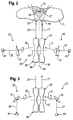
- FIG. 2 to 5 illustrated embodiments of a detection arrangement according to the invention have in common that each two panoramic lenses 37, 39, as shown in Fig. 1a and 1b are shown are provided.
- a first lens 37 is associated with a transmitting device 15 comprising a transmitter 43, for example a laser source, while a second lens 39 is associated with a receiving device 21 which comprises a receiver 41, for example in the form of a photodiode.
- the embodiments of the Fig. 2 to 5 differ in the design of radiation influencing means 31, which will be discussed in more detail below.
- the operation of the detection device according to the invention is indicated in more detail.
- one monitoring area 11 is an object 13.
- due to the imaging properties of the transmitting lens 37 is a widening of the emitted radiation 17.
- the lens 37 has, for example, an effective outlet side opening angle of about 30 °.
- the emission of the radiation 17 thus takes place in a radially widening, 360 ° around the transmitting lens 37 around covering transmission range 19.
- the transmission radiation 17 is in a transmission plane 35, which is perpendicular to a common optical axis 47 of the two lenses 37th , 39 formed imaging assembly 29 runs.
- the arrangement of the two lenses 37, 39 is selected such that, starting from a desired measuring distance, the transmitting region 19 and the receiving region 23 overlap or intersect each other. This results in a detection area 27 shown in dashed lines, in which the detection device according to the invention can detect objects 13.
- Fig. 2 schematically illustrated in a plane containing the common optical axis 47 of the two lenses 37, 39. Consequently, the detection region 27 is a rotationally symmetrical region, relative to the axis 47, of the surroundings of the detection device, which extends around the imaging arrangement 29 or its axis 47 by 360 °.
- the emitted radiation 17 is from the object 13 at so-called reflection locations 33 reflected, of which in Fig. 2 only one is shown.
- the receiving lens 39 is effective in the reverse radiation propagation direction.
- the radiation 25 reflected from the detection area 27 in a reception plane 55 is imaged by the reception lens 39 onto the receiver 41.
- the detection device is thus designed symmetrically with respect to the general basic structure with respect to a plane 45 separating the transmitting side from the receiving side, which plane is perpendicular to the axis 47.
- an optically effective element 31 is arranged in the propagation path of the radiation 17 between the transmitter 43 and the transmitting lens 37.
- this is a rotating optical wedge.
- the laser beam 17 emerging from the wedge 31 moves on a conical surface, so that the laser beam 17 exiting from the transmitting lens 37 rotates about the axis 47 and thus passes over the entire detection area 27.
- a laser scanner is realized on the transmission side, although the lens 37, which provides the deflection in the detection region 27, is arranged stationarily. It is only necessary to set the optical wedge 31 in rotation. By means of this transmission-side scanning, the desired spatial resolution is ensured by the transmission lens 37 despite the complete coverage of the detection range 27 given at any time.
- a rotating optical wedge 31 is arranged.
- the transmitting-side wedge 31 and the receiving-side wedge 41 are synchronized with each other in terms of their rotational movements, that in each case a laser beam emitted into the detection range 27 is imaged on the receiver 41 after reflection on an object 13 by means of the receiving lens 39.
- This reception-side selectivity advantageously ensures that interfering radiation impinging on the receiving lens 39 is blanked out, ie that it does not reach the receiver 41. This background suppression is not mandatory.
- a means for measuring transit time is provided.
- the time required for the laser radiation to travel the distance from the transmitting device 15 to the object 13 and as reflected radiation 25 back to the receiving device 21 is measured.
- basically all conventional methods for distance measurement can be used for the detection device according to the invention, as they are known, for example, with respect to existing laser scanners. The actual distance measurement, which is thus known to the person skilled in the art, therefore need not be discussed in greater detail.
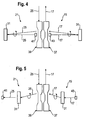
- the transmission-side scanning and the reception-side background suppression are also in the embodiments of the Fig. 3 . 4 and 5 provided, but in each case different means are used.
- the transmitter 43 and the receiver 41 are disposed outside the common optical axis 47 of the transmission lens 37 and the reception lens 39.
- the here instead of the rotating optical wedges according to Fig. 2 provided radiation influencing means in the form of the deflection means 31 not only provide for the rotation of the emitted radiation 17 and reflected radiation 25, but also correct the aforementioned deviation from the optical axis 47.
- the already mentioned micromechanical mirror 31 MEMS
- these movable mirrors 31 and electrically controllable diffractive optics can be used, as they are also basically known.
- motor-driven tumbling mirrors can also be used as influencing means 31.
- Fig. 5 also shows a central arrangement of the optoelectronic components.
- the deflection of the transmission direction or viewing direction takes place here by electrically controllable diffractive optics 31, as they have also already been mentioned.
- the transmitter 43 and the receiver 41 are respectively in the focal point of the associated lens 37 and lens 39th
Abstract
Description
Die Erfindung betrifft eine Vorrichtung zur ortsaufgelösten Erfassung von in einem Überwachungsbereich befindlichen Gegenständen mit einer Sendeeinrichtung zur Aussendung von elektromagnetischer Strahlung in einem Sendebereich und mit einer Empfangseinrichtung zum Empfang von aus einem Empfangsbereich reflektierter Strahlung, wobei sich der Sendebereich und der Empfangsbereich in einem innerhalb des Überwachungsbereichs gelegenen und einen Erfassungswinkel abdeckenden Erfassungsbereich überlappen oder schneiden, in welchem die ausgesandte Strahlung von Gegenständen reflektiert wird.The invention relates to a device for spatially resolved detection of objects located in a surveillance area having a transmitting device for emitting electromagnetic radiation in a transmitting area and having a receiving device for receiving radiation reflected from a receiving area, wherein the transmitting area and the receiving area are within one another within the surveillance area overlap or intersect with a detection area covering and covering a detection angle, in which the emitted radiation is reflected by objects.
Eine Vorrichtung gemäß dem Oberbegriff von Anspruch 1 ist aus
Derartige Erfassungsvorrichtungen sind grundsätzlich bekannt, z.B. in Form von Laserscannern, die als scannende Laserentfernungsmesser ausgebildet sind und den Erfassungsbereich mit einem Laserstrahl zeitlich gepulst oder kontinuierlich abtasten. Die Entfernungsmessung erfolgt dabei z.B. nach einem Laufzeitmessprinzip ("time of flight", TOF) oder einem Phasenmessprinzip. Das TOF-Prinzip sowie ein Entfernungsmessverfahren unter Verwendung von intensitätsmodulierten Continuous-Wave-Lasern sind beispielsweise in dem Artikel "
Derartige Erfassungsvorrichtungen werden z.B. an Fahrzeugen montiert, um die Fahrzeugumgebung abzutasten und hierdurch in Sichtweite der Vorrichtung befindliche Gegenstände, wie beispielsweise andere Verkehrsteilnehmer, zu erkennen. Hierdurch ist das Fahrzeug gewissermaßen in der Lage, sich ein ortsaufgelöstes und - aufgrund der Möglichkeit zur Messung von Entfernungen - außerdem tiefenaufgelöstes Bild von seiner Umgebung zu machen, wobei diese Umgebungserfassung in Echtzeit erfolgt. Vielfältige Anwendungen sind mit den auf diese Weise gewonnenen Umgebungsdaten möglich. Derartige Erfassungsvorrichtungen werden auch in industriellen Anwendungen eingesetzt.Such detection devices are mounted, for example, on vehicles to scan the vehicle environment and thereby detect objects in sight of the device, such as other road users. As a result, the vehicle is effectively able to form a spatially resolved and, due to the possibility of measuring distances, also a depth-resolved image of its surroundings, this environmental detection taking place in real time. Versatile applications are gained with the thus obtained Environmental data possible. Such detection devices are also used in industrial applications.
Insbesondere für scannende TOF-Laserentfernungsmesser, die einen vergleichsweise großen Winkelbereich von bis zu 360° in wenigstens einer Sende- oder Erfassungsebene überwachen sollen, ist es bekannt, den im Prinzip eindimensionalen Abtastlaserstrahl, also die ausgesandte Strahlung, innerhalb dieser Ebene mit einer vorgegebenen, die Ortsauflösung mit bestimmenden Winkelauflösung auszulenken. Hierzu ist es bekannt, in den - auch einfach als Sensoren bezeichneten - Erfassungsvorrichtungen den - auch als Mess- oder Fahrstrahl bezeichneten - Abtaststrahl mittels eines motorisch bewegten rotierenden Prismas oder mittels eines z.B. um 45° zur optischen Achse gekippten rotierenden Spiegels auszulenken. In diesen Fällen verlaufen die Rotationsachse des Primas bzw. des Spiegels und die optische Achse des Sensors parallel zueinander. In einer alternativen Ausgestaltung kann die gesamte elektrooptische Einheit des Sensors zur Rotation gebracht werden. Hierbei werden sowohl die Sendeals auch die Empfangsapertur auf einer Kreisbahn bewegt, um dafür zu sorgen, dass der Abtaststrahl des Sensors den gewünschten Winkelbereich von bis zu 360° überstreicht.In particular, for scanning TOF laser rangefinders, which are to monitor a comparatively large angular range of up to 360 ° in at least one transmission or detection plane, it is known, the one-dimensional scanning laser beam in principle, so the emitted radiation within this plane with a predetermined, the To deflect spatial resolution with determining angular resolution. For this purpose, it is known in the - also simply referred to as sensors - detection devices the - also referred to as measuring or driving beam - scanning beam by means of a motor-driven rotating prism or by means of e.g. to deflect by 45 ° to the optical axis tilted rotating mirror. In these cases, the axis of rotation of the primate or the mirror and the optical axis of the sensor are parallel to each other. In an alternative embodiment, the entire electro-optical unit of the sensor can be made to rotate. In this case, both the transmit and the receive aperture are moved in a circular path, in order to ensure that the scanning beam of the sensor covers the desired angular range of up to 360 °.
Die vorstehend genannten Lösungen haben den Nachteil, dass vergleichsweise große Massen bewegt, insbesondere in Rotation versetzt, werden müssen. Die hierzu erforderliche elektrische Leistung trägt in einem nicht unerheblichen Umfang zur gesamten Leistungsaufnahme des Sensors bei. Von Nachteil ist ferner, dass die erforderliche Lagerung der rotierenden Bauteile die Lebensdauer des Sensors signifikant begrenzt.The abovementioned solutions have the disadvantage that comparatively large masses must be moved, in particular set in rotation. The electrical power required for this purpose contributes to a not inconsiderable extent to the total power consumption of the sensor. Another disadvantage is that the required storage of the rotating components significantly limits the life of the sensor.
Aufgabe der Erfindung ist es, eine Erfassungsvorrichtung der eingangs genannten Art derart weiterzubilden, dass die vorstehend erwähntenThe object of the invention is to provide a detection device of the type mentioned in such a way that the above-mentioned
Nachteile vermieden werden, wobei insbesondere bei möglichst einfachem, störunanfälligem und eine möglichst lange Lebensdauer sicherstellendem Aufbau eine zuverlässige Erfassung von in einem Überwachungsbereich befindlichen Gegenständen über einen möglichst großen Winkelbereich von insbesondere bis zu 360° erzielbar sein soll.Disadvantages are avoided, in particular with the simplest, störunanfälligem and a long life sicherstellendem structure reliable detection of located in a surveillance area objects over the largest possible angular range of up to 360 ° should be achieved in particular.
Die Lösung dieser Aufgabe erfolgt durch die Merkmale des Anspruchs 1.The solution of this object is achieved by the features of claim 1.
Insbesondere ist erfindungsgemäß vorgesehen, dass die Vorrichtung eine im Ausbreitungsweg der ausgesandten Strahlung und/oder der reflektierten Strahlung gelegene Abbildungsanordnung umfasst, die zu jedem Zeitpunkt den gesamten Erfassungsbereich sendeseitig und/oder empfangsseitig abdeckt, wobei die Vorrichtung, insbesondere zusätzlich zu der Abbildungsanordnung, Ortsauflösungsmittel zur Unterscheidung der reflektierten Strahlung hinsichtlich des Reflexionsortes umfasst.In particular, it is provided according to the invention that the device comprises an imaging arrangement arranged in the propagation path of the emitted radiation and / or the reflected radiation, covering the entire detection area at the transmitting end and / or receiving end at all times, the device, in particular in addition to the imaging arrangement, spatial resolution means Distinguishing the reflected radiation with respect to the reflection site includes.
Bei dem Erfassungsbereich handelt es sich um denjenigen Bereich des Überwachungsbereiches, in den die Vorrichtung gewissermaßen sowohl mit der Sendeeinrichtung als auch mit der Empfangseinrichtung "blickt". Mit anderen Worten ist der Erfassungsbereich derjenige Bereich in der Umgebung der Vorrichtung, in welchem Gegenstände von der Vorrichtung detektiert, d.h. "gesehen", werden können. Prinzipiell ist es möglich, dass der Sendebereich und der Empfangsbereich mehr oder weniger zusammenfallen. Dies ist beispielsweise bei einer so genannten koaxialen Anordnung eines Senders der Sendeeinrichtung und eines Empfängers der Empfangseinrichtung bzw. der entsprechenden Optiken der Fall. Bei einer so genannten biaxialen Anordnung dagegen "blicken" der Sender und der Empfänger aus unterschiedlichen Richtungen auf den Erfassungsbereich. In einer solchen Anordnung kann insbesondere eine Überlappung von Sendebereich und Empfangsbereich in einem Nahbereich der Erfassungsvorrichtung verhindert werden.The detection area is that area of the surveillance area into which the device in a sense "looks" at both the transmitter and the receiver. In other words, the detection area is the area in the vicinity of the device in which objects can be detected by the device, ie "seen". In principle, it is possible for the transmission range and the reception range to coincide more or less. This is the case, for example, in a so-called coaxial arrangement of a transmitter of the transmitting device and a receiver of the receiving device or the corresponding optics. In a so-called biaxial arrangement, on the other hand, the transmitter and the receiver "look" at the detection range from different directions. In such an arrangement, in particular an overlap of Transmission area and reception area in a vicinity of the detection device can be prevented.
Die Ortsauflösung der erfindungsgemäßen Vorrichtung ist auch durch die Größe des Querschnitts bestimmt, die ein in den Erfassungsbereich ausgesandter Strahl auf einem Gegenstand besitzt, an welchem der Strahl reflektiert wird. Insofern kann die Ortsauflösung von der Entfernung zwischen Erfassungsvorrichtung und Gegenstand abhängig sein, wenn der ausgesandte Strahl eine Divergenz aufweist, d.h. sich aufweitet. Eine Rolle spielen hier auch die Abbildungseigenschaften der verwendeten optischen Einrichtungen der Sendeeinrichtung, insbesondere der erfindungsgemäßen Abbildungsanordnung, sofern diese sendeseitig wirksam ist.The spatial resolution of the device according to the invention is also determined by the size of the cross-section which has a beam emitted into the detection area on an object on which the beam is reflected. In this respect, the spatial resolution may be dependent on the distance between detector and object when the emitted beam has a divergence, i. expands. A role is also played here by the imaging properties of the optical devices used in the transmitting device, in particular the imaging arrangement according to the invention, provided that this is effective at the transmitting end.
Indem erfindungsgemäß die Abbildungsanordnung den gesamten Erfassungsbereich abdeckt, "sieht" die Abbildungsanordnung zu jedem Zeitpunkt eine Mehrzahl von (möglichen) Reflexionsorten, wobei "möglich" hier so zu verstehen ist, dass von einem Reflexionsort tatsächlich nur dann gesprochen werden kann, wenn sich im Erfassungsbereich ein Gegenstand befindet, an dem eine Reflexion stattfinden kann. Mit anderen Worten ist die Abbildungsanordnung dazu in der Lage, gleichzeitig eine Mehrzahl von Reflexionsorten auf einem im Erfassungsbereich befindlichen Gegenstand zu erzeugen (sendeseitige Abdeckung) und/oder eine Mehrzahl von Reflexionsorten zu "sehen" und auf der Empfangseinrichtung abzubilden (empfangsseitige Abdeckung).In accordance with the invention, the imaging arrangement covers the entire detection area, the imaging arrangement "sees" a plurality of (possible) reflection locations at each point in time, where "possible" is to be understood as meaning that a reflection site can actually only be spoken of if it is in the detection area an object is located where a reflection can take place. In other words, the imaging device is capable of simultaneously producing a plurality of reflection locations on an object in the detection area (transmitting-side coverage) and / or "seeing" and reflecting on the receiving device (reception-side coverage) a plurality of reflection locations.
Gewissermaßen als "Ausgleich" für eine derartige gleichzeitige Abdeckung des gesamten Erfassungsbereiches sind mit dem Ziel einer ortsaufgelösten Erfassung der im Überwachungsbereich befindlichen Gegenstände die Ortsauflösungsmittel vorgesehen. Diese Mittel sind zur Unterscheidung der reflektierten Strahlung hinsichtlich des Reflexionsortes ausgebildet. Die Erfindung hat den Vorteil, dass die Abbildungsanordnung nicht bewegt zu werden braucht, da sie dazu in der Lage ist, zu jedem Zeitpunkt den gesamten Erfassungsbereich abzudecken. Die Ortsauflösungsmittel können in vielfältiger Weise realisiert werden. Insbesondere ermöglicht es die Erfindung, für die gewünschte Ortsauflösung auf eine Bewegung von Bauteilen ganz zu verzichten oder die für die gewünschte Ortsauflösung zu bewegenden Massen auf ein Minimum zu reduzieren.To a certain extent as a "compensation" for such a simultaneous coverage of the entire detection area, the local resolution means are provided with the aim of a spatially resolved detection of the objects located in the surveillance area. These means are designed to distinguish the reflected radiation with respect to the reflection location. The invention has the advantage that the imaging assembly does not need to be moved, as it is capable of covering the entire detection range at all times. The spatial resolution means can be realized in many ways. In particular, the invention makes it possible to completely dispense with the movement of components for the desired spatial resolution or to reduce the masses to be moved for the desired spatial resolution to a minimum.
Der von der Abbildungsanordnung abgedeckte, d.h. "gesehene", Erfassungswinkel kann grundsätzlich beliebig groß gewählt werden. So ist es möglich, dass die Abbildungsanordnung einen Erfassungswinkel von wenigstens 90°, vorzugsweise von wenigstens 180° und insbesondere bevorzugt von 360° abdeckt. In letzterem Fall liegt ein Sensor mit "Rundumsicht" vor.The one covered by the imaging device, i. "viewed", detection angle can basically be chosen arbitrarily large. It is thus possible for the imaging arrangement to cover a detection angle of at least 90 °, preferably of at least 180 ° and in particular preferably of 360 °. In the latter case, there is a sensor with "all-round visibility".
Vorzugsweise ist die Erfassungsvorrichtung als Entfernungsmesser ausgebildet. Insbesondere ist für jeden (möglichen) Reflexionsort ein Entfernungswert bestimmbar. Die Vorrichtung kann zur Entfernungsmessung nach dem Laufzeitmessprinzip und/oder nach dem Phasenmessprinzip ausgebildet sein. Insbesondere ist die Vorrichtung als ein Laserscanner ausgebildet, der den Erfassungsbereich zeitlich gepulst oder kontinuierlich mit wenigstens einem ausgesandten Laserstrahl abtastet.Preferably, the detection device is designed as a rangefinder. In particular, a distance value can be determined for each (possible) reflection location. The device can be designed for distance measurement according to the transit time measurement principle and / or according to the phase measurement principle. In particular, the device is designed as a laser scanner, which pulses the detection range in time or continuously with at least one emitted laser beam.
Des Weiteren kann erfindungsgemäß vorgesehen sein, dass die Sendeeinrichtung zur Aussendung der Strahlung in wenigstens einer Sendeebene ausgebildet ist. Bei einem Erfassungswinkel von 360° beispielsweise erfolgt die Erfassung der Umgebung der Vorrichtung somit auf einem Kreiszylinder, dessen Höhe von der Größe des Querschnitts der ausgesandten Strahlung in der jeweiligen Entfernung von der Vorrichtung abhängt. Vorzugsweise ist die Abbildungsanordnung zur Umlenkung der ausgesandten Strahlung und/oder der reflektierten Strahlung ausgebildet. Beispielsweise erfolgt eine Umlenkung um 90°. Bei einer Anordnung der Sendeeinrichtung oberhalb oder unterhalb der Abbildungsanordnung und Aussendung der Strahlung in Richtung der Abbildungsanordnung in vertikaler Richtung erfolgt somit eine Umgebungserfassung in einer horizontalen Sendeebene.Furthermore, it can be provided according to the invention that the transmitting device is designed to emit the radiation in at least one transmission plane. At a detection angle of 360 °, for example, the detection of the environment of the device thus takes place on a circular cylinder whose height depends on the size of the cross section of the emitted radiation at the respective distance from the device. Preferably, the imaging arrangement is designed for deflecting the emitted radiation and / or the reflected radiation. For example, a deflection by 90 °. In the case of an arrangement of the transmitting device above or below the imaging arrangement and emission of the radiation in the direction of the imaging arrangement in the vertical direction, an environmental detection thus takes place in a horizontal transmitting plane.
Des Weiteren kann erfindungsgemäß vorgesehen sein, dass die Abbildungsanordnung wenigstens ein optisch wirksames Element umfasst. Bei diesem Element handelt es sich insbesondere um eine Linse, bevorzugt um eine so genannte Panoramalinse oder omnidirektionale Linse, oder um eine Strahlungsreflexionsfläche, bevorzugt um einen zumindest teilkegelförmigen Spiegel.Furthermore, it can be provided according to the invention that the imaging arrangement comprises at least one optically active element. In particular, this element is a lens, preferably a so-called panorama lens or omnidirectional lens, or a radiation reflection surface, preferably an at least partially cone-shaped mirror.
Derartige optisch wirksame Elemente, insbesondere die erwähnten Panoramalinsen bzw. omnidirektionalen Linsen, sind grundsätzlich bekannt. Der Einsatz derartiger Linsen erfolgt im Bereich von Videoanwendungen. Die Erfindung nutzt in vorteilhafter Weise die Eigenschaft derartiger optisch wirksamer Elemente dazu aus, einen großen Erfassungsbereich, der insbesondere einen Erfassungswinkel von bis zu 360° umfasst, auf einmal abdecken zu können, ohne die Elemente hierfür bewegen, insbesondere drehen, zu müssen. Die Erfindung ermöglicht somit erstmals den Einsatz derartiger optisch wirksamer Elemente in einer Vorrichtung zur ortsaufgelösten Umgebungserfassung, insbesondere von Panoramalinsen bzw. omnidirektionalen Linsen in Verbindung mit einem Laserscanner. Da erfindungsgemäß keine Notwendigkeit mehr besteht, eine vergleichsweise große Masse aufweisende Komponenten zu bewegen, insbesondere in Rotation zu versetzen, wird die Lebensdauer der erfindungsgemäßen Erfassungsvorrichtungen im Vergleich zu bislang bekannten Vorrichtungen signifikant erhöht. Des Weiteren sorgt die Erfindung für eine relevante Reduzierung der Leistungsaufnahme der Erfassungsvorrichtung.Such optically active elements, in particular the mentioned panoramic lenses or omnidirectional lenses, are basically known. The use of such lenses is in the field of video applications. The invention advantageously exploits the property of such optically active elements to be able to cover a large detection area, in particular a detection angle of up to 360 °, at once, without having to move, in particular rotate, the elements therefor. The invention thus makes it possible for the first time to use such optically active elements in a device for spatially resolved environmental detection, in particular of panoramic lenses or omnidirectional lenses in conjunction with a laser scanner. Since, according to the invention, there is no longer any need to move, in particular rotate, components which have a comparatively large mass, the service life of the detection devices according to the invention becomes greater significantly increased compared to previously known devices. Furthermore, the invention provides for a relevant reduction of the power consumption of the detection device.
In einem möglichen Ausführungsbeispiel der Erfindung umfasst die Abbildungsanordnung eine gemeinsame Abbildungseinrichtung, die sowohl sendeseitig als auch empfangsseitig wirksam ist. Dies ist jedoch nicht zwingend. Es ist auch möglich, dass die Abbildungsanordnung sowohl sendeseitig als auch empfangsseitig jeweils eine separate Abbildungseinrichtung umfasst. Diese beiden Abbildungseinrichtungen können insbesondere baugleich, bevorzugt identisch, ausgeführt sein. Hierdurch wird ein gemäß einer weiteren Ausführungsform vorgesehener, hinsichtlich zumindest der prinzipiellen Anordnung und Wirkungsweise der optischen Bauteile symmetrischer Grundaufbau der erfindungsgemäßen Erfassungsvorrichtung ermöglicht, wobei die Symmetrie bezüglich einer die Sendeseite von der Empfangsseite trennenden Ebene gegeben ist. Hierbei ist "symmetrisch" nicht zu eng auszulegen. Vielmehr sollen Unterschiede zwischen der Empfangsseite und der Sendeseite, die in Bezug auf die spezifischen Funktionen der Sendeeinrichtung einerseits und der Empfangseinrichtung andererseits erforderlich oder vorteilhaft sind (z.B. Unterschiede in der Größe der wirksamen Empfangsfläche einerseits und der wirksamen Sendefläche andererseits), an dem symmetrischen Grundaufbau an sich aber nichts ändern, von dem Begriff "Symmetrie" mit umfasst sein. So ist man naturgemäß bestrebt, in Abhängigkeit von der Größe des Empfängers die Empfangsoptik derart und insbesondere möglichst großflächig auszulegen, dass die empfangene Leistung möglichst hoch ist. Gleichzeitig kann sendeseitig dagegen eine deutlich kleinere Sendeoptik ausreichend sein.In one possible embodiment of the invention, the imaging arrangement comprises a common imaging device, which is effective both on the transmitting side and the receiving side. However, this is not mandatory. It is also possible for the imaging arrangement to comprise a separate imaging device both on the transmitter side and on the receiver side. These two imaging devices can in particular be of identical construction, preferably identical. As a result, a symmetrical basic structure of the detection device according to the invention is provided which is provided in accordance with a further embodiment and which is symmetrical with respect to a plane separating the transmission side from the reception side, with respect to at least the basic arrangement and mode of operation of the optical components. Here, "symmetrical" is not to be interpreted too narrowly. Rather, differences between the receiving side and the transmitting side, which are required or advantageous with regard to the specific functions of the transmitting device on the one hand and the receiving device on the other hand (eg differences in the size of the effective receiving surface on the one hand and the effective transmitting surface on the other hand, to the symmetrical basic structure but to change nothing, to be embraced by the term "symmetry". Thus, one naturally endeavors, depending on the size of the receiver, to design the receiving optics in such a way and in particular over as large a surface area that the received power is as high as possible. At the same time, however, a much smaller transmission optics can be sufficient on the transmission side.
In einem weiteren Ausführungsbeispiel können die Ortsauflösungsmittel empfangsseitig wirksam sein. Dabei kann insbesondere vorgesehen sein, dass die Sendeeinrichtung dazu ausgebildet ist, zu einem Zeitpunkt den gesamten Erfassungsbereich mit ausgesandter Strahlung zu beaufschlagen.In a further embodiment, the spatial resolution means can be effective at the receiving end. In this case, provision can be made, in particular, for the transmitting device to be designed to apply the emitted radiation to the entire detection area at one time.
Hierbei ist es insbesondere möglich, die gesamte wirksame Fläche der Abbildungsanordnung mittels eines Senders der Sendeeinrichtung, beispielsweise einer Laserquelle, zu "beleuchten", d.h. mit der Abtaststrahlung zu beaufschlagen. Hierdurch breitet sich die Abtaststrahlung in alle vorgesehenen Richtungen aus. Bei einem Erfassungswinkel von 360° kann die Abtaststrahlung folglich von allen Gegenständen, die sich um die Vorrichtung herum und innerhalb der Reichweite der Vorrichtung befinden, gleichzeitig reflektiert werden. Für die gewünschte Ortsauflösung wird hierbei auf der Empfangsseite gesorgt. Hierzu kann beispielsweise die Empfangseinrichtung einen Empfänger umfassen, der in eine Mehrzahl von Einzelempfängern unterteilt ist, die jeweils wenigstens einem (möglichen) Reflexionsort zugeordnet sind. Es kann beispielsweise ein Empfänger-Array vorgesehen sein, wobei die einzelnen Array-Elemente beispielsweise kreisförmig angeordnet sind. Mittels dieses Empfänger-Arrays erfolgt eine Unterscheidung der verschiedenen Reflexionsorte, an denen die ausgesandte Strahlung im Erfassungsbereich reflektiert wird oder - genauer gesagt - reflektiert werden kann, sofern sich an der betreffenden Stelle im Erfassungsbereich ein die Abtaststrahlung reflektierender Gegenstand befindet. Hierbei sorgt die Abbildungsanordnung, beispielsweise eine Panoramalinse, folglich zu jedem Zeitpunkt für eine Abbildung des gesamten Erfassungsbereiches auf das Empfänger-Array. Beispielsweise zeitlich nacheinander in Richtung der Abbildungsanordnung ausgesandte Laserpulse werden somit jeweils über 360° verteilt in den Überwachungsbereich ausgesandt. Diese "Rundumsicht" der Erfassungsvorrichtung ermöglicht es, gleichzeitig die Entfernung von um die Erfassungsvorrichtung herum befindlichen Gegenständen zu messen, beispielsweise nach dem Lichtlaufzeitprinzip, wobei die Ortsauflösung durch das Empfänger-Array sichergestellt ist.In this case, it is possible in particular to "illuminate" the entire effective area of the imaging arrangement by means of a transmitter of the transmitting device, for example a laser source, ie to act upon the scanning radiation. As a result, the scanning radiation propagates in all directions provided. Thus, at a 360 ° detection angle, the scanning radiation can be reflected simultaneously by all objects located around the device and within the range of the device. For the desired spatial resolution is provided here on the receiving side. For this purpose, for example, the receiving device may comprise a receiver which is subdivided into a plurality of individual receivers which are each assigned at least one (possible) reflection location. For example, a receiver array may be provided, wherein the individual array elements are arranged in a circle, for example. By means of this receiver array, a distinction is made between the different reflection locations at which the emitted radiation is reflected in the detection area or, more precisely, can be reflected, provided that an object reflecting the scanning radiation is located at the relevant location in the detection area. In this case, the imaging arrangement, for example, a panorama lens, consequently provides an image of the entire detection area onto the receiver array at any time. For example, laser pulses which are emitted one after the other in the direction of the imaging arrangement are thus emitted in each case distributed over 360 ° into the surveillance area. This "all-round view" of the detection device allows it is to simultaneously measure the distance of objects around the detection device, for example according to the light transit time principle, wherein the spatial resolution is ensured by the receiver array.
Bei einer solchen empfangsseitig wirksamen Ortsauflösung kann alternativ anstelle des beschriebenen Empfänger-Arrays ein einziger Strahlungsempfänger vorgesehen sein, der ausreichend groß ausgebildet und derart angeordnet ist, dass die Abbildungsanordnung den gesamten Erfassungsbereich auf dem Empfänger abbilden kann. Zur Unterscheidung der verschiedenen Reflexionsorte bzw. Erfassungsrichtungen, aus denen die im Erfassungsbereich reflektierte Strahlung einfällt, kann beispielsweise eine rotierende Blende vorgesehen sein, die zu jedem Zeitpunkt ausschließlich von dem jeweiligen Reflexionsort stammende bzw. unter dem jeweiligen Winkel einfallende reflektierte Strahlung durchlässt.In the case of such a spatial resolution effective at the receiving end, a single radiation receiver may alternatively be provided instead of the described receiver array, which is sufficiently large and arranged such that the imaging arrangement can image the entire detection area on the receiver. In order to distinguish between the different reflection locations or detection directions from which the radiation reflected in the detection area is incident, a rotating diaphragm can be provided, for example, which transmits exclusively reflected radiation incident at each time point from the respective reflection location or at the respective angle.
Eine weitere Möglichkeit zur Unterscheidung zwischen den einzelnen Reflexionsorten, also gewissermaßen zur "Ausblendung" aller zu einem bestimmten Zeitpunkt jeweils gerade nicht zu erfassenden Reflexionsorte und auch zur Ausblendung von Stör- bzw. Hintergrundstrahlung, besteht darin, empfangsseitig die Ausbreitungsrichtung der Strahlung zu beeinflussen. Hierzu ist erfindungsgemäß vorgesehen, dass die Empfangseinrichtung Beeinflussungsmittel zur zeitlich variierenden Beeinflussung der Ausbreitungsrichtung der Strahlung umfasst. Erfindungsgemäß sind die Beeinflussungsmittel im Ausbreitungsweg der Strahlung zwischen der Abbildungsanordnung und einem Empfänger der Empfangseinrichtung angeordnet. Auf konkrete Möglichkeiten zur Ausgestaltung derartiger Strahlungsbeeinflussungsmittel wird nachstehend näher eingegangen. Während vorstehend erwähnt wurde, dass in einer Variante der Erfindung der Erfassungsbereich zu einem Zeitpunkt vollständig mit der ausgesandten Strahlung beaufschlagt wird, indem beispielsweise die gesamte wirksame Fläche der Abbildungsanordnung "beleuchtet" wird, so dass für die gewünschte Ortsauflösung auf der Empfangsseite zu sorgen ist, kann in einer weiteren Variante der Erfindung zusätzlich oder alternativ auf der Sendeseite für die gewünschte Unterscheidung zwischen den verschiedenen Reflexionsorten gesorgt werden, d.h. die Ortsauflösungsmittel können sendeseitig wirksam sein.A further possibility for distinguishing between the individual reflection locations, that is to say for "blanking out" all reflection locations which can not be detected at any given time and also for suppressing interference or background radiation, is to influence the propagation direction of the radiation on the reception side. For this purpose, the invention provides that the receiving device comprises influencing means for influencing the propagation direction of the radiation over time. According to the invention, the influencing means are arranged in the propagation path of the radiation between the imaging arrangement and a receiver of the receiving device. Specific possibilities for designing such radiation influencing means will be discussed in more detail below. While it has been mentioned above, in one variant of the invention, the detection area is completely exposed to the emitted radiation at a point in time, for example by "illuminating" the entire effective area of the imaging arrangement, so as to ensure the desired spatial resolution on the receiving side, In a further variant of the invention, additionally or alternatively on the transmission side, the desired distinction between the different reflection locations can be provided, ie the spatial resolution means can be effective on the transmission side.
Es kann eine Einrichtung vorgesehen sein, die in Bezug auf die Reflexionsorte zur selektiven Aussendung der Strahlung mittels der Sendeeinrichtung dient. Die Abbildungsanordnung wird hierbei folglich nicht mehr vollständig mit der Abtaststrahlung beaufschlagt. Vielmehr kann vorgesehen sein, insbesondere nach dem Prinzip eines herkömmlichen Scanners, die Abbildungsanordnung zu jedem Zeitpunkt mit lediglich einem einzigen Sendestrahl zu beaufschlagen, wobei die Richtung, unter welcher dieser Sendestrahl auf die Abbildungsanordnung trifft, zeitlich variiert wird.A device can be provided which, with respect to the reflection sites, serves for the selective emission of the radiation by means of the transmitting device. Consequently, the imaging arrangement is no longer completely charged with the scanning radiation. Rather, it can be provided, in particular according to the principle of a conventional scanner, to apply the imaging arrangement at any time with only a single transmission beam, the direction under which this transmission beam impinging on the imaging arrangement being varied over time.
Die Sendeeinrichtung umfasst erfindungsgemäß zusätzlich oder alternativ Beeinflussungsmittel zur zeitlich variierenden Beeinflussung der Ausbreitungsrichtung der Strahlung. Erfindungsgemäß sind die Beeinflussungsmittel im Ausbreitungsweg der Strahlung zwischen einem Sender der Sendeeinrichtung und der Abbildungsanordnung angeordnet.According to the invention, the transmitting device additionally or alternatively comprises influencing means for influencing the propagation direction of the radiation over time. According to the invention, the influencing means are arranged in the propagation path of the radiation between a transmitter of the transmitting device and the imaging arrangement.
Bei den vorstehend erwähnten Beeinflussungsmitteln, die sendeseitig und/oder empfangsseitig vorgesehen sein können, kann es sich insbesondere um zur Ausführung von Ablenkbewegungen ansteuerbare bewegliche, insbesondere rotierbare, optische Elemente handeln. Derartige optische Elemente sind beispielsweise Spiegel, Prismen oder Keile. Bei den Beeinflussungsmitteln kann es sich auch um diffraktive Optiken handeln, die beispielsweise zur Veränderung ihres strahlungsbrechenden Verhaltens elektrisch ansteuerbar sind.The influencing means mentioned above, which may be provided on the transmitting side and / or the receiving side, may in particular be movable, in particular rotatable, optical elements that can be controlled to execute deflecting movements. Such optical elements are, for example, mirrors, prisms or wedges. Both Influencing means may also be diffractive optics which are electrically controllable, for example, to change their radiation-refracting behavior.
Derartige Beeinflussungsmittel sind grundsätzlich bekannt. In einem besonders bevorzugten Ausführungsbeispiel wird sendeseitig und/oder empfangsseitig jeweils wenigstens ein so genannter mikromechanischer Spiegel (MEMS) eingesetzt.Such influencing means are known in principle. In a particularly preferred embodiment, at least one so-called micromechanical mirror (MEMS) is used at the transmitting end and / or at the receiving end.
Die Erfindung ermöglicht es folglich, die für die Umgebungserfassung zu bewegenden Massen zu minimieren. Ein Sender, beispielsweise eine Laserquelle, der Sendeeinrichtung, ein Empfänger, beispielsweise ein oder mehrere Fotodioden, der Empfangseinrichtung sowie die Abbildungsanordnung, die beispielsweise zwei Panoramalinsen oder omnidirektionale Linsen umfasst, von denen die eine der Sendeeinrichtung und die andere der Empfangseinrichtung zugeordnet ist, können in Bezug auf eine Basis der Erfassungsvorrichtung, d.h. bezüglich eines fest mit der Erfassungsvorrichtung verbundenen Koordinatensystems, unbeweglich angeordnet sein.The invention thus makes it possible to minimize the masses to be moved for the environmental detection. A transmitter, for example a laser source, the transmitting device, a receiver, for example one or more photodiodes, the receiving device and the imaging device comprising, for example, two panoramic lenses or omnidirectional lenses, one of which is associated with the transmitting device and the other with the receiving device, can be incorporated in US Pat With respect to a base of the detection device, ie with respect to a fixedly connected to the detection device coordinate system to be immovable.
Gemäß einem weiteren Aspekt betrifft die Erfindung die Verwendung einer Abbildungsanordnung, die zu jedem Zeitpunkt einen Erfassungsbereich sendeseitig und/oder empfangsseitig vollständig abdeckt, insbesondere einer Panoramalinse, einer omnidirektionalen Linse oder eines zumindest teilkegelförmigen Spiegels, in einer Vorrichtung zur ortsaufgelösten Erfassung von in einem Überwachungsbereich befindlichen Gegenständen, insbesondere eine Vorrichtung der vorstehend erläuterten Art, wobei die Vorrichtung eine Sendeeinrichtung zur Aussendung von elektromagnetischer Strahlung in einem Sendebereich und eine Empfangseinrichtung zum Empfang von aus einem Empfangsbereich reflektierter Strahlung umfasst, wobei sich der Sendebereich und der Empfangsbereich in dem innerhalb des Überwachungsbereichs liegenden und einen Erfassungswinkel abdeckenden Erfassungsbereich überlappen oder schneiden, in welchem die ausgesandte Strahlung von Gegenständen reflektiert wird bzw. reflektiert werden kann, wobei die Abbildungsanordnung im Ausbreitungsweg der ausgesandten Strahlung und/oder der reflektierten Strahlung gelegen ist, und wobei die Vorrichtung Ortsauflösungsmittel zur Unterscheidung der reflektierten Strahlung hinsichtlich des Reflexionsortes umfasst.According to a further aspect, the invention relates to the use of an imaging arrangement which at any time completely covers a detection area on the transmission side and / or reception side, in particular a panorama line, an omnidirectional lens or an at least partially cone-shaped mirror, in a device for spatially resolved detection of in a monitoring area Articles, in particular a device of the type described above, wherein the device comprises a transmitting device for emitting electromagnetic radiation in a transmission range and a receiving device for receiving radiation reflected from a receiving range, wherein the transmission range and the reception range overlap or intersect in the detection range covering a detection angle within the monitoring range and in which the emitted radiation can be reflected by objects, the imaging arrangement being in the propagation path of the emitted radiation and / or the reflected radiation Radiation is located, and wherein the device comprises spatial resolution means for distinguishing the reflected radiation with respect to the reflection site.
Generell ist die Erfindung in vielfältiger Weise einsetzbar, beispielsweise in Fahrzeuganwendungen und in industriellen Anwendungen.In general, the invention can be used in a variety of ways, for example in vehicle applications and in industrial applications.
Mögliche Ausführungsformen der Erfindung sind vorstehend bereits erläutert worden und auch in den abhängigen Ansprüchen, der Beschreibung sowie der Zeichnung angegeben.Possible embodiments of the invention have already been explained above and also indicated in the dependent claims, the description and the drawing.
Die Erfindung wird im Folgenden beispielhaft unter Bezugnahme auf die Zeichnung beschrieben. Es zeigen:
- Fig. 1a und 1b
- schematisch verschiedene Ansichten eines Ausfüh- rungsbeispiels einer Abbildungseinrichtung für eine er- findungsgemäße Erfassungsvorrichtung, und
- Fig. 2 bis 5
- schematisch unterschiedliche Ausführungsformen einer erfindungsgemäßen Erfassungsvorrichtung.
- Fig. 1a and 1b
- 2 schematically shows different views of an embodiment of an imaging device for a detection device according to the invention, and FIG
- Fig. 2 to 5
- schematically different embodiments of a detection device according to the invention.
Die in den
Folglich wird mit der Panoramalinse 37 der Sender bzw. die ausgesandte Strahlung 17 auf einen 360° umfassenden Sendebereich abgebildet. Es erfolgt eine Umlenkung der ausgesandten Strahlung 17 um 90°. Die die Linse 37 verlassende Strahlung 17 breitet sich in einer Sendeebene 35 aus, die senkrecht zur optischen Achse 47 der Linse 39 verläuft.Consequently, with the
Gestrichelt ist in
Die in den
Die Ausführungsformen der
Im Ausführungsbeispiel der
Diese Situation ist in
Die Empfangslinse 39 ist in umgekehrter Strahlungsausbreitungsrichtung wirksam. Die aus den Erfassungsbereich 27 in einer Empfangsebene 55 reflektierte Strahlung 25 wird von der Empfangslinse 39 auf den Empfänger 41 abgebildet. In optischer Hinsicht ist die Erfassungsvorrichtung somit hinsichtlich des generellen Grundaufbaus symmetrisch bezüglich einer die Sendeseite von der Empfangsseite trennenden Ebene 45 ausgelegt, die senkrecht zur Achse 47 verläuft.The receiving
Um mittels der Sendelinse 37 die Strahlung 17 in unterschiedliche Richtungen auszusenden, ist im Ausbreitungsweg der Strahlung 17 zwischen dem Sender 43 und der Sendelinse 37 ein optisch wirksames Element 31 angeordnet. Im Ausführungsbeispiel der
Sendeseitig ist somit ein Laserscanner realisiert, wobei allerdings die für die Ablenkung in den Erfassungsbereich 27 sorgende Linse 37 stationär angeordnet ist. Es ist lediglich erforderlich, den optischen Keil 31 in Rotation zu versetzen. Durch dieses sendeseitige Scannen ist die gewünschte Ortsauflösung trotz der zu jedem Zeitpunkt gegebenen vollständigen Abdeckung des Erfassungsbereiches 27 durch die Sendelinse 37 gewährleistet.Thus, a laser scanner is realized on the transmission side, although the
Aufgrund der vorstehend erwähnten prinzipiellen symmetrischen Ausgestaltung der Erfassungsvorrichtung ist auch empfangsseitig im Ausbreitungsweg der reflektierten Strahlung 25 zwischen der Empfangslinse 39 und dem Empfänger 41 ein rotierender optischer Keil 31 angeordnet. Der sendeseitige Keil 31 und der empfangsseitige Keil 41 sind derart hinsichtlich ihrer Rotationsbewegungen miteinander synchronisiert, dass jeweils ein in den Erfassungsbereich 27 ausgesandter Laserstrahl nach Reflexion an einem Gegenstand 13 mittels der Empfangslinse 39 auf dem Empfänger 41 abgebildet wird. Diese empfangsseitige Selektivität stellt in vorteilhafter Weise sicher, dass auf die Empfangslinse 39 treffende Störstrahlung ausgeblendet wird, d.h. nicht auf den Empfänger 41 gelangt. Diese Hintergrundausblendung ist nicht zwingend. Alternativ ist es möglich, auf die empfangsseitig vorgesehene zeitlich variierende Beeinflussung der Ausbreitungsrichtung der reflektierten Strahlung 25 mittels des rotierenden Keils 31 zu verzichten. Es kann stattdessen z.B. ein großflächigerer Empfänger vorgesehen sein, auf den zu jedem Zeitpunkt der gesamte Erfassungsbereich 27 mittels der Empfangslinse 39 abgebildet wird. Aufgrund der erwähnten Störstrahlung oder Hintergrundstrahlung könnte sich allerdings ein gegenüber der in
Zur Bestimmung der Entfernung des Gegenstands 13 von der Erfassungsvorrichtung ist beispielsweise eine Einrichtung zur Laufzeitmessung vorgesehen. Hierbei wird die Zeit gemessen, welche die Laserstrahlung benötigt, um den Weg von der Sendeeinrichtung 15 zum Gegenstand 13 und als reflektierte Strahlung 25 zurück zur Empfangseinrichtung 21 zurückzulegen. Insofern können für die erfindungsgemäße Erfassungsvorrichtung grundsätzlich alle herkömmlichen Methoden zur Entfernungsmessung eingesetzt werden, wie sie z.B. in Bezug auf existierende Laserscanner bekannt sind. Auf die eigentliche Entfernungsmessung, die dem Fachmann somit bekannt ist, braucht daher nicht näher eingegangen zu werden.To determine the distance of the
Das sendeseitige Scannen und die empfangsseitige Hintergrundausblendung sind auch in den Ausführungsbeispielen der
In dem Ausführungsbeispiel der
Bei der zentralen Anordnung der optischen Komponenten gemäß
Das Ausführungsbeispiel der
- 1111
- Überwachungsbereichmonitoring area
- 1313
- Gegenstandobject
- 1515
- Sendeeinrichtungtransmitting device
- 1717
- ausgesandte Strahlungemitted radiation
- 1919
- Sendebereichtransmission range
- 2121
- Empfangseinrichtungreceiver
- 2323
- Empfangsbereichreception area
- 2525
- reflektierte Strahlungreflected radiation
- 2727
- Erfassungsbereichdetection range
- 2929
- AbbildungsanordnungThe imaging assembly
- 3131
- OrtsauflösungsmittelSpatial resolution means
- 3333
- Reflexionsortof reflection
- 3535
- Sendeebenetransmission level
- 3737
- Abbildungseinrichtungimaging device
- 3939
- Abbildungseinrichtungimaging device
- 4141
- Empfängerreceiver
- 4343
- Sendertransmitter
- 4545
- Symmetrieebeneplane of symmetry
- 4747
- Achse der AbbildungsanordnungAxis of the imaging arrangement
- 4949
- Reflexionsflächereflecting surface
- 5151
- Eintrittsflächeentry surface
- 5353
- Austrittsflächeexit area
- 5555
- Empfangsebenereception plane
Claims (20)
- An apparatus for the spatially resolved detection of objects (13) located in a monitored zone (11),
having a transmission device (15) for the transmission of electromagnetic radiation (17) into a transmission region (19); having a reception device (21) for the reception of radiation (25) reflected from a reception region (23),
wherein the transmission region (19) and the reception region (23) overlap or intersect in a detection region (27) which is disposed within the monitored zone (11), which covers a detection angle and in which the transmitted radiation (17) is reflected from objects (13), having an imaging arrangement (29) which is disposed in the propagation path of the transmitted radiation (17) and/ or of the reflected radiation (25) and which covers the total detection region (27) at the transmission side and/or at the reception side at all times; and
having spatial resolution means (31) for distinguishing the reflected radiation (25) with respect to the reflection location (33), characterised in that
the reception device (21) includes radiation influencing means (31) formed as spatial resolution means (31) for the time-varying influencing of the direction of propagation of the reflected radiation (25), with the radiation influencing means (31) being arranged between the imaging arrangement (29) and a receiver (41) of the reception device (21) in the propagation path of the radiation (25); and/or
in that the transmission device (15) includes radiation influencing means (31) formed as spatial resolution means (31) for the time-varying influencing of the direction of propagation of the radiation (17), with the radiation influencing means (31) being arranged between a transmitter (43) of the transmission device (15) and the imaging arrangement (29) in the propagation path of the radiation (17). - An apparatus in accordance with claim 1,
characterised in that
the detection region (27) includes a plurality of possible reflection locations (33). - An apparatus in accordance with claim 1 or 2,
characterised in that
the detection angle amounts to at least 90°, preferably to at least 180°, and in particular preferably 360°, in at least one transmission plane (35). - An apparatus in accordance with any one of the preceding claims,
characterised in that
it is designed as a distance measurement device, with a distance value in particular being able to be determined for each reflection location (33). - An apparatus in accordance with any one of the preceding claims,
characterised in that
it is designed for distance measurement in accordance with the transit time measurement principle and/or in accordance with the phase measurement principle. - An apparatus in accordance with any one of the preceding claims,
characterised in that
it is designed as a laser scanner which scans the reception region (27) in a time-pulsed or continuous manner. - An apparatus in accordance with any one of the preceding claims,
characterised in that
the transmission device (15) is designed for transmitting the radiation (17) in at least one transmission plane (35). - An apparatus in accordance with any one of the preceding claims,
characterised in that
the imaging arrangement (29) is designed for deflecting the transmitted radiation (17) and/or the reflected radiation (25). - An apparatus in accordance with any one of the preceding claims,
characterised in that
the imaging arrangement (29) includes at least one optically effective element, in particular a panoramic lens and/or an omnidirectional lens, or a radiation reflection surface, preferably an at least partly conical mirror. - An apparatus in accordance with any one of the preceding claims,
characterised in that
the imaging arrangement (29) includes a common imaging device which is effective both at the transmission side and at the reception side. - An apparatus in accordance with any one of the claims 1 to 9,
characterised in that
the imaging arrangement (29) includes a separate imaging device (37, 39) both at the transmission side and at the reception side, with in particular the imaging devices (37, 39) being of the same construction. - An apparatus in accordance with any one of the preceding claims,
characterised in that
the spatial resolution means (31) are effective at the reception side, with in particular the transmission device (15) being designed to apply transmitted radiation (17) to the total detection region (27) at one point in time, in particular by means of the imaging arrangement (29). - An apparatus in accordance with any one of the preceding claims,
characterised in that
the reception device (31) includes a receiver (41) which is divided into a plurality of individual receivers which are each associated with at least one reflection location (33). - An apparatus in accordance with any one of the preceding claims,
characterised in that
a device is provided which serves for the selection detection of the reflected radiation (25) by means of the reception device (21) with respect to the reflection locations (33). - An apparatus in accordance with any one of the preceding claims,
characterised in that
a movable diaphragm is arranged between the imaging arrangement (29) and a receiver (41) of the reception device (21) in the propagation path of the reflected radiation (25). - An apparatus in accordance with any one of the preceding claims,
characterised in that
the spatial resolution means (31) are effective at the transmission side. - An apparatus in accordance with any one of the preceding claims,
characterised in that
a device (31) is provided which serves for the selective transmission of the radiation (17) by means of the transmission device (15) with respect to the reflection locations (33). - An apparatus in accordance with any one of the preceding claims,
characterised in that
the radiation influencing means (31) include at least one movable optical element controllable for carrying out deflection movements, in particular a mirror, a prism or a wedge, and/or at least one diffractive optics controllable for changing the radiation-refraction behaviour. - An apparatus in accordance with any one of the preceding claims,
characterised in that
it is designed symmetrically with respect to a plane (45) separating the transmission side from the reception side at least with respect to the basic operation. - Use of an imaging arrangement (29),
which completely covers a detection region (27) at the transmission side and/or at the reception side at all times,
in particular of a panoramic lens, of an omnidirectional lens or of at least one partly conical mirror,
in an apparatus for the spatially resolved detection of objects (13) located in a monitored zone (11), in particular in an apparatus in accordance with any one of the preceding claims,
wherein the apparatus includes a transmission device (15) for the transmission of electromagnetic radiation (17) in a transmission region (19) and a reception device (21) for the reception of radiation (25) reflected from a reception region (23), wherein the transmission region (19) and the reception region (23) overlap or intersect in the detection region (27) which is disposed within the monitored zone (11), which covers a detection angle and in which the transmitted radiation (17) is reflected by objects (13);
wherein the imaging arrangement (29) is disposed in the propagation path of the transmitted radiation (17) and/or of the reflected radiation (25); and
wherein the apparatus includes spatial resolution means (31) for distinguishing the reflected radiation (25) with respect to the reflection location (33),
characterised in that
the reception device (21) includes radiation influencing means (31) formed as spatial resolution means (31) for the time-varying influencing of the direction of propagation of the reflected radiation (25), with the radiation influencing means (31) being arranged between the imaging arrangement (29) and a receiver (41) of the reception device (21) in the propagation path of the radiation (25); and/or
in that the transmission device (15) includes radiation influencing means (31) formed as spatial resolution means (31) for the time-varying influencing of the direction of propagation of the radiation (17), with the radiation influencing means (31) being arranged between a transmitter (43) of the transmission device (15) and the imaging arrangement (29) in the propagation path of the radiation (17).
Priority Applications (3)
| Application Number | Priority Date | Filing Date | Title |
|---|---|---|---|
| AT08005342T ATE543105T1 (en) | 2008-03-20 | 2008-03-20 | OMNIDIRECTIONAL LIDAR SYSTEM |
| EP08005342A EP2124069B1 (en) | 2008-03-20 | 2008-03-20 | Omnidirectional Lidar system |
| JP2009068684A JP2009229462A (en) | 2008-03-20 | 2009-03-19 | Detection device |
Applications Claiming Priority (1)
| Application Number | Priority Date | Filing Date | Title |
|---|---|---|---|
| EP08005342A EP2124069B1 (en) | 2008-03-20 | 2008-03-20 | Omnidirectional Lidar system |
Publications (2)
| Publication Number | Publication Date |
|---|---|
| EP2124069A1 EP2124069A1 (en) | 2009-11-25 |
| EP2124069B1 true EP2124069B1 (en) | 2012-01-25 |
Family
ID=39483813
Family Applications (1)
| Application Number | Title | Priority Date | Filing Date |
|---|---|---|---|
| EP08005342A Active EP2124069B1 (en) | 2008-03-20 | 2008-03-20 | Omnidirectional Lidar system |
Country Status (3)
| Country | Link |
|---|---|
| EP (1) | EP2124069B1 (en) |
| JP (1) | JP2009229462A (en) |
| AT (1) | ATE543105T1 (en) |
Cited By (5)
| Publication number | Priority date | Publication date | Assignee | Title |
|---|---|---|---|---|
| DE102012101811B3 (en) * | 2012-03-05 | 2012-11-22 | Sick Ag | Light source for distance-measuring optoelectronic sensor, has light guide channel filled with fluid whose refractive index is less than that of light guide, so that transmitted light is totally reflected in adjacent portions of fluid |
| DE202012100760U1 (en) | 2012-03-05 | 2013-06-06 | Sick Ag | Light source for a sensor and distance-measuring optoelectronic sensor |
| WO2014095105A1 (en) | 2012-12-21 | 2014-06-26 | Valeo Schalter Und Sensoren Gmbh | Optical object-detection device having a mems and motor vehicle having such a detection device |
| US20200081129A1 (en) * | 2018-09-10 | 2020-03-12 | Veoneer Us, Inc. | Detection system for a vehicle |
| DE102018133302A1 (en) | 2018-12-21 | 2020-06-25 | Valeo Schalter Und Sensoren Gmbh | Optical device and optical sensor device with such a device and motor vehicle with such an optical sensor device |
Families Citing this family (17)
| Publication number | Priority date | Publication date | Assignee | Title |
|---|---|---|---|---|
| EP2202533A1 (en) | 2008-12-23 | 2010-06-30 | IBEO Automobile Sensor GmbH | Logging device |
| FI20105058A0 (en) * | 2010-01-22 | 2010-01-22 | Valtion Teknillinen | Omnidirectional lens, lens utilizing optical devices and optical measurement method |
| DE102010039945B4 (en) * | 2010-08-30 | 2012-04-19 | Carl Zeiss Ag | Methods and devices for position determination |
| RU2522742C2 (en) * | 2012-08-07 | 2014-07-20 | Федеральное государственное бюджетное образовательное учреждение высшего профессионального образования "Новосибирский государственный технический университет" | Linear displacement transducer |
| DE102016200109A1 (en) | 2015-09-18 | 2017-03-23 | Fraunhofer-Gesellschaft zur Förderung der angewandten Forschung e.V. | Apparatus and method for detecting objects in a detection area |
| US9992477B2 (en) | 2015-09-24 | 2018-06-05 | Ouster, Inc. | Optical system for collecting distance information within a field |
| US10063849B2 (en) | 2015-09-24 | 2018-08-28 | Ouster, Inc. | Optical system for collecting distance information within a field |
| CA3035094A1 (en) | 2016-08-24 | 2018-03-01 | Ouster, Inc. | Optical system for collecting distance information within a field |
| CN106959451A (en) * | 2017-03-17 | 2017-07-18 | 深圳大学 | A kind of detection method of laser radar and laser radar |
| US11086013B2 (en) | 2017-05-15 | 2021-08-10 | Ouster, Inc. | Micro-optics for imaging module with multiple converging lenses per channel |
| US11585901B2 (en) | 2017-11-15 | 2023-02-21 | Veoneer Us, Llc | Scanning lidar system and method with spatial filtering for reduction of ambient light |
| US10969490B2 (en) | 2017-12-07 | 2021-04-06 | Ouster, Inc. | Light ranging system with opposing circuit boards |
| US10739189B2 (en) | 2018-08-09 | 2020-08-11 | Ouster, Inc. | Multispectral ranging/imaging sensor arrays and systems |
| US11473969B2 (en) | 2018-08-09 | 2022-10-18 | Ouster, Inc. | Channel-specific micro-optics for optical arrays |
| JP2022505031A (en) | 2018-11-13 | 2022-01-14 | ニューロ・インコーポレーテッド | LIDAR for detecting blind spots in vehicles |
| US11579257B2 (en) | 2019-07-15 | 2023-02-14 | Veoneer Us, Llc | Scanning LiDAR system and method with unitary optical element |
| US11732858B2 (en) | 2021-06-18 | 2023-08-22 | Veoneer Us, Llc | Headlight illumination system using optical element |
Family Cites Families (5)
| Publication number | Priority date | Publication date | Assignee | Title |
|---|---|---|---|---|
| US3786757A (en) | 1972-06-22 | 1974-01-22 | Raytheon Co | Optical lens arrangement |
| US5018447A (en) | 1990-05-03 | 1991-05-28 | The United States Of America As Represented By The Secretary Of The Army | Device and method for monitoring the presence of an object in space |
| US6204916B1 (en) * | 1998-02-03 | 2001-03-20 | Minolta Co., Ltd. | Three dimensional information measurement method and apparatus |
| SE517696C2 (en) * | 2000-02-08 | 2002-07-02 | Saab Ab | Laser device |
| US6839127B1 (en) * | 2003-09-15 | 2005-01-04 | Deere & Company | Optical range finder having a micro-mirror array |
-
2008
- 2008-03-20 AT AT08005342T patent/ATE543105T1/en active
- 2008-03-20 EP EP08005342A patent/EP2124069B1/en active Active
-
2009
- 2009-03-19 JP JP2009068684A patent/JP2009229462A/en active Pending
Cited By (7)
| Publication number | Priority date | Publication date | Assignee | Title |
|---|---|---|---|---|
| DE102012101811B3 (en) * | 2012-03-05 | 2012-11-22 | Sick Ag | Light source for distance-measuring optoelectronic sensor, has light guide channel filled with fluid whose refractive index is less than that of light guide, so that transmitted light is totally reflected in adjacent portions of fluid |
| DE202012100760U1 (en) | 2012-03-05 | 2013-06-06 | Sick Ag | Light source for a sensor and distance-measuring optoelectronic sensor |
| US8810805B2 (en) | 2012-03-05 | 2014-08-19 | Sick Ag | Light source for a sensor and a distance-measuring optoelectronic sensor |
| WO2014095105A1 (en) | 2012-12-21 | 2014-06-26 | Valeo Schalter Und Sensoren Gmbh | Optical object-detection device having a mems and motor vehicle having such a detection device |
| DE102012025281A1 (en) | 2012-12-21 | 2014-06-26 | Valeo Schalter Und Sensoren Gmbh | Optical object detection device with a MEMS and motor vehicle with such a detection device |
| US20200081129A1 (en) * | 2018-09-10 | 2020-03-12 | Veoneer Us, Inc. | Detection system for a vehicle |
| DE102018133302A1 (en) | 2018-12-21 | 2020-06-25 | Valeo Schalter Und Sensoren Gmbh | Optical device and optical sensor device with such a device and motor vehicle with such an optical sensor device |
Also Published As
| Publication number | Publication date |
|---|---|
| JP2009229462A (en) | 2009-10-08 |
| ATE543105T1 (en) | 2012-02-15 |
| EP2124069A1 (en) | 2009-11-25 |
Similar Documents
| Publication | Publication Date | Title |
|---|---|---|
| EP2124069B1 (en) | Omnidirectional Lidar system | |
| EP2936193B1 (en) | Optical object-detection device having a mems and motor vehicle having such a detection device | |
| EP3022584B1 (en) | Optoelectronic detection device and method for detecting the environment of a motor vehicle in a scanning manner | |
| EP2202533A1 (en) | Logging device | |
| EP2927711B1 (en) | Laser scanner and method for the reliable detection of objects | |
| EP2296002B1 (en) | Opto-electronic scanner for range determination in azimuth and elevation | |
| EP2378309B1 (en) | Optoelectronic sensor and method for recording information about objects in a monitoring area | |
| EP3078985B1 (en) | Optoelectronic sensor and method for transmission monitoring a windshield | |
| DE10146692B4 (en) | Distance image sensor | |
| DE102016114995A1 (en) | Apparatus and method for taking distance images | |
| EP3032275B1 (en) | Optoelectronic sensor and method for detecting objects | |
| WO2004036245A2 (en) | Optoelectronic detection device | |
| DE102013012789A1 (en) | Scanning optoelectronic detection device and motor vehicle with such a detection device | |
| EP2482094B1 (en) | Distance measuring opto-electronic sensor and object detection method | |
| EP2645125B1 (en) | Laser scanner and method for detecting objects in a surveillance area | |
| DE102011000863A1 (en) | Optoelectronic sensor and method for detecting objects | |
| EP2637057A1 (en) | Light source for a sensor and distance measuring optoelectronic sensor | |
| EP1515157A1 (en) | Optoelectronic detecting device | |
| DE102016004334A1 (en) | Sensor device for detecting environmental information and method for operating the same | |
| EP3862780B1 (en) | Safety laser scanner and method for front screen monitoring | |
| EP1118874A2 (en) | Optical scanner | |
| DE202011052106U1 (en) | Distance measuring optoelectronic sensor | |
| WO2017001038A1 (en) | Sensor device for detecting surroundings and method for recognising a zero position of a rotatable unit of such a sensor device | |
| WO2020151898A1 (en) | Optical system, in particular lidar system, and vehicle | |
| DE102021108318B4 (en) | Photoelectronic sensor |
Legal Events
| Date | Code | Title | Description |
|---|---|---|---|
| PUAI | Public reference made under article 153(3) epc to a published international application that has entered the european phase |
Free format text: ORIGINAL CODE: 0009012 |
|
| 17P | Request for examination filed |
Effective date: 20081105 |
|
| AK | Designated contracting states |
Kind code of ref document: A1 Designated state(s): AT BE BG CH CY CZ DE DK EE ES FI FR GB GR HR HU IE IS IT LI LT LU LV MC MT NL NO PL PT RO SE SI SK TR |
|
| AX | Request for extension of the european patent |
Extension state: AL BA MK RS |
|
| AKX | Designation fees paid |
Designated state(s): AT BE BG CH CY CZ DE DK EE ES FI FR GB GR HR HU IE IS IT LI LT LU LV MC MT NL NO PL PT RO SE SI SK TR |
|
| RAP1 | Party data changed (applicant data changed or rights of an application transferred) |
Owner name: SICK AG |
|
| GRAP | Despatch of communication of intention to grant a patent |
Free format text: ORIGINAL CODE: EPIDOSNIGR1 |
|
| RTI1 | Title (correction) |
Free format text: OMNIDIRECTIONAL LIDAR SYSTEM |
|
| GRAS | Grant fee paid |
Free format text: ORIGINAL CODE: EPIDOSNIGR3 |
|
| GRAA | (expected) grant |
Free format text: ORIGINAL CODE: 0009210 |
|
| AK | Designated contracting states |
Kind code of ref document: B1 Designated state(s): AT BE BG CH CY CZ DE DK EE ES FI FR GB GR HR HU IE IS IT LI LT LU LV MC MT NL NO PL PT RO SE SI SK TR |
|
| REG | Reference to a national code |
Ref country code: GB Ref legal event code: FG4D Free format text: NOT ENGLISH |
|
| REG | Reference to a national code |
Ref country code: CH Ref legal event code: EP |
|
| REG | Reference to a national code |
Ref country code: AT Ref legal event code: REF Ref document number: 543105 Country of ref document: AT Kind code of ref document: T Effective date: 20120215 |
|
| REG | Reference to a national code |
Ref country code: IE Ref legal event code: FG4D |
|
| REG | Reference to a national code |
Ref country code: SE Ref legal event code: TRGR |
|
| REG | Reference to a national code |
Ref country code: DE Ref legal event code: R096 Ref document number: 502008006160 Country of ref document: DE Effective date: 20120322 |
|
| REG | Reference to a national code |
Ref country code: NL Ref legal event code: VDEP Effective date: 20120125 |
|
| LTIE | Lt: invalidation of european patent or patent extension |
Effective date: 20120125 |
|
| PG25 | Lapsed in a contracting state [announced via postgrant information from national office to epo] |
Ref country code: HR Free format text: LAPSE BECAUSE OF FAILURE TO SUBMIT A TRANSLATION OF THE DESCRIPTION OR TO PAY THE FEE WITHIN THE PRESCRIBED TIME-LIMIT Effective date: 20120125 Ref country code: NO Free format text: LAPSE BECAUSE OF FAILURE TO SUBMIT A TRANSLATION OF THE DESCRIPTION OR TO PAY THE FEE WITHIN THE PRESCRIBED TIME-LIMIT Effective date: 20120425 Ref country code: BG Free format text: LAPSE BECAUSE OF FAILURE TO SUBMIT A TRANSLATION OF THE DESCRIPTION OR TO PAY THE FEE WITHIN THE PRESCRIBED TIME-LIMIT Effective date: 20120425 Ref country code: IS Free format text: LAPSE BECAUSE OF FAILURE TO SUBMIT A TRANSLATION OF THE DESCRIPTION OR TO PAY THE FEE WITHIN THE PRESCRIBED TIME-LIMIT Effective date: 20120525 Ref country code: NL Free format text: LAPSE BECAUSE OF FAILURE TO SUBMIT A TRANSLATION OF THE DESCRIPTION OR TO PAY THE FEE WITHIN THE PRESCRIBED TIME-LIMIT Effective date: 20120125 Ref country code: LT Free format text: LAPSE BECAUSE OF FAILURE TO SUBMIT A TRANSLATION OF THE DESCRIPTION OR TO PAY THE FEE WITHIN THE PRESCRIBED TIME-LIMIT Effective date: 20120125 |
|
| REG | Reference to a national code |
Ref country code: IE Ref legal event code: FD4D |
|
| PG25 | Lapsed in a contracting state [announced via postgrant information from national office to epo] |
Ref country code: PT Free format text: LAPSE BECAUSE OF FAILURE TO SUBMIT A TRANSLATION OF THE DESCRIPTION OR TO PAY THE FEE WITHIN THE PRESCRIBED TIME-LIMIT Effective date: 20120525 Ref country code: LV Free format text: LAPSE BECAUSE OF FAILURE TO SUBMIT A TRANSLATION OF THE DESCRIPTION OR TO PAY THE FEE WITHIN THE PRESCRIBED TIME-LIMIT Effective date: 20120125 Ref country code: PL Free format text: LAPSE BECAUSE OF FAILURE TO SUBMIT A TRANSLATION OF THE DESCRIPTION OR TO PAY THE FEE WITHIN THE PRESCRIBED TIME-LIMIT Effective date: 20120125 Ref country code: GR Free format text: LAPSE BECAUSE OF FAILURE TO SUBMIT A TRANSLATION OF THE DESCRIPTION OR TO PAY THE FEE WITHIN THE PRESCRIBED TIME-LIMIT Effective date: 20120426 |
|
| PG25 | Lapsed in a contracting state [announced via postgrant information from national office to epo] |
Ref country code: CY Free format text: LAPSE BECAUSE OF FAILURE TO SUBMIT A TRANSLATION OF THE DESCRIPTION OR TO PAY THE FEE WITHIN THE PRESCRIBED TIME-LIMIT Effective date: 20120125 |
|
| BERE | Be: lapsed |
Owner name: SICK A.G. Effective date: 20120331 |
|
| PG25 | Lapsed in a contracting state [announced via postgrant information from national office to epo] |
Ref country code: EE Free format text: LAPSE BECAUSE OF FAILURE TO SUBMIT A TRANSLATION OF THE DESCRIPTION OR TO PAY THE FEE WITHIN THE PRESCRIBED TIME-LIMIT Effective date: 20120125 Ref country code: DK Free format text: LAPSE BECAUSE OF FAILURE TO SUBMIT A TRANSLATION OF THE DESCRIPTION OR TO PAY THE FEE WITHIN THE PRESCRIBED TIME-LIMIT Effective date: 20120125 Ref country code: IE Free format text: LAPSE BECAUSE OF FAILURE TO SUBMIT A TRANSLATION OF THE DESCRIPTION OR TO PAY THE FEE WITHIN THE PRESCRIBED TIME-LIMIT Effective date: 20120125 Ref country code: MC Free format text: LAPSE BECAUSE OF NON-PAYMENT OF DUE FEES Effective date: 20120331 Ref country code: RO Free format text: LAPSE BECAUSE OF FAILURE TO SUBMIT A TRANSLATION OF THE DESCRIPTION OR TO PAY THE FEE WITHIN THE PRESCRIBED TIME-LIMIT Effective date: 20120125 Ref country code: CZ Free format text: LAPSE BECAUSE OF FAILURE TO SUBMIT A TRANSLATION OF THE DESCRIPTION OR TO PAY THE FEE WITHIN THE PRESCRIBED TIME-LIMIT Effective date: 20120125 Ref country code: SI Free format text: LAPSE BECAUSE OF FAILURE TO SUBMIT A TRANSLATION OF THE DESCRIPTION OR TO PAY THE FEE WITHIN THE PRESCRIBED TIME-LIMIT Effective date: 20120125 |
|
| REG | Reference to a national code |
Ref country code: CH Ref legal event code: PL |
|
| PG25 | Lapsed in a contracting state [announced via postgrant information from national office to epo] |
Ref country code: SK Free format text: LAPSE BECAUSE OF FAILURE TO SUBMIT A TRANSLATION OF THE DESCRIPTION OR TO PAY THE FEE WITHIN THE PRESCRIBED TIME-LIMIT Effective date: 20120125 |
|
| PLBE | No opposition filed within time limit |
Free format text: ORIGINAL CODE: 0009261 |
|
| STAA | Information on the status of an ep patent application or granted ep patent |
Free format text: STATUS: NO OPPOSITION FILED WITHIN TIME LIMIT |
|
| 26N | No opposition filed |
Effective date: 20121026 |
|
| PG25 | Lapsed in a contracting state [announced via postgrant information from national office to epo] |
Ref country code: CH Free format text: LAPSE BECAUSE OF NON-PAYMENT OF DUE FEES Effective date: 20120331 Ref country code: LI Free format text: LAPSE BECAUSE OF NON-PAYMENT OF DUE FEES Effective date: 20120331 Ref country code: BE Free format text: LAPSE BECAUSE OF NON-PAYMENT OF DUE FEES Effective date: 20120331 |
|
| REG | Reference to a national code |
Ref country code: DE Ref legal event code: R097 Ref document number: 502008006160 Country of ref document: DE Effective date: 20121026 |
|
| PG25 | Lapsed in a contracting state [announced via postgrant information from national office to epo] |
Ref country code: ES Free format text: LAPSE BECAUSE OF FAILURE TO SUBMIT A TRANSLATION OF THE DESCRIPTION OR TO PAY THE FEE WITHIN THE PRESCRIBED TIME-LIMIT Effective date: 20120506 |
|
| PG25 | Lapsed in a contracting state [announced via postgrant information from national office to epo] |
Ref country code: MT Free format text: LAPSE BECAUSE OF FAILURE TO SUBMIT A TRANSLATION OF THE DESCRIPTION OR TO PAY THE FEE WITHIN THE PRESCRIBED TIME-LIMIT Effective date: 20120125 |
|
| PG25 | Lapsed in a contracting state [announced via postgrant information from national office to epo] |
Ref country code: TR Free format text: LAPSE BECAUSE OF FAILURE TO SUBMIT A TRANSLATION OF THE DESCRIPTION OR TO PAY THE FEE WITHIN THE PRESCRIBED TIME-LIMIT Effective date: 20120125 |
|
| REG | Reference to a national code |
Ref country code: AT Ref legal event code: MM01 Ref document number: 543105 Country of ref document: AT Kind code of ref document: T Effective date: 20130320 |
|
| PG25 | Lapsed in a contracting state [announced via postgrant information from national office to epo] |
Ref country code: LU Free format text: LAPSE BECAUSE OF NON-PAYMENT OF DUE FEES Effective date: 20120320 |
|
| PG25 | Lapsed in a contracting state [announced via postgrant information from national office to epo] |
Ref country code: HU Free format text: LAPSE BECAUSE OF FAILURE TO SUBMIT A TRANSLATION OF THE DESCRIPTION OR TO PAY THE FEE WITHIN THE PRESCRIBED TIME-LIMIT Effective date: 20080320 |
|
| PG25 | Lapsed in a contracting state [announced via postgrant information from national office to epo] |
Ref country code: AT Free format text: LAPSE BECAUSE OF NON-PAYMENT OF DUE FEES Effective date: 20130320 |
|
| REG | Reference to a national code |
Ref country code: FR Ref legal event code: PLFP Year of fee payment: 9 |
|
| REG | Reference to a national code |
Ref country code: FR Ref legal event code: PLFP Year of fee payment: 10 |
|
| REG | Reference to a national code |
Ref country code: FR Ref legal event code: PLFP Year of fee payment: 11 |
|
| PGFP | Annual fee paid to national office [announced via postgrant information from national office to epo] |
Ref country code: FR Payment date: 20230320 Year of fee payment: 16 Ref country code: FI Payment date: 20230220 Year of fee payment: 16 |
|
| PGFP | Annual fee paid to national office [announced via postgrant information from national office to epo] |
Ref country code: SE Payment date: 20230316 Year of fee payment: 16 Ref country code: IT Payment date: 20230307 Year of fee payment: 16 Ref country code: GB Payment date: 20230324 Year of fee payment: 16 Ref country code: DE Payment date: 20230320 Year of fee payment: 16 |