EP0897089A2 - Haltegitter zum Halten eines Rohres für eine Flächenheizung oder Flächen-kühlung mit gebogenen und geradlinigen Abschnitten - Google Patents
Haltegitter zum Halten eines Rohres für eine Flächenheizung oder Flächen-kühlung mit gebogenen und geradlinigen Abschnitten Download PDFInfo
- Publication number
- EP0897089A2 EP0897089A2 EP98115340A EP98115340A EP0897089A2 EP 0897089 A2 EP0897089 A2 EP 0897089A2 EP 98115340 A EP98115340 A EP 98115340A EP 98115340 A EP98115340 A EP 98115340A EP 0897089 A2 EP0897089 A2 EP 0897089A2
- Authority
- EP
- European Patent Office
- Prior art keywords
- holding
- rods
- fixing rods
- spacer
- grid according
- Prior art date
- Legal status (The legal status is an assumption and is not a legal conclusion. Google has not performed a legal analysis and makes no representation as to the accuracy of the status listed.)
- Withdrawn
Links
Images



Classifications
-
- F—MECHANICAL ENGINEERING; LIGHTING; HEATING; WEAPONS; BLASTING
- F24—HEATING; RANGES; VENTILATING
- F24D—DOMESTIC- OR SPACE-HEATING SYSTEMS, e.g. CENTRAL HEATING SYSTEMS; DOMESTIC HOT-WATER SUPPLY SYSTEMS; ELEMENTS OR COMPONENTS THEREFOR
- F24D3/00—Hot-water central heating systems
- F24D3/12—Tube and panel arrangements for ceiling, wall, or underfloor heating
- F24D3/14—Tube and panel arrangements for ceiling, wall, or underfloor heating incorporated in a ceiling, wall or floor
- F24D3/141—Tube mountings specially adapted therefor
-
- Y—GENERAL TAGGING OF NEW TECHNOLOGICAL DEVELOPMENTS; GENERAL TAGGING OF CROSS-SECTIONAL TECHNOLOGIES SPANNING OVER SEVERAL SECTIONS OF THE IPC; TECHNICAL SUBJECTS COVERED BY FORMER USPC CROSS-REFERENCE ART COLLECTIONS [XRACs] AND DIGESTS
- Y02—TECHNOLOGIES OR APPLICATIONS FOR MITIGATION OR ADAPTATION AGAINST CLIMATE CHANGE
- Y02B—CLIMATE CHANGE MITIGATION TECHNOLOGIES RELATED TO BUILDINGS, e.g. HOUSING, HOUSE APPLIANCES OR RELATED END-USER APPLICATIONS
- Y02B30/00—Energy efficient heating, ventilation or air conditioning [HVAC]
Definitions
- the invention relates to a holding grid for holding a Pipe for surface heating or cooling, where the pipe held by the retaining grid is curved and straight Has sections.
- the invention has for its object a Prefabricated bracket for the pipes of surface heating or to create surface cooling, which is characterized by a high degree of flexibility in installation distinguished.
- the invention is a holding grille that has a plurality of fixing rods, each parallel to one another, on which or between which holding elements for holding the Pipe are arranged.
- the fixation rods are through this crossing spacer bars kept at a distance from each other, the spacer bars between adjacent ones Fixing rods run and in particular releasably with them are connected.
- the holding grid according to the invention is preferred especially in its easy handling.
- the holding grille is flexible and therefore its shape can be changed, which is realized in particular by the fact that the Connection of the spacer rods with the fixing rods released and changing the orientation of the spacer bars and the fixing rods are connected again can. In particular, it is possible to close the spacer bars shorten to the distance between adjacent fixing rods reduce. This allows the retaining grille to be installed Obstacles on the area to be installed dodge by the "regular" retaining grid structure in the regions bordering on these areas becomes what is easy when laying on site happens.
- the holding grille directly to provide a curved pipe section.
- this pipe it is a plastic pipe or a plastic-metal composite pipe. Both tubes can be relative bend easily so that when changing a with a pipe holding grid, the pipe of the changed arrangement of the holding elements of the holding grid follows without any problems.
- the connection of the spacer bars is preferably detachable with the fixing rods.
- the connection of the spacer bars is preferably detachable with the fixing rods.
- the holding elements which are particularly holding clips acts, into which the pipe is pressed, to the Fixing rods themselves or on separate elements between the fixing rods or the spacer rods.
- the holding elements so to speak as node elements for connecting fixing rods and / or spacer bars are formed.
- the Node elements are the connection points of the retaining grid, on which either 2 fixing rods, 2 spacer rods or fixing rods and spacer rods connected together are.
- Each node element is preferably with a base plate provided on the holding clips in the form in particular two protruding holding projections for clamping holding of the tube is formed.
- the base plate also carries Snap-in connection projections for snap-in connection with the Fixing rods and / or the spacer rods. These point expediently at their ends locking holes for plugging on the locking connection projections of the node elements. If the rods each have only one locking connection projection a node element are connected, they are articulated to this node element.
- the bars with at least 2 locking connection protrusions of the node elements are connected.
- each node element preferably has 4 locking connection projections on, 2 each along a common straight line spaced from each other are arranged, these two imaginary connecting lines cross each other and especially at right angles to each other.
- This arrangement of the locking projections can all be at a node element with this connected fixing and spacer bars rigid couple so that a rigid support grid can be built up in which the torsion of the rods relative to the node elements is not possible.
- the rods not only in their end areas Have locking holes, but that such locking holes preferably formed over the entire length of the rods are.
- the holding grille can be placed in any position Change way because of the "effective length" of the rods between adjacent node elements optionally almost can be changed at will.
- the alternative is Change the spacing of neighboring node elements in shortening the bars in question. This is it useful if the rods have predetermined breaking points which the bars cut easily and let it shorten. As I said, this is one alternative embodiment to that previously described Development of the invention in which the rods with several connection holes for connecting to the node elements are equipped.
- Metal comes in particular as the material for the rods, however also plastic in question.
- Metal has the advantage of plastic deformability, which gives the possibility is, the holding grille is even simpler and more versatile the existing installation conditions of the adapting the installed area.
- plastic is one to realize plastic deformation only to a limited extent.
- plastic has the advantage that the rods Allow to deform around the retaining grille if it is curvilinear Course of the or some of the bars on the surface fasten.
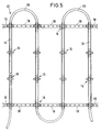
- FIG. 1 is a plan view of a section of a Endless grating 10 shown.
- the holding grid 10 has several groups 12 of several (in this case 3) fixing rods 14, which are in axial extension to each other are arranged.
- the fixing rods are with at their ends Node elements 16 connected, the outer ones Fixing rods 14 of each group 12 at their free ends also have a node element 16.
- These node elements 16 at the free ends of the outer fixing rods 14 are by spacer bars 18 with each other connected.
- FIG. 1 shown regular lattice structure, at the top and at the lower end in the respective axial alignment spacer rods 18 arranged with one another with transversely between these extending fixing rods 14 are arranged.
- a such retaining grid tape can be rolled up, and that is, even if there is a serpentine line on the retaining grid belt bent pipe is clipped on. This will still to be discussed in connection with FIG. 5.
- each node element 16 according to FIG. 3 is included provided a base plate 20, from the bottom thereof 4 locking buttons 22 protrude, each in pairs are arranged opposite, the two pairs are rotated 90 ° against each other (see also Fig. 4).
- a base plate 20 from the bottom thereof 4 locking buttons 22 protrude, each in pairs are arranged opposite, the two pairs are rotated 90 ° against each other (see also Fig. 4).
- the tube 32 is made of plastic, especially cross-linked polyethylene, and has straight lines Sections 34 and sections 36 bent by 180 ° in each case on. While the rectilinear sections 34 are parallel to the fixing rods 14, the bent Sections 36 on the opposite sides of the upper and lower spacer bars 18 and thus over the upper and lower boundary edges of the holding grid 10 about.
- the tube 32 is in the tube receptacles 26 of the node elements 16 and is inserted by more than 180 ° closed protrusions 24 against inadvertent slipping out of the pipe receptacles 26 held.
- An endless holding grille 10 that has an endless Snake-shaped tube 32 according to FIG. 5 is equipped, can be wound up and in this form Transport construction site where it is handled and is cut to length if necessary.
- Fig. 6 The flexibility when laying such a tube module is shown in Fig. 6. Due to a in Fig. 6 38 indicated area to be provided with the tube 32 Area 40 is required by the regular serpentine course of the tube 32 to deviate in certain areas.
- This can be very simple Be achieved by the grille 10 by two or several successive groups of fixing rods 14 separating spacer rods 18 separated become.
- the two spacer rods 18 to be removed are located at opposite ends a fixing rod group 12 and extend to different Sides of this. This way arise three successive groups 12 of fixing rods 14, each with only one spacer bar 18 are connected, these two spacer bars 18 on mutual ends, namely at the upper and lower End of the holding grid 10 are arranged.
- the area 38 the area 40 also requires that the Fixing rods 14 and the spacer rods 18 in this area from their originally perpendicular to each other directional deviations. This will do so realized that either the rigid connections of the Bars 14 and 18 with the node elements 16 lifted are to these rods 14 and 18 then articulated with the To connect node elements 16.
- the choice of connections of node elements 16 and rods 14 and 18, which as articulated connections should be made so that the Pipe 32 around area 38 can hang on the size of the area 38 and its shape.
- fixing rods 14 within each group 12 and the Spacer bars 18 with the node elements 16 optionally can be connected rigidly or articulated a high degree of flexibility, which is the course of the laying pipe 32 and in particular what the deviation of the pipe run 32 from the regular serpentine shape 5 concerns.
Landscapes
- Engineering & Computer Science (AREA)
- Physics & Mathematics (AREA)
- Thermal Sciences (AREA)
- Chemical & Material Sciences (AREA)
- Combustion & Propulsion (AREA)
- Mechanical Engineering (AREA)
- General Engineering & Computer Science (AREA)
- Supports For Pipes And Cables (AREA)
- Steam Or Hot-Water Central Heating Systems (AREA)
Abstract
Description
- mehreren jeweils zueinander parallelen Fixierstäben mit Halteelementen zum Halten des Rohres und
- mehreren die Fixierstäbe kreuzenden Abstandsstäben, die zwischen jeweils benachbarten Fixierstäben verlaufen und mit diesen verbunden und/oder verbindbar sind.
- Fig. 1
- eine Draufsicht auf ein Haltegitter gemäß einer bevorzugten Ausführungsform der Erfindung,
- Fig. 2
- eine vergrößerte Darstellung eines Abstandsstabes,
- Fig. 3
- einen Schnitt entlang der Linie III-III der Fig. 1 durch ein Knotenelement,
- Fig. 4
- eine Draufsicht auf ein Knotenelement des Haltegitters gemäß Fig. 1 in vergrößertem Maßstab,
- Fig. 5
- eine Darstellung ähnlich der gemäß Fig. 1, jedoch mit auf dem Haltegitter angeordnetem und schlangenlinienförmig verlaufendem Rohr und
- Fig. 6
- ein Beispiel für eine Veränderung der Haltegitterstruktur zum Verlegen des von diesem gehaltenen Rohres um ein "Hindernis" herum.
Claims (16)
- Haltegitter zum Halten eines Rohres für eine Flächenheizung oder Flächenkühlung mit gebogenen und geradlinigen Abschnitten, mitmehreren jeweils zueinander parallelen Fixierstäben (14) mit Halteelementen (24) zum Halten des Rohres (32) undmehreren die Fixierstäbe (14) kreuzenden Abstandsstäben (18), die zwischen jeweils benachbarten Fixierstäben (14) verlaufen und mit diesen verbunden und/oder verbindbar sind.
- Haltegitter nach Anspruch 1, dadurch gekennzeichnet, daß die Abstandsstäbe (18) zumindest mit einigen der Fixierstäbe (14) gelenkig verbunden und/oder verbindbar sind.
- Haltegitter nach Anspruch 1 oder 2, dadurch gekennzeichnet, daß die Abstandsstäbe (18) zumindest mit einigen der Fixierstäbe (14) lösbar verbunden sind.
- Haltegitter nach einem der Ansprüche 1 bis 3, dadurch gekennzeichnet, daß mehrere Fixierstäbe (14) gelenkig miteinander verbunden und/oder verbindbar sind.
- Haltegitter nach einem der Ansprüche 1 bis 4, dadurch gekennzeichnet, daß die Halteelemente (24) als Knotenelemente (16) ausgebildet sind, mit denen Fixierstäbe (14) und/oder Abstandsstäbe (18) verbunden sind.
- Haltegitter nach Anspruch 5, dadurch gekennzeichnet, daß jedes Knotenelement (16) eine Basisplatte (20) mit von dieser abstehenden Halteelementen (24) zum klemmenden Halten des Rohres (32) und Rastverbindungsvorsprüngen (22) zum rastenden Verbinden mit den Fixierstäben (14) und/oder den Abstandsstäben (18) aufweist.
- Haltegitter nach Anspruch 6, dadurch gekennzeichnet, daß die Fixierstäbe (14) und/oder die Abstandsstäbe (18) zumindest an ihren Enden Rastlöcher (28;30) zum Aufstecken auf die Rastverbindungsvorsprünge (22) der Knotenelemente (16) aufweisen.
- Haltegitter nach Anspruch 6 oder 7, dadurch gekennzeichnet, daß die Basisplatte (20) 2 Paare von entlang einer geraden Ausrichtlinie angeordneten und voneinander beabstandeten Rastverbindungsvorsprünge (22) aufweist, wobei die Ausrichtlinien der beiden Paare von Rastverbindungsvorsprüngen (22) quer zueinander verlaufen.
- Haltegitter nach Anspruch 8, dadurch gekennzeichnet, daß der Abstand der Rastverbindungsvorsprünge (22) untereinander für jedes Paar gleich ist.
- Haltegitter nach Anspruch 7 und 8 oder 9, dadurch gekennzeichnet, daß die Fixierstäbe (14) und/oder die Abstandsstäbe (18) an ihren Enden jeweils 2 Rastlöcher (28;30) aufweisen, deren Abstände gleich den Abständen der Rastverbindungsvorsprünge (22) eines Paars des Knotenelements (16) sind.
- Haltegitter nach einem der Ansprüche 7 bis 10, dadurch gekennzeichnet, daß die Fixierstäbe (14) und/oder die Abstandsstäbe (18) mehrere Rastlöcher (28;30) aufweisen, die zumindest entlang von Teillängsabschnitten der Stäbe (14;18) gleichmäßig aufeinander folgend angeordnet sind.
- Haltegitter nach einem der Ansprüche 1 bis 11, dadurch gekennzeichnet, daß die Fixierstäbe (14) und/oder die Abstandsstäbe (18) Sollbruchstellen zum Kürzen ihrer Längen aufweisen.
- Haltegitter nach einem der Ansprüche 1 bis 12, dadurch gekennzeichnet, daß die Stäbe (14,18), die Halteelemente (24) und, sofern vorhanden, die Knotenelemente (16) aus Kunststoff oder Metall bestehen.
- Haltegitter nach Anspruch 5 oder einem auf Anspruch 5 rückbezogenen Anspruch, dadurch gekennzeichnet, daß mehrere Gruppen (12) aus jeweils mindestens 2 in Verlängerung zueinander angeordneten und miteinander durch Knotenelemente (16) verbundenen Fixierstäben (14) vorgesehen sind und daß die jeweils außenliegenden Fixierstäbe (14) benachbarter Gruppen (12) mit Knotenelementen (16) verbunden sind, mit denen wiederum jeweils ein Abstandsstab (18) verbunden ist.
- Flexibles Rohrverlegeelement mit einem Haltegitter (10) nach einem der vorhergehenden Ansprüche und einem an den Halteelementen (24) des Haltegitters (10) gehaltenen Rohr (32) mit geradlinigen Abschnitten (34) und gebogenen Abschnitten (36).
- Rohrverlegeelement nach Anspruch 15, dadurch gekennzeichnet, daß das Haltegitter (10) gemäß Anspruch 14 ausgebildet ist und daß das Rohr (32) schlangenlinienförmig verläuft, wobei seine geradlinigen Abschnitte (34) jeweils entlang der Fixierstäbe (14) verlaufen sowie an den Knotenelementen (16) gehalten sind und seine gebogenen Abschnitte (36) über die Abstandsstäbe (18) überstehen.
Applications Claiming Priority (2)
| Application Number | Priority Date | Filing Date | Title |
|---|---|---|---|
| DE19735258A DE19735258C2 (de) | 1997-08-14 | 1997-08-14 | Haltegitter zum Halten eines Rohres für eine Flächenheizung oder Flächenkühlung mit gebogenen und geradlinigen Abschnitten |
| DE19735258 | 1997-08-14 |
Publications (2)
| Publication Number | Publication Date |
|---|---|
| EP0897089A2 true EP0897089A2 (de) | 1999-02-17 |
| EP0897089A3 EP0897089A3 (de) | 2000-12-27 |
Family
ID=7838969
Family Applications (1)
| Application Number | Title | Priority Date | Filing Date |
|---|---|---|---|
| EP98115340A Withdrawn EP0897089A3 (de) | 1997-08-14 | 1998-08-14 | Haltegitter zum Halten eines Rohres für eine Flächenheizung oder Flächen-kühlung mit gebogenen und geradlinigen Abschnitten |
Country Status (2)
| Country | Link |
|---|---|
| EP (1) | EP0897089A3 (de) |
| DE (1) | DE19735258C2 (de) |
Cited By (2)
| Publication number | Priority date | Publication date | Assignee | Title |
|---|---|---|---|---|
| EP1043548A3 (de) * | 1999-04-08 | 2003-01-29 | Fischerwerke Arthur Fischer GmbH & Co. KG | Montageelement zur Befestigung von Wandheizungsmodulen |
| WO2012143316A1 (de) * | 2011-04-21 | 2012-10-26 | Basf Se | Vorrichtung zur befestigung von wärmeträgerleitungen an einem behälter |
Families Citing this family (1)
| Publication number | Priority date | Publication date | Assignee | Title |
|---|---|---|---|---|
| DE29910425U1 (de) | 1999-06-15 | 1999-10-28 | Reckzeh, Manfred, 63457 Hanau | Wand- oder Deckenvorbau mit integrierter Raumheizungs- bzw. Kühlungsanlage und Halterung hierfür |
Family Cites Families (3)
| Publication number | Priority date | Publication date | Assignee | Title |
|---|---|---|---|---|
| DE7907228U1 (de) * | 1979-03-15 | 1979-08-30 | Hugo Fibelkorn Kunststofftechnik Formen- Und Werkzeugbau, 5628 Heiligenhaus | Traegermatte fuer die wasserrohre einer fussbodenheizung |
| DE3228112A1 (de) * | 1982-07-28 | 1984-02-09 | Kellner Gmbh & Co Kg, 4514 Ostercappeln | System zur verlegung und fixierung der heizungsrohre von flaechenheizungen |
| DE3513971A1 (de) * | 1985-04-18 | 1986-10-30 | I.G. Bauerhin GmbH elektro-technische Fabrik, 6466 Gründau | Montagegitter fuer die in der regel abstandsgleiche fixierung des heizdrahtes bzw. der daraus gebildeten heizschleifen |
-
1997
- 1997-08-14 DE DE19735258A patent/DE19735258C2/de not_active Expired - Fee Related
-
1998
- 1998-08-14 EP EP98115340A patent/EP0897089A3/de not_active Withdrawn
Cited By (2)
| Publication number | Priority date | Publication date | Assignee | Title |
|---|---|---|---|---|
| EP1043548A3 (de) * | 1999-04-08 | 2003-01-29 | Fischerwerke Arthur Fischer GmbH & Co. KG | Montageelement zur Befestigung von Wandheizungsmodulen |
| WO2012143316A1 (de) * | 2011-04-21 | 2012-10-26 | Basf Se | Vorrichtung zur befestigung von wärmeträgerleitungen an einem behälter |
Also Published As
| Publication number | Publication date |
|---|---|
| DE19735258C2 (de) | 1999-09-30 |
| DE19735258A1 (de) | 1999-02-25 |
| EP0897089A3 (de) | 2000-12-27 |
Similar Documents
| Publication | Publication Date | Title |
|---|---|---|
| DE19815047B4 (de) | Anordnung zur schraubenlosen Verbindung von Gitterkabelbahnen | |
| DE69304416T2 (de) | Selbstverrastende Kabelrinnenteilstücke und Herstellungsverfahren | |
| DE8019598U1 (de) | Klammer zum Befestigen von Fußboden-Heizungsrohren | |
| DD297497A5 (de) | Energiefuehrungskette | |
| EP0049529B1 (de) | Abstandhalter zur Abstützung von Baustahlmatten | |
| DE69416544T2 (de) | Packung und Verfahren zur Fertigung einer Packung | |
| DE19735258C2 (de) | Haltegitter zum Halten eines Rohres für eine Flächenheizung oder Flächenkühlung mit gebogenen und geradlinigen Abschnitten | |
| DE202021105966U1 (de) | Abstandhalterleiste | |
| DE3513971A1 (de) | Montagegitter fuer die in der regel abstandsgleiche fixierung des heizdrahtes bzw. der daraus gebildeten heizschleifen | |
| EP0669424B1 (de) | Abstandshalter zum Festlegen der Fugenbreite | |
| DE102005039648A1 (de) | Positioniermittel, Verfahren zur Herstellung und zur Einbringung eines Positioniermittels | |
| DE4340312C2 (de) | Vorrichtung zur Halterung von Rohren | |
| EP4495532B1 (de) | Gewellte gittermatte | |
| DE19713738C1 (de) | Gitterartiges Deckenelement als Kühleinrichtung | |
| DE4444915C1 (de) | Haltevorrichtung zum Festlegen eines strangförmigen Bauteils, insbesondere eines Rohres | |
| DE8528318U1 (de) | Hängedeckeneinheit | |
| EP0694748A1 (de) | Verlegbare Rohranordnung | |
| DE3321758C2 (de) | Halteleiste für im Abstand voneinander zu verlegende Rohre | |
| AT9591U1 (de) | Kanalsystem | |
| CH658092A5 (de) | Bausatz zum erstellen einer abhaengbaren rasterdecke. | |
| DE2712702B1 (de) | Vorrichtung zur Festlegung von Einbauplatten in Berieselungseinbauten von Waermetauschern | |
| EP1373772B1 (de) | Befestigungsvorrichtung zum befestigen eines rohres oder einer rohranordnung zwischen bewehrungslagen einer betonplatte | |
| DE8228747U1 (de) | Rost zur begehbaren abdeckung von rinnen, becken, gruben oder als fussabtreter | |
| DE9012733U1 (de) | Putzträger | |
| DE2206362C3 (de) | Be- und Entlüftung für ein Kaltdach |
Legal Events
| Date | Code | Title | Description |
|---|---|---|---|
| PUAI | Public reference made under article 153(3) epc to a published international application that has entered the european phase |
Free format text: ORIGINAL CODE: 0009012 |
|
| AK | Designated contracting states |
Kind code of ref document: A2 Designated state(s): AT BE CH CY DE DK ES FI FR GB GR IE IT LI LU MC NL PT SE |
|
| AX | Request for extension of the european patent |
Free format text: AL;LT;LV;MK;RO;SI |
|
| PUAL | Search report despatched |
Free format text: ORIGINAL CODE: 0009013 |
|
| AK | Designated contracting states |
Kind code of ref document: A3 Designated state(s): AT BE CH CY DE DK ES FI FR GB GR IE IT LI LU MC NL PT SE |
|
| AX | Request for extension of the european patent |
Free format text: AL;LT;LV;MK;RO;SI |
|
| RAP1 | Party data changed (applicant data changed or rights of an application transferred) |
Owner name: UPONOR INNOVATION AB |
|
| AKX | Designation fees paid | ||
| REG | Reference to a national code |
Ref country code: DE Ref legal event code: 8566 |
|
| STAA | Information on the status of an ep patent application or granted ep patent |
Free format text: STATUS: THE APPLICATION IS DEEMED TO BE WITHDRAWN |
|
| 18D | Application deemed to be withdrawn |
Effective date: 20010628 |