EP0895574B1 - Vorrichtung zum messen räumlicher koordinaten - Google Patents
Vorrichtung zum messen räumlicher koordinaten Download PDFInfo
- Publication number
- EP0895574B1 EP0895574B1 EP97922439A EP97922439A EP0895574B1 EP 0895574 B1 EP0895574 B1 EP 0895574B1 EP 97922439 A EP97922439 A EP 97922439A EP 97922439 A EP97922439 A EP 97922439A EP 0895574 B1 EP0895574 B1 EP 0895574B1
- Authority
- EP
- European Patent Office
- Prior art keywords
- arm
- shaft
- sheath
- assembly
- joint
- Prior art date
- Legal status (The legal status is an assumption and is not a legal conclusion. Google has not performed a legal analysis and makes no representation as to the accuracy of the status listed.)
- Expired - Lifetime
Links
- 238000012546 transfer Methods 0.000 claims abstract description 18
- 239000000523 sample Substances 0.000 claims description 19
- 230000033001 locomotion Effects 0.000 claims description 18
- 238000000429 assembly Methods 0.000 claims description 10
- 230000000712 assembly Effects 0.000 claims description 6
- 238000004891 communication Methods 0.000 claims description 3
- 230000003750 conditioning effect Effects 0.000 claims description 3
- 239000004020 conductor Substances 0.000 abstract description 6
- 238000013459 approach Methods 0.000 abstract description 4
- 230000015556 catabolic process Effects 0.000 abstract description 3
- 238000006731 degradation reaction Methods 0.000 abstract description 3
- NJPPVKZQTLUDBO-UHFFFAOYSA-N novaluron Chemical compound C1=C(Cl)C(OC(F)(F)C(OC(F)(F)F)F)=CC=C1NC(=O)NC(=O)C1=C(F)C=CC=C1F NJPPVKZQTLUDBO-UHFFFAOYSA-N 0.000 description 16
- 230000008878 coupling Effects 0.000 description 9
- 238000010168 coupling process Methods 0.000 description 9
- 238000005859 coupling reaction Methods 0.000 description 9
- 238000013461 design Methods 0.000 description 9
- 230000009977 dual effect Effects 0.000 description 7
- 239000000463 material Substances 0.000 description 7
- OKTJSMMVPCPJKN-UHFFFAOYSA-N Carbon Chemical compound [C] OKTJSMMVPCPJKN-UHFFFAOYSA-N 0.000 description 6
- 238000005259 measurement Methods 0.000 description 6
- 230000003287 optical effect Effects 0.000 description 6
- 150000003071 polychlorinated biphenyls Chemical class 0.000 description 5
- 230000008439 repair process Effects 0.000 description 5
- 125000006850 spacer group Chemical group 0.000 description 5
- 238000000034 method Methods 0.000 description 4
- 230000008901 benefit Effects 0.000 description 3
- 229910052799 carbon Inorganic materials 0.000 description 3
- 229910002804 graphite Inorganic materials 0.000 description 3
- 239000010439 graphite Substances 0.000 description 3
- 230000007246 mechanism Effects 0.000 description 3
- 230000002829 reductive effect Effects 0.000 description 3
- 229910000906 Bronze Inorganic materials 0.000 description 2
- RYGMFSIKBFXOCR-UHFFFAOYSA-N Copper Chemical compound [Cu] RYGMFSIKBFXOCR-UHFFFAOYSA-N 0.000 description 2
- 229910000831 Steel Inorganic materials 0.000 description 2
- XAGFODPZIPBFFR-UHFFFAOYSA-N aluminium Chemical compound [Al] XAGFODPZIPBFFR-UHFFFAOYSA-N 0.000 description 2
- 229910052782 aluminium Inorganic materials 0.000 description 2
- 230000005540 biological transmission Effects 0.000 description 2
- 239000010974 bronze Substances 0.000 description 2
- 230000008859 change Effects 0.000 description 2
- 229910052802 copper Inorganic materials 0.000 description 2
- 239000010949 copper Substances 0.000 description 2
- KUNSUQLRTQLHQQ-UHFFFAOYSA-N copper tin Chemical compound [Cu].[Sn] KUNSUQLRTQLHQQ-UHFFFAOYSA-N 0.000 description 2
- 230000001419 dependent effect Effects 0.000 description 2
- 238000010586 diagram Methods 0.000 description 2
- 239000003292 glue Substances 0.000 description 2
- 238000012986 modification Methods 0.000 description 2
- 230000004048 modification Effects 0.000 description 2
- 238000012544 monitoring process Methods 0.000 description 2
- 238000000275 quality assurance Methods 0.000 description 2
- 239000010959 steel Substances 0.000 description 2
- DCPDZFRGNJDWPP-UHFFFAOYSA-N 1,2,3,4,5-pentachloro-6-(2,4,5-trichlorophenyl)benzene Chemical compound C1=C(Cl)C(Cl)=CC(Cl)=C1C1=C(Cl)C(Cl)=C(Cl)C(Cl)=C1Cl DCPDZFRGNJDWPP-UHFFFAOYSA-N 0.000 description 1
- JDZUWXRNKHXZFE-UHFFFAOYSA-N 1,2,3,4,5-pentachloro-6-(2,4,6-trichlorophenyl)benzene Chemical compound ClC1=CC(Cl)=CC(Cl)=C1C1=C(Cl)C(Cl)=C(Cl)C(Cl)=C1Cl JDZUWXRNKHXZFE-UHFFFAOYSA-N 0.000 description 1
- VXXBCDUYUQKWCK-UHFFFAOYSA-N 1,2,3,4,5-pentachloro-6-(3,4,5-trichlorophenyl)benzene Chemical compound ClC1=C(Cl)C(Cl)=CC(C=2C(=C(Cl)C(Cl)=C(Cl)C=2Cl)Cl)=C1 VXXBCDUYUQKWCK-UHFFFAOYSA-N 0.000 description 1
- JPOPEORRMSDUIP-UHFFFAOYSA-N 1,2,4,5-tetrachloro-3-(2,3,5,6-tetrachlorophenyl)benzene Chemical compound ClC1=CC(Cl)=C(Cl)C(C=2C(=C(Cl)C=C(Cl)C=2Cl)Cl)=C1Cl JPOPEORRMSDUIP-UHFFFAOYSA-N 0.000 description 1
- CUGLICQCTXWQNF-UHFFFAOYSA-N 1,2-dichloro-3-(2,6-dichlorophenyl)benzene Chemical group ClC1=CC=CC(C=2C(=CC=CC=2Cl)Cl)=C1Cl CUGLICQCTXWQNF-UHFFFAOYSA-N 0.000 description 1
- 235000011960 Brassica ruvo Nutrition 0.000 description 1
- 239000004593 Epoxy Substances 0.000 description 1
- 230000002411 adverse Effects 0.000 description 1
- 238000010276 construction Methods 0.000 description 1
- 238000005260 corrosion Methods 0.000 description 1
- 230000007797 corrosion Effects 0.000 description 1
- 238000005520 cutting process Methods 0.000 description 1
- 230000001934 delay Effects 0.000 description 1
- 239000000835 fiber Substances 0.000 description 1
- 230000006870 function Effects 0.000 description 1
- 238000011065 in-situ storage Methods 0.000 description 1
- 230000001939 inductive effect Effects 0.000 description 1
- 239000011810 insulating material Substances 0.000 description 1
- 230000003993 interaction Effects 0.000 description 1
- 230000000670 limiting effect Effects 0.000 description 1
- 238000003754 machining Methods 0.000 description 1
- 238000004519 manufacturing process Methods 0.000 description 1
- 238000001465 metallisation Methods 0.000 description 1
- 230000036961 partial effect Effects 0.000 description 1
- 230000008569 process Effects 0.000 description 1
- 230000000135 prohibitive effect Effects 0.000 description 1
- 230000001681 protective effect Effects 0.000 description 1
- 230000009467 reduction Effects 0.000 description 1
- 230000008054 signal transmission Effects 0.000 description 1
- 229910052709 silver Inorganic materials 0.000 description 1
- 239000004332 silver Substances 0.000 description 1
Images


Classifications
-
- H—ELECTRICITY
- H01—ELECTRIC ELEMENTS
- H01R—ELECTRICALLY-CONDUCTIVE CONNECTIONS; STRUCTURAL ASSOCIATIONS OF A PLURALITY OF MUTUALLY-INSULATED ELECTRICAL CONNECTING ELEMENTS; COUPLING DEVICES; CURRENT COLLECTORS
- H01R39/00—Rotary current collectors, distributors or interrupters
- H01R39/02—Details for dynamo electric machines
- H01R39/08—Slip-rings
-
- G—PHYSICS
- G01—MEASURING; TESTING
- G01B—MEASURING LENGTH, THICKNESS OR SIMILAR LINEAR DIMENSIONS; MEASURING ANGLES; MEASURING AREAS; MEASURING IRREGULARITIES OF SURFACES OR CONTOURS
- G01B5/00—Measuring arrangements characterised by the use of mechanical techniques
- G01B5/004—Measuring arrangements characterised by the use of mechanical techniques for measuring coordinates of points
- G01B5/008—Measuring arrangements characterised by the use of mechanical techniques for measuring coordinates of points using coordinate measuring machines
-
- H—ELECTRICITY
- H01—ELECTRIC ELEMENTS
- H01R—ELECTRICALLY-CONDUCTIVE CONNECTIONS; STRUCTURAL ASSOCIATIONS OF A PLURALITY OF MUTUALLY-INSULATED ELECTRICAL CONNECTING ELEMENTS; COUPLING DEVICES; CURRENT COLLECTORS
- H01R35/00—Flexible or turnable line connectors, i.e. the rotation angle being limited
- H01R35/02—Flexible line connectors without frictional contact members
Definitions
- This invention relates to measuring devices, and more particularly to articulated arm coordinate measuring machines for measuring three-dimensional objects.
- the probe can be manipulated to reach any point in space within substantially a sphere centered on the base of the arm. This is called the measurement sphere of the machine. Any article being measured must therefore lie within the measurement sphere.
- a critical step in the measurement process is determining the position of each of the joints at a given instant in time.
- the joints are broken down into singular rotational degrees of freedom, each of which is measured using a dedicated rotational transducer.
- Each transducer outputs an electrical signal which varies according to the movement of the joint in that degree of freedom.
- the signal is carried on wires through the arm to the recorder/analyzer.
- the transducers be mechanically coupled to the joint as directly as possible. This usually requires that the transducers be incorporated into the joints of the arm.
- each encoder measures the rotational position of its axle by coupling is movement to a pair of internal wheels having successive transparent and opaque bands. Light is shined through the wheels onto optical sensors which feed a pair of electrical outputs. As the axle sweeps through an arc, the output of the analog encoder is substantially two sinusoidal signals which are 90 degrees out of phase. Coarse positioning occurs through monitoring the change in polarity of the two signals. Fine positioning is determined by measuring the actual value of the two signals at the instant in question. Maximum accuracy is obtained by measuring the output precisely before it is corrupted by electronic noise.
- a problem with prior designs involves a loss in precision due to signal degradation as the signal is transmitted down wires to the recorder/analyzer. A machine which minimizes signal degradation is therefore preferable.
- the structures employed to restrict this motion are in the form of single or multiply "stacked" end-stops.
- Each "stack" of end-stops ideally allows up to 360 degrees of motion before stopping.
- it has been found that using more than one or two stacks increases cost and/or reduces precision to the point of being prohibitive.
- US Patent 5148377 disposes a co-ordinate system with two rotatable joints with one degree of freedom.
- US Patent 3944798 relates to the measurement of object positions.
- European Patent Application 0331914 relates to a robot gripper with slip-rings.
- European Patent Application 0730210 discloses a co-ordinate system with multiple joints of very limited movement.
- US Patent 4937759 describes a measuring arm with wire connections limiting movement of joints.
- US Patent 4388758 relates to an inductive angle measurement device with a rotor/stator and single slip-ring.
- the present invention provides an arm as defined in Claim 1.
- the arm may include the features of any one or more of dependent Claims 2 to 9.
- the principal and secondary objects of this invention are to provide an inexpensive, lightweight, high precision, sleek profile coordinate measuring arm which offers unrestricted probe motion from any given orientation.
- a multi-jointed arm having: 1) swiveling joints which are unlimited by one or more end-stops; 2) signal conditioning means closely located to the joint position transducers; and 3) stable transfer members which comprise a freely rotating shaft mounted within an outer sheath, wherein both shaft and sheath extend substantially the length of the member.
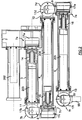
- FIG. 1 a three-dimensional diagrammatic view of the spatial coordinate measuring machine arm 1 according to the invention.
- the arm comprises a stationary support base 2, three rigid transfer members 3, 4, 5 and a probe 6 which are interconnected with a plurality of joints 7a, 7b, 7c, 7d, 7e, 7f.
- Each of the joints is dedicated to a single degree of freedom and allows rotational movement about a dedicated axis 10a-10f which is fixed relative to that joint.
- the joints can be divided into two categories, namely: 1) those joints 7a, 7c, 7e which allow the swiveling motion associated with a specific member (hereinafter, “swiveling joints”), and 2) those joints 7b, 7d, 7f which allow a change in the relative angle formed between two adjacent members or between the probe and its adjacent member (hereinafter, “hinge joints”).
- swiveling joints those joints 7a, 7c, 7e which allow the swiveling motion associated with a specific member
- joints 7b, 7d, 7f which allow a change in the relative angle formed between two adjacent members or between the probe and its adjacent member
- Each of two pairs of joints 7b, 7c and 7d, 7e, are connected via a yoke, 8 and 9 respectively.
- Each hinge joint 7b, 7d, 7f is connected to its adjacent transfer member 3, 4, 5 by means of a pedestal 11, 12, 13, respectively.
- the pedestal precisely orients the rotational axis of its hinge joint orthogonally to the major axis of its adjacent transfer member.
- the swiveling joints 7a, 7c, 7e are unlimited in their range of motion. This capability is accomplished without using any "stack" type structures described earlier. This is in stark contrast to prior designs.
- the preferred hinge joints 7b, 7d, 7e are limited by interference between adjacent members. Although this interference is not required, as shown by Raab ( U.S. Patent No. 5,402,582 ), which utilizes offset or skewed adjacent members; it has been found that the preferred approach offers a symmetrical design without sacrificing rigidity, and a sleeker profile which more conveniently allows access through narrower passageways. Non-symmetrical designs must cope with greater momentary forces generated by the orthogonally arranged members.
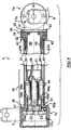
- Figure 2 shows cross-sectional view of the preferred coordinate measuring arm.
- Six joints 7a-7f are connected by three transfer members 3-5, two yokes 8, 9, and three pedestals 11-13.
- the invention is able to achieve unlimited motion in the swiveling joints by eliminating the need for a continuous, flexible wire running between the joints straddling a swiveling joint.
- the preferred means for conducting power and signals through these joints replaces wires with a multi-conductor electrical slip-ring sub-assembly. Therefore, there is a slip-ring sub-assembly 14, 15, 16 operatively associated with each swiveling joint 7a, 7c, 7e.
- the slip-ring sub-assembly will be described in detail later.
- Each hinge or swiveling joint has its own dedicated motion transducer in the form of an optical encoder 17a-17f.
- Hinge joint encoders 17b, 17d and 17f are shown hidden in Figure 2 . Since each encoder forms an integral part of each joint by providing primary rotational bearings, it is important that the encoder be structurally rugged.
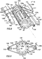
- a encoder 17c comprises a generally cylindrical body 20 having an outer housing comprising a cup-shaped casing 21 and a circular face plate 22.
- a central axle 23 is rotatively mounted to the body on internal bearings and extends through the face plate.
- An electrical cable 24 carries power to the encoder and output signals from the encoder through an aperture 25 in the housing.
- the preferred encoder is a ROD 450.0000 - 5000 model analog optical encoder available from Heidenhain of Traunrent, Germany. These encoders offer structural ruggedness by having a large central axle and bearing. Ideally, this encoder is capable of resolutions of about 5000 cycles per revolution.
- Digital encoders are available and could be used in the invention; however, currently available designs are not preferred. Some "digital" encoders which use simple clipping circuits to generate a square, rather than sine wave output, suffer from inferior resolution. True digital encoders having onboard digitizing circuitry currently suffer from being too bulky. However, as circuit board sizes decrease, adequate encoders may become available. Current digital encoders are also more expensive and less versatile with respect to the type of systems they are capable of interfacing.
- the encoder housing forms part of the outer surface of the arm, slight modifications to the encoders may be required. Power and output wires should not be exposed and should therefore run through portions of the housing having contact with internal cavities of the arm. Means for mounting the encoders to the arm may require additional modifications, however, preferred mounting occurs primarily through screw attachment to the structurally rugged face plate.
- Each transfer member 4 is in the form of a dual concentric tubular structure having an inner tubular shaft 30 rotatively mounted coaxially within an outer tubular sheath 31 by means of a first bearing 32 mounted proximately to a first end of the member 4 adjacent to a hinge joint 7d, and a second bearing comprising a slip-ring sub-assembly 15 in combination with the encoder 17c of an adjacent swiveling joint 7c located at an opposite end of the member.
- the shaft 30 is mounted to the hinge joint 7d by fastening means such as nut and screws 33 connecting the shaft end flange 34 to base plate 35 of pedestal 12.
- the sheath 31 is mounted to the swiveling joint 7c by fastening means such as nut and screws 36 connecting the sheath end flange 37 to the yoke 8.
- the amount of axis misalignment between encoder and the swiveling shaft are kept to a minimum, thereby increasing precision.
- the shaft 30 comprises a rigid cylindrical tubular body 40 having opposite ends to which are bonded first and second end-caps 41, 42.
- the end-caps are glued to the body in such a way that the resulting member is precisely and accurately balanced.
- the preferred method of assuring this balance involves allowing the glue to cure while the assembled member is being revolved.
- the sheath 31 comprises a rigid tubular body 43 having similarly attached first and second end-caps 44,45.
- first end-cap 42 of the shaft 30 provides an outer surface for mounting the first bearing 32, and a flange 34 for attachment to the pedestal 12.
- first end-cap 45 of the sheath 31 has female coupling flange 47 for engaging the outer surface of the first bearing 32.
- the second end-cap 41 of the shaft 30 is integral with the central axle 50 of the slip-ring sub-assembly 15 dedicated to swiveling joint 7c.
- An access hole 51 extends through a side wall of both the sheath 31 and the second end-cap 44 of the sheath to allow for the loosening of the split collar clamp 53 which firmly couples the central axle 50 of the slip-ring to the swiveling joint encoder axle 23. This allows for quick decoupling during repair or reconfiguration.
- the end-caps are preferably made from an easily machinable, inexpensive, light-weight, rigid material such as aluminum.
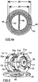
- cylindrical tubes for both sheath and shaft are preferred because they offer construction simplicity, rigidity, light weight, and space inside for the printed circuit board 46 feature of the invention. Also, as shown in Figure 4a , they allow a concentric mounting of a shaft tubular body 40 having an outer diameter 48 approaching the inner diameter 49 of the sheath tubular body 43, thereby increasing rigidity while maintaining low weight and a sleek profile. Therefore, the shaft tubular body outer diameter is preferably at least 50%, and most preferably at least 75% of the inner diameter of the sheath tubular body.
- the closeness of these two diameters is limited by the interposition of the sheath's first end-cap 45 between the diameters.
- the end-cap could be designed to bond with the outer surface of the sheath body, thereby allowing the two diameters to be closer, it has been found that the preferred design is less expensive with respect to machining tolerances while maintaining adequate rigidity.
- the tubes are preferably made from a light-weight, rigid material such as epoxy bonded carbon graphite which inexpensively offers a strength to weight ratio in excess of that of steel.
- a light-weight, rigid material such as epoxy bonded carbon graphite which inexpensively offers a strength to weight ratio in excess of that of steel.
- carbon graphite Another advantage of carbon graphite is that it has a low thermal expansion coefficient.
- the shaft and sheath may be made from lighter, inexpensive, and easily machined material such as aluminum, or the preferred carbon graphite.
- a lighter overall arm provides less operator fatigue, reducing the need for complex counterbalances or springs which may reduce precision.
- the invention can be easily modified to incorporate counterbalance mechanisms. Also, the amount play or backlash inherent in a coupled system is significantly reduced by having direct coupling between the various components.
- Each of the dual projection yokes 8, 9 comprises a fork structure with a base 60 and dual support projections 61 and 62.
- the base 60 is mounted to the face plate of the encoder 17e of a swiveling joint using fastening screws 69.
- Each support projection mounts to the pivoting axle of an adjacent hinge joint by means of a releasable stock-type split clamp 63,64, each having a hole 65,66 sized to allow engagement with the axle. The tightness of the clamp is adjusted by end screws 67,68.
- Each pedestal 11, 12, 13 comprises a circular base plate 35 which mounts to the first end-cap 42 of a member shaft using fastening means such as nuts and screws 33.
- the base plate 35 is integral with two parallel, facing circular coupling plates 70, 71 spaced apart to allow for the placement of an encoder between them.
- Each coupling plate comprises a stock-type split clamp 70a, 71a for mounting bearings 75, 76. The tightness of the clamp is adjusted by end screws which engage the lower portions of the plates through recesses 70b, 71b.
- One coupling plate 71 attaches directly to the encoder's face plate 22a using screw fastening means 73.
- the first bearing 76 allows the encoder axle 23a to freely rotate with respect to the pedestal.
- the other coupling plate 70 supports the encoder 17d from the back using an O-ring spacer 74 contacting the encoder and a bearing 75 mounted to the coupling plate.
- the second bearing 75 allows a dummy axle 77 to freely rotate with respect to the pedestal.
- the dummy axle 77 and the encoder axle 23a form the pivoting axle for this hinge joint.
- Protective end-guards 78, 79 are attached to the axles using screw fastening means.
- the pedestal 12 also provides a bracket 80 for mounting the printed circuit board 46 of the hinge joint's adjacent member.
- Wiring 83 soldered to the circuit board 46 passes to the encoder 17d through an opening 81 in the base plate 35 and an O-ring type bushing 82 traversing the space between the encoder and pedestal.
- Wiring 58 between the printed circuit board (PCB) 46 and its adjacent slip-ring sub-assembly connects to the PCB using an electrical connector 59 common in the art.
- a similar yoke and pedestal connects joints 7b and 7c.
- a yoke having encoder straddling dual projections, although not necessary, is preferred because it strengthens the joint making it less susceptible to moment forces acting on the joint.
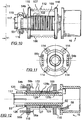
- slip-ring sub-assembly A preferred slip-ring sub-assembly will now be described in detail with reference to Figures 4 and 8-12 .
- Electrical signals are transmitted through the swiveling joints using a slip-ring sub-assembly 16.
- Each slip-ring sub-assembly comprises a central cylindrical shaft or axel 50 along which has been mounted a plurality of cylindrical contact rings 102 each made of copper, bronze or other inexpensive electrically conductive material. The material need not be especially durable because of the light loading and low rate of revolution to which the sub-assembly will be subjected.
- Adjacent contact rings are separated from each other by spacers 103 of insulating material.
- Each contact ring has a central, V-shaped groove 104 embedded circumferentially around its outer surface.
- the groove is sized to provide tracking and electrical contact for a portion of a contact wire 105b stretched transversely across the contact ring.
- the contact wire is made from an electrically conductive, ductile, corrosion resistant and somewhat strong material. The preferred material is silver because of its availability and positive wear characteristics when contacting copper or bronze.
- Each wire is in the form of a loop mounted on two prongs 106, 107 of a support rack which straddles the contact ring and axle combination. Therefore, each wire has first and second portions 108,109 contacting the top and bottom of the contact ring 102.
- the wire is biased toward the ring by means of a spring 110 located on a section of the loop contacting one of the prongs 106 of the support rack.
- the spring portion 111 of the loop is located on the opposite prong 107 so that the spring forces acting on the slip ring are balanced.
- the wires are kept in place by the V-shaped grooves and U-shaped channels 112 set into the surface 113 of the prong facing away from the axle 50.
- the slip-ring axle 50 is rotatively mounted concentrically within a pair of circular support spacers 115, 116 which are each connected to opposite ends of the prongs 106, 107 of the wire loop support rack.
- the spacers are additionally braced by bracing members (removed in Figure 10 ) attached by screw means 114.
- the outer cylindrical surface of each of the support spacers is sized to lodge the slip-ring sub-assembly concentrically within the second end-cap of the sheath.
- the slip-ring sub-assembly 16 is mechanically coupled to a swiveling joint encoder axle by means of a slotted female coupling 117 and a removable split collar clamp 53. This allows for quick decoupling during repair or reconfiguration. Note that the fastening screws 118, 119 of the split collar clamp engage from opposite directions so as to provide balanced axial symmetry, and to allow for screwdriver access from one orientation by simply revolving the axle 50 one-half turn (180 degrees).
- connection between the adjacent swiveling joint 7c and the contact wires 105a, 105b is in the form of two groups of connecting wires, each associated with a mated pair of detachable electrical connectors 54a, 54b, 55a, 55b located on opposite sides of the slip-ring sub-assembly.
- each contact wire loop 105b there is a connecting wire 56b (one for each loop) soldered to the loop at a point proximate to the supporting rack prong 107 which does not contact the spring 110. Therefore, under this arrangement, the connecting wires are divided into two groups. One group (containing 56b ) leads from the loops to the upper connector 54b, and the other group (containing 56a ) leads to the lower connector 55b.
- Electrical connection between the contact rings 102 and a more distal PCB can be in the form of connecting wires 125a-125d (one for each contact ring) running through axial channels 126 in the slip-ring sub-assembly axle 50.
- the channels are provided by a crenellated tube 127 concentrically mounted around the axle 50 beneath the contact rings 102. Electrical contact is made to a ring inserting the end 128a, 128b of a connecting wire into a radial well 129 set into the inner surface of each contact ring.
- the connecting wires 125a-125d congregate at the distal end 130 of the sub-assembly where they bundle into a multi-conductor cable 58 leading to a more distal PCB 46.
- Each preferred slip-ring sub-assembly has nine conductive contact rings 102.
- Analog signals emanating from the encoders are fed via wiring to signal reconditioning units 203, 204, 205 each mounted on a printed circuit board ("PCB") located in the adjacent transfer member more proximate to the base.
- PCBs printed circuit board
- Each of the PCBs residing in a transfer member are sized and dimensioned to fit within the tubular confines of the inner shaft.
- signals from the probe 6 (if there are any) and encoder 17f flow on wiring to PCB 205.
- Signals from encoders 17e and 17d flow to PCB 204.
- signals from encoders 17c and 17b flow to PCB 203.
- Signals from encoder 17a flow to a PCB 202 located on the base 2.
- Each circuit board comprises microprocessor means for reconditioning the analog signals from the encoders into digital information to be sent to the recording and analysis system.
- the PCBs therefore, are capable of receiving and digitizing analog data from their dedicated encoders or probe, and communicating with the recorder/analyzer.
- Fine positioning occurs only when the microprocessor receives a latching signal 301 from the recorder/analyzer.
- a latching signal may be caused by any number of events such as the operator pushing a button on the probe or events generated by the recorder/analyzer software.
- a latching signal 301 causes the microprocessor on each of the PCBs to initiate a fine positioning reading of all the encoders in sync at a specific instant in time.
- the precise voltage from each of the signals of each encoder is digitized and combined with the counter to derive a digitized fine position data word which is stored in the microprocessor until it can transmit its data to the recorder/analyzer.
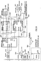
- two lines are devoted to ground 302, and another 305 as a shield.
- Two lines 303 supply power at +10 volts DC to the microprocessors, their attendant circuitry and the encoders. Double lines are used increase reliability and to divide power supply currents. This allows for the use of lighter gauge and hence lighter weight and more flexible wiring.
- Another line 304 supplies +12 volts DC to power the probe 6 if needed.
- One sync line 301 is devoted to carrying the latching signal.
- the two remaining lines are devoted to carrying multiplexed data 310 to and from each of the PCBs. Two lines are used to support the preferred RS-485 data communication standard.
- Analog data from the encoders comprises an index line 321 which signals when the zero position of the encoder is reached, and the two sinusoidal lines A 322 and B323. Comparators 324 effectively transform these signals into square waves monitored by a programmable field programmable gate array (FPGA) logic module 330 thereby tracking the coarse positioning of the encoders.
- the FPGA module also interprets any latching signal arriving on the sync line 301 and directs a voltage hold circuit 325 to initiate a hold of the current voltage outputs of the encoders. The hold circuit maintains this voltage long enough for the programmable microprocessor 340 to digitally sample the held voltage value. Programming for the microprocessor is stored in a memory module 350. Command communication carried on data 326 and address lines 327 between the microprocessor 340, the FPGA 330 and the memory module 350 is routed by a programmable data and address line monitoring unit 360.
- Another advantage of this approach is that it allows the use of fewer electrical connectors (three per member), thereby increasing reliability. Connectors are provided only at one end of the PCB and at the slip-ring sub-assemblies. If data was further multiplexed and/or modulated upon the power lines, fewer connectors may be necessary.
- Another advantage of the present invention is that it allows for modular disassembly and replacement of component parts. For example to replace encoder 17c one would first loosen split collar clamp 53 through holes 51, 52. Next one would remove screws 36 fastening the sheath 31 of member 4 to the yoke 8 of joint 7c. The member 4 would then separate from the joint 7c, and electrical connector pairs 54a, 54b and 55a, 55b would disconnect. Encoder-to-yoke mounting screws 69 would then be exposed. Removing these screws would allow for removal of the encoder save for wiring leading to the circuit board in member 3. Completely removing the encoder 17c would then require cutting the wiring or accessing the circuit board in member 3.
- the slip-ring may be reduced to as few as two conductors, one being the power/signal line, and the other being a ground.
- power and signal transmission means other than a slip-ring may be used.
- electromagnetic transmission through the air may be accomplished using radio waves, microwaves, light waves, or infrared waves.
- Fiber optic cables having swivel connectors may also be adapted for use in the arm.
Landscapes
- Physics & Mathematics (AREA)
- General Physics & Mathematics (AREA)
- Length Measuring Devices With Unspecified Measuring Means (AREA)
- Measuring Pulse, Heart Rate, Blood Pressure Or Blood Flow (AREA)
- Vehicle Body Suspensions (AREA)
- Transmission And Conversion Of Sensor Element Output (AREA)
Claims (9)
- Artikulierter Raumkoordinate-Messarm, welcher aufweist:eine Unterstützungsbasis (2);ein proximales Transfer-Element (3), welches ein proximales Ende und ein distales Ende hat;ein intermediäres Transfer-Element (4), welches ein proximales Ende und ein distales Ende hat;ein distales Transfer-Element (5), welches ein proximales Ende und ein distales Ende hat;eine Sonde (6), welche ein proximales Ende und ein distales Ende hat;eine erste Gelenk-Anordnung (7a), welche schwenkbar das proximale Ende des proximalen Elements mit der Basis verbindet;eine zweite Gelenk-Anordnung (7b, 7c), welche schwenkbar und drehbar das distale Ende des proximalen Elements mit dem proximalen Ende des intermediären Elements verbindet;eine dritte Gelenk-Anordnung (7d, 7e), welche schwenkbar und drehbar das distale Ende des intermediären Elements mit proximalen Ende des distalen Elements verbindet; undeine vierte Gelenk-Anordnung (7f), welche drehbar das proximale Ende der Sonde mit dem distalen Ende des distalen Elements verbindet;dadurch gekennzeichnet,dass jede der ersten, zweiten und dritten Gelenk-Anordnung einen unbegrenzten Bereich einer Schwenk-Bewegung hat und zumindest eine Mehrfach-Kontakt-Gleitring-Teilanordnung (14, 15, 16) aufweist zum Übermitteln von elektrischen Signalen dort hindurch.
- Arm gemäß Anspruch 1, aufweisend Mittel (203, 204, 205), um das Signal von einem Encoder (17b, 17d, 17f) zur Kommunikation mit einer Gleitring-Anordnung (14, 15, 16) und einem Rekorder/Analysator zu digitalisieren.
- Arm gemäß Anspruch 1, wobei die elektrischen Signale Daten aufweisen, welche die Orientierungs-Zustände von Gelenk-Anordnungen reflektieren, welche distaler von der Basis lokalisiert sind als die erste Anordnung.
- Arm gemäß Anspruch 1, wobei jedes der Elemente (3, 4, 5) aufweist:einen inneren röhrenförmigen Schaft (30), welcher ein erstes Ende und ein entgegen gesetztes zweites Ende hat;wobei das erste Ende fest mit einem ersten der Gelenk-Anordnungen bei einem ersten Ende des Schaftes angebracht ist;eine äußere röhrenförmige Umhüllung (31), welche koaxial den inneren röhrenförmigen Schaft umgibt, wobei sich die äußere röhrenförmige Umhüllung axial mit dem inneren röhrenförmigen Schaft gleich ausdehnt, und wobei die Umhüllung eine erste Extremität und eine entgegen gesetzte zweite Extremität hat;wobei die zweite Extremität fest mit einer zweiten der Gelenk-Anordnungen bei einem zweiten Ende des Elements entgegen gesetzt zu dem ersten Ende angebracht ist;ein erstes Lager (32), welches das erste Ende des Schafts proximal zu der ersten Extremität der Umhüllung drehbar montiert; undein zweites Lager (15, 17c), welches das zweite Ende des Schafts proximal zu der zweiten Extremität der Umhüllung drehbar montiert.
- Arm gemäß Anspruch 4, wobei jede der ersten, zweiten und dritten Gelenk-Anordnung (7a-7c) zumindest eine Mehrfach-Kontakt-Gleitring-Teilanordnung zum Übermitteln von elektrischen Signalen dort hindurch aufweist.
- Arm gemäß Anspruch 5, wobei das zweite Lager (15, 17c) eine der Gleitring-Teilanordnungen aufweist.
- Arm gemäß Anspruch 4, wobei:die Umhüllung (31) einen inneren Durchmesser hat;wobei der Schaft (30) einen äußeren Durchmesser hat, welcher zumindest 50 % so groß wie der innere Durchmesser der Umhüllung ist.
- Arm gemäß Anspruch 4, welcher ferner aufweist:Mittel zum Montieren einer ersten Signal-Konditionierungs-Einheit innerhalb des Schaftes.
- Arm gemäß Anspruch 8, wobei die erste Signal-Konditionierungs-Einheit aufweist:Mittel zum Digitalisieren von analogen elektrischen Wellenformen, welche mittels eines Drehbewegungs-Wandlers erzeugt sind, welcher angrenzend an den Schaft lokalisiert ist.
Priority Applications (1)
| Application Number | Priority Date | Filing Date | Title |
|---|---|---|---|
| EP10183916.5A EP2270419B1 (de) | 1996-04-23 | 1997-04-22 | Vorrichtung zum Messen räumlicher Koordinaten |
Applications Claiming Priority (3)
| Application Number | Priority Date | Filing Date | Title |
|---|---|---|---|
| US08/636,590 US5829148A (en) | 1996-04-23 | 1996-04-23 | Spatial measuring device |
| US636590 | 1996-04-23 | ||
| PCT/US1997/006893 WO1997040336A1 (en) | 1996-04-23 | 1997-04-22 | Spatial measuring device |
Related Child Applications (2)
| Application Number | Title | Priority Date | Filing Date |
|---|---|---|---|
| EP10183916.5A Division EP2270419B1 (de) | 1996-04-23 | 1997-04-22 | Vorrichtung zum Messen räumlicher Koordinaten |
| EP10183916.5 Division-Into | 2010-09-30 |
Publications (3)
| Publication Number | Publication Date |
|---|---|
| EP0895574A1 EP0895574A1 (de) | 1999-02-10 |
| EP0895574A4 EP0895574A4 (de) | 2002-06-19 |
| EP0895574B1 true EP0895574B1 (de) | 2012-05-09 |
Family
ID=24552534
Family Applications (2)
| Application Number | Title | Priority Date | Filing Date |
|---|---|---|---|
| EP97922439A Expired - Lifetime EP0895574B1 (de) | 1996-04-23 | 1997-04-22 | Vorrichtung zum messen räumlicher koordinaten |
| EP10183916.5A Expired - Lifetime EP2270419B1 (de) | 1996-04-23 | 1997-04-22 | Vorrichtung zum Messen räumlicher Koordinaten |
Family Applications After (1)
| Application Number | Title | Priority Date | Filing Date |
|---|---|---|---|
| EP10183916.5A Expired - Lifetime EP2270419B1 (de) | 1996-04-23 | 1997-04-22 | Vorrichtung zum Messen räumlicher Koordinaten |
Country Status (4)
| Country | Link |
|---|---|
| US (1) | US5829148A (de) |
| EP (2) | EP0895574B1 (de) |
| AT (1) | ATE557257T1 (de) |
| WO (1) | WO1997040336A1 (de) |
Families Citing this family (117)
| Publication number | Priority date | Publication date | Assignee | Title |
|---|---|---|---|---|
| JP3971495B2 (ja) * | 1998-01-09 | 2007-09-05 | 富士通コンポーネント株式会社 | 回転角度検出装置 |
| US6151789A (en) * | 1998-07-01 | 2000-11-28 | Faro Technologies Inc. | Adjustable handgrip for a coordinate measurement machine |
| US6219928B1 (en) * | 1998-07-08 | 2001-04-24 | Faro Technologies Inc. | Serial network for coordinate measurement apparatus |
| GB2375026B (en) * | 1998-07-08 | 2002-12-18 | Faro Tech Inc | Serial network for coordinate measurement apparatus |
| US6253458B1 (en) * | 1998-12-08 | 2001-07-03 | Faro Technologies, Inc. | Adjustable counterbalance mechanism for a coordinate measurement machine |
| JP2000210888A (ja) * | 1999-01-21 | 2000-08-02 | Sony Corp | 関節機構の配線装置とロボット |
| ES2185431B1 (es) * | 1999-02-19 | 2004-10-16 | Universidad De Valladolid | Maquina portatil de estructura modular para medir las dimensiones de los objetos y controlar el proceso de fabricacion para la generacion de superficies. |
| USD423534S (en) * | 1999-02-19 | 2000-04-25 | Faro Technologies, Inc. | Articulated arm |
| GB0019200D0 (en) * | 2000-08-05 | 2000-09-27 | Renishaw Plc | Bearing arrangement |
| US7006084B1 (en) | 2000-09-26 | 2006-02-28 | Faro Technologies, Inc. | Method and system for computer aided manufacturing measurement analysis |
| US6668466B1 (en) | 2000-10-19 | 2003-12-30 | Sandia Corporation | Highly accurate articulated coordinate measuring machine |
| US6523427B1 (en) * | 2000-11-01 | 2003-02-25 | Dresser, Inc. | Temperature sensing probe assembly for fluid meter |
| US6598306B2 (en) * | 2001-04-17 | 2003-07-29 | Homer L. Eaton | Self-loading spatial reference point array |
| CN100473940C (zh) * | 2002-02-14 | 2009-04-01 | Faro科技有限公司 | 带有铰接臂的便携式坐标测量机 |
| US6957496B2 (en) * | 2002-02-14 | 2005-10-25 | Faro Technologies, Inc. | Method for improving measurement accuracy of a portable coordinate measurement machine |
| US7246030B2 (en) | 2002-02-14 | 2007-07-17 | Faro Technologies, Inc. | Portable coordinate measurement machine with integrated line laser scanner |
| US6973734B2 (en) * | 2002-02-14 | 2005-12-13 | Faro Technologies, Inc. | Method for providing sensory feedback to the operator of a portable measurement machine |
| US7881896B2 (en) | 2002-02-14 | 2011-02-01 | Faro Technologies, Inc. | Portable coordinate measurement machine with integrated line laser scanner |
| US7519493B2 (en) | 2002-02-14 | 2009-04-14 | Faro Technologies, Inc. | Portable coordinate measurement machine with integrated line laser scanner |
| US7073271B2 (en) | 2002-02-14 | 2006-07-11 | Faro Technologies Inc. | Portable coordinate measurement machine |
| USD479544S1 (en) | 2002-02-14 | 2003-09-09 | Faro Technolgoies, Inc. | Portable coordinate measurement machine |
| USRE42082E1 (en) | 2002-02-14 | 2011-02-01 | Faro Technologies, Inc. | Method and apparatus for improving measurement accuracy of a portable coordinate measurement machine |
| US6952882B2 (en) * | 2002-02-14 | 2005-10-11 | Faro Technologies, Inc. | Portable coordinate measurement machine |
| ES2212726B1 (es) * | 2002-07-29 | 2005-10-16 | Idiada Automotive Techonology,S.A | Dispositivo de medicion dinamica de la posicion relativa de un objeto-. |
| US7140257B2 (en) * | 2002-12-10 | 2006-11-28 | Ashcroft Inc. | Wireless transmitting pressure measurement device |
| US6817108B2 (en) * | 2003-02-05 | 2004-11-16 | Homer L. Eaton | Articulation measuring arm having rotatable part-carrying platen |
| US7165461B2 (en) * | 2003-03-27 | 2007-01-23 | Ashcroft, Inc. | Pressure gauge having dual function movement plate |
| WO2004094971A1 (en) * | 2003-03-27 | 2004-11-04 | Dresser, Inc. | Temperature measurement device |
| US7003892B2 (en) * | 2003-04-15 | 2006-02-28 | Hexagon Metrology Ab | Spatial coordinate-based method for identifying work pieces |
| GB2417090A (en) * | 2003-04-28 | 2006-02-15 | Stephen James Crampton | CMM arm with exoskeleton |
| GB0324519D0 (en) * | 2003-10-21 | 2003-11-26 | Renishaw Plc | Metrology instruments |
| FR2861843B1 (fr) * | 2003-10-29 | 2006-07-07 | Romain Granger | Dispositif de connexion associe a un bras d'appareil de mesure tridimentionnelle a bras articules |
| US7152456B2 (en) * | 2004-01-14 | 2006-12-26 | Romer Incorporated | Automated robotic measuring system |
| US7693325B2 (en) * | 2004-01-14 | 2010-04-06 | Hexagon Metrology, Inc. | Transprojection of geometry data |
| US6908310B1 (en) * | 2004-03-11 | 2005-06-21 | Deepsea Power & Light | Slip ring assembly with integral position encoder |
| DE602004010899T2 (de) * | 2004-07-16 | 2009-01-02 | Tesa Sa | Lenkbarer Taststift |
| JP4582446B2 (ja) * | 2004-11-18 | 2010-11-17 | 株式会社東京精密 | 測定装置 |
| FR2884910B1 (fr) * | 2005-04-20 | 2007-07-13 | Romer Sa | Appareil de mesure tridimensionnelle a bras articules comportant une pluralite d'axes d'articulation |
| EP2096403B1 (de) | 2006-04-27 | 2011-01-26 | 3D Scanners Ltd | Optische Rastersonde mit einer variablen Blende am Streifenprojektor |
| US7568293B2 (en) * | 2006-05-01 | 2009-08-04 | Paul Ferrari | Sealed battery for coordinate measurement machine |
| US7805854B2 (en) | 2006-05-15 | 2010-10-05 | Hexagon Metrology, Inc. | Systems and methods for positioning and measuring objects using a CMM |
| JP5728769B2 (ja) * | 2006-11-20 | 2015-06-03 | ヘキサゴン メトロロジー アクチボラゲット | 継ぎ手を改良された座標測定機 |
| JP5511387B2 (ja) * | 2006-12-22 | 2014-06-04 | ヘキサゴン メトロロジー,インコーポレイテッド | 座標測定機のための改良された継ぎ手軸 |
| US7546689B2 (en) * | 2007-07-09 | 2009-06-16 | Hexagon Metrology Ab | Joint for coordinate measurement device |
| US7774949B2 (en) * | 2007-09-28 | 2010-08-17 | Hexagon Metrology Ab | Coordinate measurement machine |
| US7587834B2 (en) * | 2008-02-07 | 2009-09-15 | Eaton Homer L | Motorized coordinate measuring device |
| US7779548B2 (en) | 2008-03-28 | 2010-08-24 | Hexagon Metrology, Inc. | Coordinate measuring machine with rotatable grip |
| US8122610B2 (en) * | 2008-03-28 | 2012-02-28 | Hexagon Metrology, Inc. | Systems and methods for improved coordination acquisition member comprising calibration information |
| US7640674B2 (en) * | 2008-05-05 | 2010-01-05 | Hexagon Metrology, Inc. | Systems and methods for calibrating a portable coordinate measurement machine |
| US7665223B2 (en) * | 2008-06-20 | 2010-02-23 | Delta Ii, I.P., Trust | Measuring device with extensible cord and method |
| US7765707B2 (en) * | 2008-07-10 | 2010-08-03 | Nikon Metrology Nv | Connection device for articulated arm measuring machines |
| FR2935043B1 (fr) * | 2008-08-14 | 2011-03-04 | Hexagon Metrology Sas | Appareil de mesure tridimensionnelle a bras articules comportant une pluralite d'axes d'articulation |
| US7908757B2 (en) | 2008-10-16 | 2011-03-22 | Hexagon Metrology, Inc. | Articulating measuring arm with laser scanner |
| US9551575B2 (en) | 2009-03-25 | 2017-01-24 | Faro Technologies, Inc. | Laser scanner having a multi-color light source and real-time color receiver |
| DE102009015920B4 (de) | 2009-03-25 | 2014-11-20 | Faro Technologies, Inc. | Vorrichtung zum optischen Abtasten und Vermessen einer Umgebung |
| EP3620762A1 (de) | 2009-06-30 | 2020-03-11 | Hexagon Technology Center GmbH | Koordinatenmessmaschine mit vibrationserkennung |
| US8112896B2 (en) | 2009-11-06 | 2012-02-14 | Hexagon Metrology Ab | Articulated arm |
| US8352212B2 (en) | 2009-11-18 | 2013-01-08 | Hexagon Metrology, Inc. | Manipulable aid for dimensional metrology |
| US9210288B2 (en) | 2009-11-20 | 2015-12-08 | Faro Technologies, Inc. | Three-dimensional scanner with dichroic beam splitters to capture a variety of signals |
| US9529083B2 (en) | 2009-11-20 | 2016-12-27 | Faro Technologies, Inc. | Three-dimensional scanner with enhanced spectroscopic energy detector |
| US9113023B2 (en) | 2009-11-20 | 2015-08-18 | Faro Technologies, Inc. | Three-dimensional scanner with spectroscopic energy detector |
| DE102009057101A1 (de) | 2009-11-20 | 2011-05-26 | Faro Technologies, Inc., Lake Mary | Vorrichtung zum optischen Abtasten und Vermessen einer Umgebung |
| US20110213247A1 (en) * | 2010-01-08 | 2011-09-01 | Hexagon Metrology, Inc. | Articulated arm with imaging device |
| US8630314B2 (en) * | 2010-01-11 | 2014-01-14 | Faro Technologies, Inc. | Method and apparatus for synchronizing measurements taken by multiple metrology devices |
| US8615893B2 (en) | 2010-01-20 | 2013-12-31 | Faro Technologies, Inc. | Portable articulated arm coordinate measuring machine having integrated software controls |
| US8832954B2 (en) | 2010-01-20 | 2014-09-16 | Faro Technologies, Inc. | Coordinate measurement machines with removable accessories |
| US9163922B2 (en) | 2010-01-20 | 2015-10-20 | Faro Technologies, Inc. | Coordinate measurement machine with distance meter and camera to determine dimensions within camera images |
| US8677643B2 (en) | 2010-01-20 | 2014-03-25 | Faro Technologies, Inc. | Coordinate measurement machines with removable accessories |
| US9879976B2 (en) | 2010-01-20 | 2018-01-30 | Faro Technologies, Inc. | Articulated arm coordinate measurement machine that uses a 2D camera to determine 3D coordinates of smoothly continuous edge features |
| US8898919B2 (en) | 2010-01-20 | 2014-12-02 | Faro Technologies, Inc. | Coordinate measurement machine with distance meter used to establish frame of reference |
| US9628775B2 (en) | 2010-01-20 | 2017-04-18 | Faro Technologies, Inc. | Articulated arm coordinate measurement machine having a 2D camera and method of obtaining 3D representations |
| US9607239B2 (en) | 2010-01-20 | 2017-03-28 | Faro Technologies, Inc. | Articulated arm coordinate measurement machine having a 2D camera and method of obtaining 3D representations |
| CN102713498B (zh) * | 2010-01-20 | 2014-07-16 | 法罗技术股份有限公司 | 用于坐标测量机的安装装置 |
| CN102782442A (zh) * | 2010-01-20 | 2012-11-14 | 法罗技术股份有限公司 | 具有被照亮的探针端的坐标测量机及操作方法 |
| GB2515693B (en) * | 2010-01-20 | 2015-02-11 | Faro Tech Inc | Coordinate measurement machines with removable accessories |
| US8875409B2 (en) | 2010-01-20 | 2014-11-04 | Faro Technologies, Inc. | Coordinate measurement machines with removable accessories |
| USD643319S1 (en) | 2010-03-29 | 2011-08-16 | Hexagon Metrology Ab | Portable coordinate measurement machine |
| EP2381212B1 (de) * | 2010-04-26 | 2018-04-25 | Tesa Sa | Messsystem für Koordinatenmessung von rotationssymetrischen Messobjekten |
| EP2384851B1 (de) * | 2010-05-03 | 2018-01-03 | Tesa Sa | Koordinatenmesssystem mit rotatorischem Adapter |
| DE102010020925B4 (de) | 2010-05-10 | 2014-02-27 | Faro Technologies, Inc. | Verfahren zum optischen Abtasten und Vermessen einer Umgebung |
| US8127458B1 (en) | 2010-08-31 | 2012-03-06 | Hexagon Metrology, Inc. | Mounting apparatus for articulated arm laser scanner |
| WO2012033892A1 (en) | 2010-09-08 | 2012-03-15 | Faro Technologies, Inc. | A laser scanner or laser tracker having a projector |
| US9168654B2 (en) | 2010-11-16 | 2015-10-27 | Faro Technologies, Inc. | Coordinate measuring machines with dual layer arm |
| US8763267B2 (en) | 2012-01-20 | 2014-07-01 | Hexagon Technology Center Gmbh | Locking counterbalance for a CMM |
| DE102012100609A1 (de) | 2012-01-25 | 2013-07-25 | Faro Technologies, Inc. | Vorrichtung zum optischen Abtasten und Vermessen einer Umgebung |
| WO2013144293A1 (en) | 2012-03-30 | 2013-10-03 | Nikon Metrology Nv | Improved optical scanning probe |
| US9069355B2 (en) | 2012-06-08 | 2015-06-30 | Hexagon Technology Center Gmbh | System and method for a wireless feature pack |
| US8997362B2 (en) | 2012-07-17 | 2015-04-07 | Faro Technologies, Inc. | Portable articulated arm coordinate measuring machine with optical communications bus |
| US10067231B2 (en) | 2012-10-05 | 2018-09-04 | Faro Technologies, Inc. | Registration calculation of three-dimensional scanner data performed between scans based on measurements by two-dimensional scanner |
| US9513107B2 (en) | 2012-10-05 | 2016-12-06 | Faro Technologies, Inc. | Registration calculation between three-dimensional (3D) scans based on two-dimensional (2D) scan data from a 3D scanner |
| DE102012109481A1 (de) | 2012-10-05 | 2014-04-10 | Faro Technologies, Inc. | Vorrichtung zum optischen Abtasten und Vermessen einer Umgebung |
| JP6093562B2 (ja) * | 2012-12-07 | 2017-03-08 | 株式会社トランストロン | 変位検出装置 |
| US9250214B2 (en) | 2013-03-12 | 2016-02-02 | Hexagon Metrology, Inc. | CMM with flaw detection system |
| US20140303631A1 (en) * | 2013-04-05 | 2014-10-09 | Thornberry Technologies, LLC | Method and apparatus for determining the orientation and/or position of an object during a medical procedure |
| DE102013219592B4 (de) * | 2013-09-27 | 2023-02-09 | Siemens Healthcare Gmbh | Koppeleinheit und Verfahren zur Bestimmung der Ausrichtung der Koppeleinheit |
| US9163921B2 (en) | 2013-12-18 | 2015-10-20 | Hexagon Metrology, Inc. | Ultra-portable articulated arm coordinate measurement machine |
| US9594250B2 (en) | 2013-12-18 | 2017-03-14 | Hexagon Metrology, Inc. | Ultra-portable coordinate measurement machine |
| CN106063054B (zh) * | 2014-04-15 | 2019-03-29 | 哈利伯顿能源服务公司 | 具有张紧的接触元件的滑环 |
| US9759540B2 (en) | 2014-06-11 | 2017-09-12 | Hexagon Metrology, Inc. | Articulating CMM probe |
| US9651361B2 (en) | 2014-10-08 | 2017-05-16 | Faro Technologies, Inc. | Coordinate measurement machine with redundant energy sources |
| JP6577816B2 (ja) * | 2015-10-06 | 2019-09-18 | 株式会社ミツトヨ | 測定プローブ、及び測定プローブシステム |
| ITUB20159887A1 (it) * | 2015-12-21 | 2016-03-21 | Tomelleri Eng S R L | Sistema per la lettura e la correzione degli angoli degli assi nelle macchine di misura portatili a bracci articolati |
| DE102015122844A1 (de) | 2015-12-27 | 2017-06-29 | Faro Technologies, Inc. | 3D-Messvorrichtung mit Batteriepack |
| CA3041945C (en) * | 2016-11-09 | 2024-01-16 | Salunda Limited | Sensor for a rotatable element |
| DE102016226087B4 (de) * | 2016-12-22 | 2023-02-16 | Carl Zeiss Industrielle Messtechnik Gmbh | Dreh-Schwenk-Sensorsystem für ein Koordinatenmessgerät |
| US10267614B2 (en) * | 2017-04-13 | 2019-04-23 | Sa08700334 | Ultra-light and ultra-accurate portable coordinate measurement machine |
| US11092419B2 (en) | 2017-04-13 | 2021-08-17 | Sa08700334 | Ultra-light and ultra-accurate portable coordinate measurement machine with multi-piece joint engagement |
| US10634478B2 (en) | 2017-04-13 | 2020-04-28 | Sa08700334 | Ultra-light and ultra-accurate portable coordinate measurement machine with serial bus capture |
| US11054237B2 (en) | 2019-04-04 | 2021-07-06 | Sa08700334 | Ultra-light and ultra-accurate portable coordinate measurement machine with unique base plate arrangement |
| US11566880B2 (en) | 2017-04-13 | 2023-01-31 | Sa08700334 | Ultra-light and ultra-accurate portable coordinate measurement machine substantially immune to bearing assembly thermal effects |
| US9803973B1 (en) | 2017-04-13 | 2017-10-31 | Sa08700334 | Ultra-light and ultra-accurate portable coordinate measurement machine |
| CN111164378A (zh) | 2017-09-28 | 2020-05-15 | 海克斯康测量技术有限公司 | 用于测量物体的各种性质的系统和方法 |
| JP7179844B2 (ja) | 2017-11-13 | 2022-11-29 | ヘキサゴン メトロロジー,インコーポレイテッド | 光学スキャニング装置の熱管理 |
| USD875573S1 (en) | 2018-09-26 | 2020-02-18 | Hexagon Metrology, Inc. | Scanning device |
| WO2022140748A1 (en) * | 2020-12-24 | 2022-06-30 | Sa08700334 | Ultra-light and ultra-accurate portable coordinate measurement machine substantially immune to bearing assembly thermal effects |
| US11747126B1 (en) | 2022-05-20 | 2023-09-05 | Sa08700334 | Ultra-light and ultra-accurate portable coordinate measurement machine with reduced profile swivel joints |
| TWI813438B (zh) * | 2022-09-07 | 2023-08-21 | 卡德爾股份有限公司 | 金屬加工件之檢測方法 |
Citations (1)
| Publication number | Priority date | Publication date | Assignee | Title |
|---|---|---|---|---|
| US4937759A (en) * | 1986-02-18 | 1990-06-26 | Robotics Research Corporation | Industrial robot with controller |
Family Cites Families (19)
| Publication number | Priority date | Publication date | Assignee | Title |
|---|---|---|---|---|
| US3944798A (en) * | 1974-04-18 | 1976-03-16 | Eaton-Leonard Corporation | Method and apparatus for measuring direction |
| US4195250A (en) * | 1976-12-08 | 1980-03-25 | Ikegai Tekko Kabushiki Kaisha | Automatic measuring and tool position compensating system for a numerically controlled machine tool |
| GB1597842A (en) * | 1977-02-07 | 1981-09-09 | Rolls Royce | Indexing mechanism |
| DE3008396C2 (de) * | 1980-03-05 | 1981-11-12 | Dr. Johannes Heidenhain Gmbh, 8225 Traunreut | Digitale elektrische Winkelmeßeinrichtung |
| US4593470A (en) * | 1982-07-14 | 1986-06-10 | Micro Control Systems, Inc. | Portable three dimensional graphics tablet |
| EP0126195B1 (de) * | 1982-10-15 | 1987-07-15 | Renishaw plc | Lagefühlende Vorrichtung |
| JPS60170709A (ja) * | 1984-02-16 | 1985-09-04 | Toshiba Corp | 形状測定装置 |
| US4676002A (en) * | 1984-06-25 | 1987-06-30 | Slocum Alexander H | Mechanisms to determine position and orientation in space |
| US4606696A (en) * | 1984-06-25 | 1986-08-19 | Slocum Alexander H | Mechanism to determine position and orientation in space |
| US5155423A (en) * | 1986-02-18 | 1992-10-13 | Robotics Research Corporation | Industrial robot with servo |
| CA1299362C (en) * | 1986-12-10 | 1992-04-28 | Gregory James Mcdonald | Coordinate measuring system |
| DE3740070A1 (de) * | 1987-11-26 | 1989-06-08 | Zeiss Carl Fa | Dreh-schwenk-einrichtung fuer tastkoepfe von koordinatenmessgeraeten |
| JPH01234191A (ja) | 1988-03-10 | 1989-09-19 | Internatl Business Mach Corp <Ibm> | マニピユレータ・アセンブリ |
| EP0392699B1 (de) * | 1989-04-14 | 1993-09-22 | Renishaw plc | Tastkopf |
| EP0471371B1 (de) * | 1990-08-17 | 1995-04-12 | Kabushiki Kaisha Toshiba | Verschiebungsmessapparat |
| CH683032A5 (de) * | 1991-06-26 | 1993-12-31 | Escher Wyss Ag | Vorrichtung zur Bestimmung einer Flächenkontur. |
| US5611147A (en) * | 1993-02-23 | 1997-03-18 | Faro Technologies, Inc. | Three dimensional coordinate measuring apparatus |
| US5402582A (en) * | 1993-02-23 | 1995-04-04 | Faro Technologies Inc. | Three dimensional coordinate measuring apparatus |
| US5293107A (en) * | 1993-02-24 | 1994-03-08 | Fanuc Robotics North America, Inc. | Motorized rotary joint and method of constructing a modular robot utilizing same |
-
1996
- 1996-04-23 US US08/636,590 patent/US5829148A/en not_active Expired - Lifetime
-
1997
- 1997-04-22 EP EP97922439A patent/EP0895574B1/de not_active Expired - Lifetime
- 1997-04-22 EP EP10183916.5A patent/EP2270419B1/de not_active Expired - Lifetime
- 1997-04-22 AT AT97922439T patent/ATE557257T1/de active
- 1997-04-22 WO PCT/US1997/006893 patent/WO1997040336A1/en active Application Filing
Patent Citations (1)
| Publication number | Priority date | Publication date | Assignee | Title |
|---|---|---|---|---|
| US4937759A (en) * | 1986-02-18 | 1990-06-26 | Robotics Research Corporation | Industrial robot with controller |
Also Published As
| Publication number | Publication date |
|---|---|
| EP2270419A1 (de) | 2011-01-05 |
| ATE557257T1 (de) | 2012-05-15 |
| EP0895574A4 (de) | 2002-06-19 |
| EP2270419B1 (de) | 2016-11-02 |
| WO1997040336A1 (en) | 1997-10-30 |
| US5829148A (en) | 1998-11-03 |
| EP0895574A1 (de) | 1999-02-10 |
Similar Documents
| Publication | Publication Date | Title |
|---|---|---|
| EP0895574B1 (de) | Vorrichtung zum messen räumlicher koordinaten | |
| US7546689B2 (en) | Joint for coordinate measurement device | |
| CN100526794C (zh) | 具有多个铰接轴线的铰接臂三维测量装置 | |
| CA2809670C (en) | Mounting apparatus for articulated arm laser scanner | |
| US7975568B2 (en) | Robotic arm driving mechanism | |
| GB2341203A (en) | Flat web coupler for coordinate measurement systems | |
| US4115925A (en) | Shaft aligner | |
| JP4751194B2 (ja) | 角度測定装置 | |
| CN101640363B (zh) | 一体式微型旋转多路输电装置 | |
| EP0226716A2 (de) | Kapazitives Weggebersystem | |
| US5059904A (en) | Control circuit for variable characteristic rotating eddy current probe | |
| WO1992002811A1 (en) | Variable characteristic rotating eddy current probe | |
| CA2252481C (en) | Spatial measuring device | |
| WO2004083815A2 (en) | X-ray diffraction system and method | |
| WO1989003507A1 (en) | Device for checking linear dimensions of parts | |
| WO2023225301A1 (en) | Ultra-light and ultra-accurate portable coordinate measurement machine with reduced profile swivel joints | |
| JPS6197522A (ja) | 光学式ロ−タリエンコ−ダ | |
| US20040027139A1 (en) | Angular position measuring equipment in robotics, where it determines the angle of the joints | |
| EP0967681B1 (de) | Aufhängevorrichtung | |
| KR101723484B1 (ko) | 슬립링 장치에 대해 동일방향으로 입출력장치가 연결되도록 구조된 박형 토크 검출기 | |
| CN220179322U (zh) | 具有小体积的操作组件及机器人 | |
| US6211641B1 (en) | Capacitive resolver | |
| CN214540184U (zh) | 一种用于光学设备对中调试的工装 | |
| CN117309017A (zh) | 一种适应球铰的磁栅编码器用无摩擦柔性支撑 | |
| CN111920395A (zh) | 一种脉搏采集装置 |
Legal Events
| Date | Code | Title | Description |
|---|---|---|---|
| PUAI | Public reference made under article 153(3) epc to a published international application that has entered the european phase |
Free format text: ORIGINAL CODE: 0009012 |
|
| 17P | Request for examination filed |
Effective date: 19981123 |
|
| AK | Designated contracting states |
Kind code of ref document: A1 Designated state(s): AT BE CH DE DK ES FR GB GR IE IT LI MC NL PT SE |
|
| A4 | Supplementary search report drawn up and despatched |
Effective date: 20020507 |
|
| AK | Designated contracting states |
Kind code of ref document: A4 Designated state(s): AT BE CH DE DK ES FR GB GR IE IT LI MC NL PT SE |
|
| RIC1 | Information provided on ipc code assigned before grant |
Free format text: 7G 01B 5/008 A, 7G 01B 7/008 B, 7G 01B 11/00 B, 7H 01R 39/08 B |
|
| RAP1 | Party data changed (applicant data changed or rights of an application transferred) |
Owner name: HEXAGON METROLOGY AB |
|
| RIN1 | Information on inventor provided before grant (corrected) |
Inventor name: EATON, HOMER L |
|
| 17Q | First examination report despatched |
Effective date: 20060524 |
|
| GRAP | Despatch of communication of intention to grant a patent |
Free format text: ORIGINAL CODE: EPIDOSNIGR1 |
|
| GRAC | Information related to communication of intention to grant a patent modified |
Free format text: ORIGINAL CODE: EPIDOSCIGR1 |
|
| GRAS | Grant fee paid |
Free format text: ORIGINAL CODE: EPIDOSNIGR3 |
|
| GRAA | (expected) grant |
Free format text: ORIGINAL CODE: 0009210 |
|
| AK | Designated contracting states |
Kind code of ref document: B1 Designated state(s): AT BE CH DE DK ES FR GB GR IE IT LI MC NL PT SE |
|
| REG | Reference to a national code |
Ref country code: GB Ref legal event code: FG4D |
|
| REG | Reference to a national code |
Ref country code: AT Ref legal event code: REF Ref document number: 557257 Country of ref document: AT Kind code of ref document: T Effective date: 20120515 Ref country code: CH Ref legal event code: EP |
|
| REG | Reference to a national code |
Ref country code: IE Ref legal event code: FG4D |
|
| REG | Reference to a national code |
Ref country code: DE Ref legal event code: R096 Ref document number: 69740415 Country of ref document: DE Effective date: 20120628 |
|
| REG | Reference to a national code |
Ref country code: NL Ref legal event code: T3 |
|
| PG25 | Lapsed in a contracting state [announced via postgrant information from national office to epo] |
Ref country code: SE Free format text: LAPSE BECAUSE OF FAILURE TO SUBMIT A TRANSLATION OF THE DESCRIPTION OR TO PAY THE FEE WITHIN THE PRESCRIBED TIME-LIMIT Effective date: 20120509 |
|
| REG | Reference to a national code |
Ref country code: AT Ref legal event code: MK05 Ref document number: 557257 Country of ref document: AT Kind code of ref document: T Effective date: 20120509 |
|
| PG25 | Lapsed in a contracting state [announced via postgrant information from national office to epo] |
Ref country code: GR Free format text: LAPSE BECAUSE OF FAILURE TO SUBMIT A TRANSLATION OF THE DESCRIPTION OR TO PAY THE FEE WITHIN THE PRESCRIBED TIME-LIMIT Effective date: 20120810 Ref country code: PT Free format text: LAPSE BECAUSE OF FAILURE TO SUBMIT A TRANSLATION OF THE DESCRIPTION OR TO PAY THE FEE WITHIN THE PRESCRIBED TIME-LIMIT Effective date: 20120910 |
|
| PG25 | Lapsed in a contracting state [announced via postgrant information from national office to epo] |
Ref country code: DK Free format text: LAPSE BECAUSE OF FAILURE TO SUBMIT A TRANSLATION OF THE DESCRIPTION OR TO PAY THE FEE WITHIN THE PRESCRIBED TIME-LIMIT Effective date: 20120509 Ref country code: AT Free format text: LAPSE BECAUSE OF FAILURE TO SUBMIT A TRANSLATION OF THE DESCRIPTION OR TO PAY THE FEE WITHIN THE PRESCRIBED TIME-LIMIT Effective date: 20120509 |
|
| REG | Reference to a national code |
Ref country code: DE Ref legal event code: R097 Ref document number: 69740415 Country of ref document: DE |
|
| PLBE | No opposition filed within time limit |
Free format text: ORIGINAL CODE: 0009261 |
|
| REG | Reference to a national code |
Ref country code: CH Ref legal event code: PUE Owner name: HEXAGON TECHNOLOGY CENTER GMBH, CH Free format text: FORMER OWNER: HEXAGON METROLOGY AB, SE Ref country code: CH Ref legal event code: NV Representative=s name: KAMINSKI HARMANN PATENTANWAELTE EST., LI |
|
| STAA | Information on the status of an ep patent application or granted ep patent |
Free format text: STATUS: NO OPPOSITION FILED WITHIN TIME LIMIT |
|
| BECA | Be: change of holder's address |
Owner name: HEXAGON TECHNOLOGY CENTER G.M.B.H. Effective date: 20130304 Owner name: HEINRICH-WILD-STRASSE 201,CH-9435 HEERBRUGG Effective date: 20130318 Owner name: HEINRICH-WILD-STRASSE 201,CH-9435 HEERBRUGG Effective date: 20130304 Owner name: HEXAGON TECHNOLOGY CENTER G.M.B.H. Effective date: 20130318 |
|
| BECH | Be: change of holder |
Owner name: HEINRICH-WILD-STRASSE 201,CH-9435 HEERBRUGG Effective date: 20130304 Owner name: HEXAGON TECHNOLOGY CENTER G.M.B.H. Effective date: 20130304 |
|
| 26N | No opposition filed |
Effective date: 20130212 |
|
| REG | Reference to a national code |
Ref legal event code: R082 Representative=s name: KAMINSKI HARMANN PATENTANWAELTE AG, LI Effective date: 20130225 Ref country code: DE Ref document number: 69740415 Country of ref document: DE Ref country code: DE Ref legal event code: R082 Ref document number: 69740415 Country of ref document: DE Representative=s name: DILG HAEUSLER SCHINDELMANN PATENTANWALTSGESELL, DE Effective date: 20130225 Ref country code: DE Ref legal event code: R081 Ref document number: 69740415 Country of ref document: DE Owner name: HEXAGON TECHNOLOGY CENTRE GMBH, CH Free format text: FORMER OWNER: HEXAGON METROLOGY AB, NACKA STRAND, SE Effective date: 20130225 |
|
| PG25 | Lapsed in a contracting state [announced via postgrant information from national office to epo] |
Ref country code: ES Free format text: LAPSE BECAUSE OF FAILURE TO SUBMIT A TRANSLATION OF THE DESCRIPTION OR TO PAY THE FEE WITHIN THE PRESCRIBED TIME-LIMIT Effective date: 20120820 |
|
| REG | Reference to a national code |
Ref country code: GB Ref legal event code: 732E Free format text: REGISTERED BETWEEN 20130502 AND 20130508 |
|
| REG | Reference to a national code |
Ref country code: FR Ref legal event code: TP Owner name: HEXAGON TECHNOLOGY CENTER GMBH, CH Effective date: 20130429 Ref country code: FR Ref legal event code: CA Effective date: 20130429 |
|
| REG | Reference to a national code |
Ref country code: DE Ref legal event code: R097 Ref document number: 69740415 Country of ref document: DE Effective date: 20130212 |
|
| REG | Reference to a national code |
Ref country code: NL Ref legal event code: SD Effective date: 20130611 |
|
| PG25 | Lapsed in a contracting state [announced via postgrant information from national office to epo] |
Ref country code: MC Free format text: LAPSE BECAUSE OF FAILURE TO SUBMIT A TRANSLATION OF THE DESCRIPTION OR TO PAY THE FEE WITHIN THE PRESCRIBED TIME-LIMIT Effective date: 20120509 |
|
| REG | Reference to a national code |
Ref country code: IE Ref legal event code: MM4A |
|
| PG25 | Lapsed in a contracting state [announced via postgrant information from national office to epo] |
Ref country code: IT Free format text: LAPSE BECAUSE OF NON-PAYMENT OF DUE FEES Effective date: 20130422 |
|
| PG25 | Lapsed in a contracting state [announced via postgrant information from national office to epo] |
Ref country code: IE Free format text: LAPSE BECAUSE OF NON-PAYMENT OF DUE FEES Effective date: 20130422 |
|
| REG | Reference to a national code |
Ref country code: DE Ref legal event code: R082 Ref document number: 69740415 Country of ref document: DE Representative=s name: KAMINSKI HARMANN PATENTANWAELTE AG, LI Ref country code: DE Ref legal event code: R082 Ref document number: 69740415 Country of ref document: DE |
|
| REG | Reference to a national code |
Ref country code: FR Ref legal event code: PLFP Year of fee payment: 20 |
|
| PGFP | Annual fee paid to national office [announced via postgrant information from national office to epo] |
Ref country code: NL Payment date: 20160426 Year of fee payment: 20 |
|
| PGFP | Annual fee paid to national office [announced via postgrant information from national office to epo] |
Ref country code: CH Payment date: 20160427 Year of fee payment: 20 Ref country code: GB Payment date: 20160427 Year of fee payment: 20 Ref country code: DE Payment date: 20160427 Year of fee payment: 20 |
|
| PGFP | Annual fee paid to national office [announced via postgrant information from national office to epo] |
Ref country code: FR Payment date: 20160425 Year of fee payment: 20 Ref country code: BE Payment date: 20160427 Year of fee payment: 20 |
|
| REG | Reference to a national code |
Ref country code: DE Ref legal event code: R071 Ref document number: 69740415 Country of ref document: DE |
|
| REG | Reference to a national code |
Ref country code: NL Ref legal event code: MK Effective date: 20170421 |
|
| REG | Reference to a national code |
Ref country code: CH Ref legal event code: PL |
|
| REG | Reference to a national code |
Ref country code: GB Ref legal event code: PE20 Expiry date: 20170421 |
|
| PG25 | Lapsed in a contracting state [announced via postgrant information from national office to epo] |
Ref country code: GB Free format text: LAPSE BECAUSE OF EXPIRATION OF PROTECTION Effective date: 20170421 |